Description
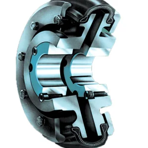
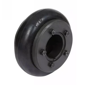
The PIN coupling — formally the bushed pin-type flexible coupling, LT series — is a modified flanged disc coupling that transmits torque through steel pins fitted with rubber or polyurethane bushings. A floating intermediate ring distributes the load evenly across all pin-bushing units, while preserving the compact dimensional envelope of a rigid flange coupling. The PIN coupling is the natural motor coupling selection where a rigid disc has been chewing bearings through alignment-induced loading — direct upgrade in the same machine envelope, no baseplate modification, immediate bearing-life improvement.
PIN Coupling LT Series Specifications
The LT series covers seven sizes from LT1 through LT7, spanning the industrial drive torque envelope from 16 N·m for fractional-kilowatt motor connections up to 2500 N·m for medium-heavy gearbox input drives. Each size is supplied with a full bore range allowing matched-bore (same diameter both ends, typical motor-to-pump) or mismatched-bore (different diameter each end, typical motor-to-gearbox) configurations. The torque rating below is the continuous rating; peak transient torque rating is approximately 2.5× the continuous value.
| Model | Nominal Torque (N·m) | Max Speed (rpm) | Bore Range (mm) | Outer Diameter (mm) | Bushing Material |
|---|---|---|---|---|---|
| LT1 | 16 | 5600 | 12 – 20 | 90 | NBR Rubber |
| LT2 | 40 | 4500 | 18 – 30 | 120 | NBR Rubber |
| LT3 | 100 | 4000 | 22 – 45 | 155 | NBR Rubber |
| LT4 | 250 | 3550 | 30 – 60 | 195 | NBR / Polyurethane |
| LT5 | 500 | 3150 | 38 – 75 | 240 | NBR / Polyurethane |
| LT6 | 1250 | 2800 | 50 – 95 | 300 | NBR / Polyurethane |
| LT7 | 2500 | 2500 | 65 – 110 | 380 | NBR / Polyurethane |
Bushing material selection drives the application envelope. Standard NBR rubber bushings cover general industrial duty up to 80°C ambient with good oil and chemical resistance. Polyurethane bushings — available from LT4 upward — extend the operating temperature to 100°C, exhibit higher fatigue life under high-cycle duty, and tolerate oil contamination significantly better. Specify polyurethane bushings for reversing drives, high-cycle start-stop applications, and elevated-temperature service environments.
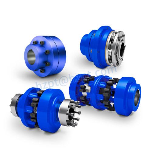
PIN Coupling LT Series – bushed pin-type flexible coupling. Direct rigid-coupling envelope upgrade with moderate misalignment compensation. Ever Power Flange Couplings Australia Ltd.
How the PIN Coupling Transmits Torque
Two flanged hubs face each other across a small axial gap. Each hub carries a circumferential row of pin holes on the rated bolt circle. Steel pins pass through the holes on one hub and project into rubber or polyurethane bushings seated in the opposing holes on the other hub. The intermediate floating ring captures the pins and distributes the load circumferentially — under no load, all pins carry equal share of the rated torque; under misalignment, the floating ring shifts slightly to maintain even load distribution.
Torque transmission occurs through bushing compression as the pins displace circumferentially under load. Angular misalignment compensation comes from the elastic deflection of the bushings in the axial direction; parallel offset compensation comes from radial bushing deflection. Both deflection modes are accommodated within the elastic limit of the bushing compound up to the rated misalignment envelope — typically 0.3° angular and 0.2 mm parallel offset across the LT series. Excursions beyond rated misalignment accelerate bushing fatigue and shorten coupling service life.
Why the Floating Ring Matters
Without the floating intermediate ring, pin-and-bushing couplings suffer from load concentration on whichever pin happens to engage first under torque application. The floating ring forces equal pin engagement around the circumference, distributing the torque transmission load across all pin-bushing units simultaneously. This load equalisation is the engineering feature that distinguishes the LT-series PIN coupling from cheaper pin couplings that omit the floating ring — and the reason the LT coupling delivers the published torque rating reliably across its full service life rather than only at start of life.
Construction and Material Specification
The hub flanges are machined from medium-carbon steel forgings or ductile cast iron depending on size class. Bore tolerance is ISO H7 with standard parallel keyway as published in the dimensional documentation; metric and imperial keyway profiles are available as standard, and larger sizes (LT4 upward) support taper-bushed bore options for higher torque-transmission reliability. Surface treatment is standard industrial phosphate-and-paint or zinc plating for outdoor and marine environments.
Pin elements are turned from alloy steel rod with the bushing engagement surface ground to commercial precision tolerance and case-hardened for wear resistance. Polyurethane bushings are cast from industrial-grade polyurethane elastomer with shore A hardness selected for the size class — softer compounds for small sizes where shock absorption dominates and harder compounds for large sizes where torque transmission dominates. NBR rubber bushings are moulded from nitrile compound with internal reinforcement on the larger sizes.
Engineering Features of the LT PIN Coupling
Flanged disc form factor matches rigid flange coupling dimensions for direct in-envelope replacement. Bolt circle, bore range, and overall length identical to equivalent rigid coupling — no baseplate or shaft modification required for retrofit installation.
Intermediate floating ring forces equal pin engagement around the circumference. Torque transmission distributed evenly across all pin-bushing units. Delivers published torque rating consistently across the full service life rather than only at start of life.
Standard NBR rubber bushings for general industrial duty up to 80°C. Polyurethane bushings (LT4 upward) for elevated temperature to 100°C, oil-contaminated environments, high-cycle reversing duty, and extended fatigue life.
Bushings removable through the floating ring without taking the hubs off the shafts. Routine bushing replacement is a single-shift maintenance task at scheduled outage. Replacement bushing sets stocked separately at our Sydney warehouse.
Lower acquisition cost than tyre, disc, and diaphragm couplings at equivalent torque rating. Simple installation procedure. Minimal lubrication and adjustment requirements. The standard economical selection for general industrial motor-to-gearbox drives.
Angular up to 0.3°; parallel offset up to 0.2 mm. Adequate for typical industrial motor-to-gearbox alignment quality after laser alignment to specification. Larger compensation requires tyre or other elastomeric coupling selection.
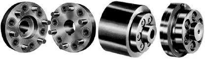
PIN coupling internal construction – steel pin, rubber bushing, floating intermediate ring distributes load across all pin-bushing units evenly.
Application Field for the LT PIN Coupling
General motor-to-gearbox connections across Australian manufacturing plant are the heartland application for the LT PIN coupling. Pump and fan drives where the compact flanged envelope must be retained from an existing rigid coupling installation. Conveyor and machine tool motor connections where the cost-effective flexible coupling solution carries the routine industrial duty without the higher acquisition cost of a tyre or disc coupling. Replacement of rigid flange couplings where alignment-induced bearing wear has been chewing through gearbox input bearings within 12 months.
Industrial Sectors That Specify the LT Series
Water utility pump stations across New South Wales and Queensland specify the LT series for the standard centrifugal pump motor connection — moderate misalignment compensation, low maintenance, long service life with replaceable bushing elements. Food processing plant uses the polyurethane bushing variant where the operating environment includes water washdown and food-grade oils. Bulk material handling plant uses the LT4 through LT7 sizes for conveyor head drive connections where the rigid-disc retrofit upgrade is the typical specification path. Steel and metallurgical plant uses the larger sizes for furnace auxiliary drives and casting machine motor connections.
Selecting the Correct LT PIN Coupling Size
Size selection starts with motor nameplate torque multiplied by an application service factor. Pump and fan drives use a service factor of 1.25 to 1.5 for steady-state operation. Conveyor and material handling drives use 1.5 to 2.0 for normal duty and 2.0 to 2.5 for shock-loaded conveyor restart applications. Reversing duty drives use 2.0 to 3.0. Multiply motor nameplate torque by the appropriate service factor; the resulting design torque must not exceed the LT nominal torque rating.
Bore selection follows the shaft diameters at each end — typically the motor shaft on one end and the pump or gearbox input shaft on the other. Both bore diameters must fall within the published bore range for the selected size; mismatched bore diameters at each end are supported as a standard configuration. Specify both bore diameters and the keyway profile at order entry. For sizes LT4 upward where the application includes torque reversal or shock loading, the taper-bushed bore option provides more reliable torque transmission than the standard parallel-bore keyed connection.
Installation Workflow for the LT PIN Coupling
The PIN coupling installation workflow follows the standard flanged-disc coupling procedure with the addition of correct pin and bushing seating before flange bolting. The five-step workflow below covers initial installation; the same workflow applies in reverse for bushing replacement at scheduled maintenance, except that hub removal from the shafts is not required for bushing-only service.
Mount both flanged hubs on their shafts with the flange faces toward each other across the rated axial gap. Confirm shaft engagement length and parallel key seating. Bring driver and driven equipment to rough alignment with straight edge and feeler gauges before precision laser alignment.
Align angular and parallel offset to within half the rated envelope — typically 0.15° angular and 0.1 mm parallel offset. This leaves headroom for foundation settlement and thermal growth during operating life. Document final alignment values in the equipment maintenance record for future reference.
Insert the steel pins through the pin holes on one hub flange, passing each pin through the floating ring and into the rubber or polyurethane bushing on the opposing hub flange. Confirm each pin is fully seated through the bushing depth. The floating ring captures the pin set as the assembly is brought together.
Tighten the pin retaining hardware progressively in alternating sequence to the specified torque. Torque values are published per size in the documentation pack. Apply locking compound to threads per specification. Verify the floating ring rotates freely between the hub flanges with the pins fully seated.
Bump-start the drive to confirm correct rotation and engagement. Run for 30 minutes at progressive load monitoring noise and coupling temperature. At first scheduled maintenance (typically 1000 hours), inspect bushing condition through the access slot — no replacement required if bushings show no surface cracking or compression set.
Request an LT PIN Coupling Quote
Maintenance and Bushing Replacement
The LT PIN coupling is one of the lowest-maintenance flexible coupling types — no lubrication required, no scheduled adjustments, and bushing replacement only at end of element life. Standard bushing service life is 3 to 5 years in normal industrial duty with correct alignment; reversing duty and high-cycle applications may see bushing replacement every 1 to 2 years. The replacement procedure does not require hub removal from the shafts — bushings are accessed through the floating ring with the hubs in service position.
Bushing wear indicators include: increasing backlash between drive and driven shafts measured at the hub OD (replace at 2° or above); audible knock from the coupling at torque reversal (replace immediately if intermittent, urgently if continuous); visible surface cracking or compression set on the bushings during routine inspection; vibration signature change at constant load conditions. Address any wear indicator promptly to avoid pin damage that would require pin replacement in addition to bushing replacement.
Why Choose Ever Power Australia
Ever Power Flange Couplings Australia Ltd. carries the LT PIN coupling range in Sydney warehouse stock — LT1 through LT7 with both NBR rubber and polyurethane bushing options available for same-day or 1-to-3 working day dispatch. Replacement bushing sets, pins, and floating rings are stocked separately for field service across New South Wales mining, water utility, food processing, and general manufacturing installations. The ISO 9001 quality management system ensures consistent hub dimensions, pin hardness, bushing compound, and floating-ring fit across the entire LT range.
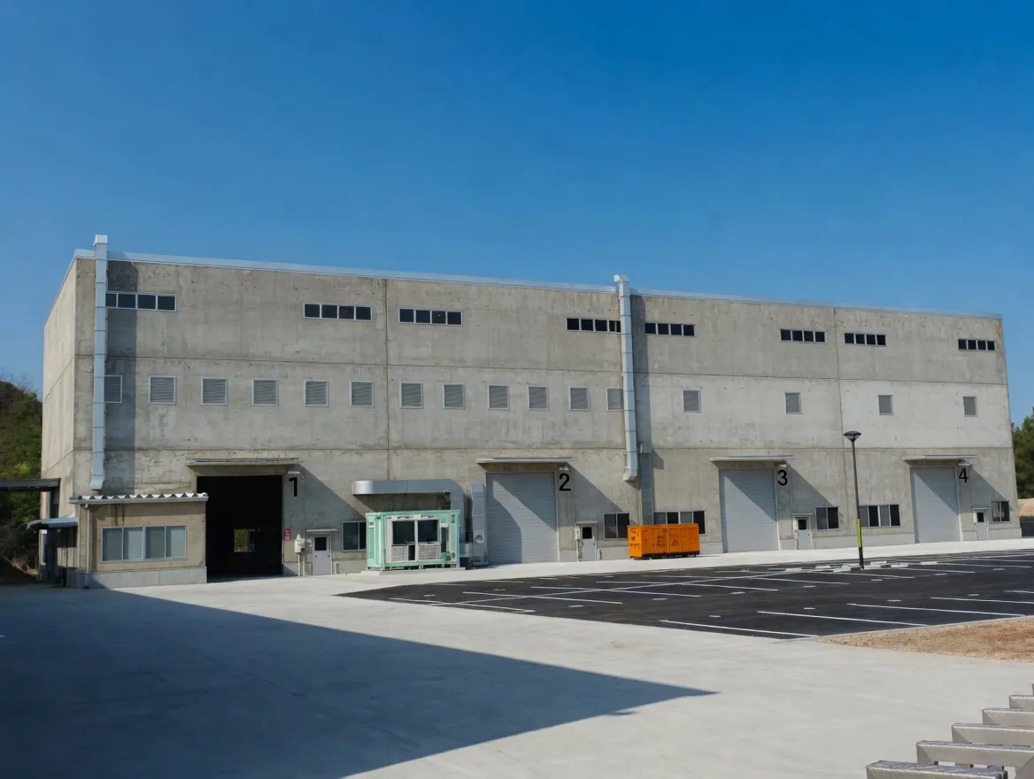
Ever Power manufacturing facility — ISO 9001 certified, 12,000 m², 108 dedicated coupling machines, 20+ years of production experience.
Every order placed with our Sydney team is backed by full material traceability, dimensional inspection certificates on request, and direct access to the engineers who specified, machined, and packed your coupling. We do not subcontract technical support — when you phone +61 2 9708 3322 during NSW business hours, you reach the people who actually know the product.
Frequently Asked Questions
Quick answers from our Sydney technical team. Contact us for application-specific guidance.
1. How does the LT PIN coupling compare to a tyre coupling for the same drive? +
2. When should I specify polyurethane bushings instead of NBR rubber? +
3. Can the LT PIN coupling be installed in place of an existing rigid flange coupling? +
4. How long do the bushings last in normal industrial service? +
5. Are different bore diameters at each end supported as standard? +
Request a Quote — Sydney NSW Stock
Tell us your motor power, shaft diameter, and operating environment. Our New South Wales coupling team confirms availability and pricing within one business day, with same-day dispatch on standard sizes from Condell Park.
Ever Power Flange Couplings Australia Ltd. · 27 Harley Crescent, Condell Park NSW 2200 · [email protected]