
Motor overload protection is a system-level engineering requirement — it involves the motor’s electrical protection system, the driven machine’s mechanical design, and the coupling between them working together to prevent motor burnout, gearbox damage, and driven machine failure under abnormal load conditions. The coupling’s role in this system varies considerably depending on its design: a standard flexible coupling provides no intentional overload protection; a YOX series fluid coupling provides inherent, hydrodynamic overload protection at a torque level determined by the coupling’s fill and slip characteristics; and a snake spring coupling provides shock absorption that limits peak torques during transient overload events. Understanding these differences is fundamental to selecting the right coupling when overload protection is a specific engineering requirement.
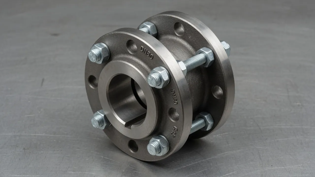
Motor Overload: What It Is and Why Couplings Are Part of the Solution
An electric motor can be overloaded in two distinct ways, each requiring a different protective response:
Electrical overload — the motor draws more current than its rated value because the driven load demands more torque than the motor’s nominal rating. The motor windings overheat if the excess current is sustained. Protection is provided by the motor’s electrical protection: thermal overload relay, motor protection relay, or electronic soft-starter with current limiting. This protection is independent of the coupling.
Mechanical overload — a transient or sustained mechanical event imposes a torque on the motor shaft that exceeds its rated output. This can arise from a driven machine jam (torque spikes to many times rated), a sudden load increase, or a DOL start against a fully loaded drive. The mechanical overload can damage the motor’s rotor bearings, the coupling, the gearbox, or the driven machine before the electrical protection operates. The coupling is the mechanical device in this protection chain.
How Different Coupling Types Handle Overload
| Coupling Type | Overload Mechanism | Protection Type | Torque Limit | Reset Method |
|---|---|---|---|---|
| Standard flexible tyre (F-type) | Element compression fatigue and eventual failure | Uncontrolled — failure mode only | Element’s ultimate capacity (typically 2–3× rated) | Replace elastomeric element |
| Snake spring coupling (EP-JSA) | Progressive spring stiffening absorbs peak torque | Shock absorption — reduces peak transmitted torque | Peak absorbed by spring element — not a hard limit | Automatic — spring element rebounds |
| Fluid coupling (YOX series) | Hydrodynamic slip limits transmitted torque during stall | Inherent — limits torque at any overload | 1.3–1.8× rated torque during stall | Automatic — resumes when load reduces; fusible plug if sustained |
| Torque limiter coupling | Calibrated clutch slips at set torque | Calibrated — precise torque limit | Set torque (calibrated) | Manual reset or automatic re-engage on load reduction |
| Shear pin coupling | Pins shear cleanly at design torque | Sacrificial — drive disconnected | Set torque (calibrated pin cross-section) | Replace sheared pins |
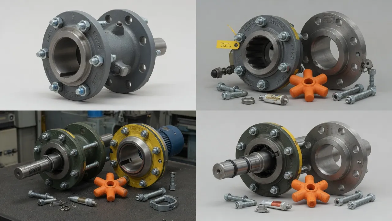
Fluid Coupling Overload Protection — The Engineering Detail
The YOX series fluid coupling provides overload protection through a fundamental property of hydrodynamic power transmission: the torque transmitted through the oil film is limited by the slip between the impeller and turbine and is independent of the motor’s ability to produce higher torque. When the driven load is greater than the coupling’s stall torque (typically 1.3–1.8× rated), the turbine remains stationary and the impeller slips against the oil at maximum slip. The motor sees a load of 1.3–1.8× rated torque — which it can sustain thermally for a limited period — rather than the potentially unlimited torque of a direct-on-line jam.
The fusible plug is the secondary protection mechanism. If the stall condition is sustained beyond the coupling’s thermal capacity, the oil temperature rises to the fusible plug’s melting point (120°C), the plug melts, and the oil discharges from the coupling — mechanically disconnecting the drive. The fusible plug replacement is the maintenance action required after this event, not a motor or gearbox repair.
Snake Spring Coupling Shock Absorption — How It Limits Peak Torque
The EP-JSA snake spring coupling does not impose a hard torque limit — it absorbs energy from a transient torque peak through the elastic deformation of the steel spring element. As the torque peak arrives, the spring bends more deeply into the hub tooth slots, increasing torsional compliance and extending the peak torque duration without amplifying it. The energy stored in the spring is released gradually after the peak passes, spreading the impulse over a longer time period and reducing the peak torque transmitted to the motor and gearbox.
This shock absorption mechanism is particularly effective for crusher and conveyor applications where material impact events produce sharp torque spikes of very short duration (milliseconds). The spring element absorbs these spikes before they reach the motor, protecting motor bearings from the impact loads that rigid couplings would transmit unchanged.
Frequently Asked Questions
Need Expert Coupling Advice?
Our engineering team in Condell Park NSW is ready to help — free of charge.