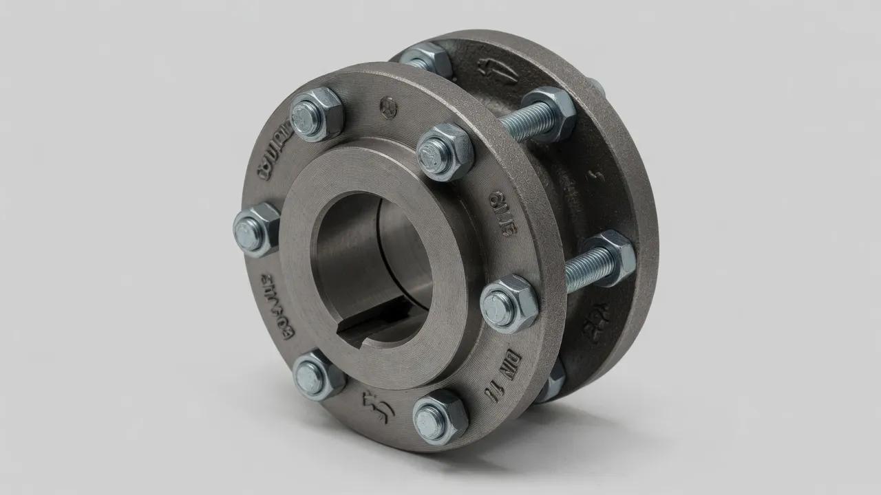
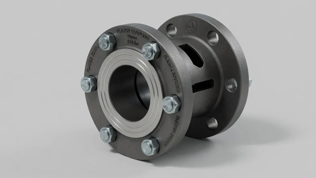
A coupling hub crack is the most serious single damage finding in a coupling inspection — and the one that requires the most unambiguous response. Unlike a worn elastomeric element (which degrades predictably and provides warning time) or a loose bolt (which can be corrected in place), a cracked hub must come out of service immediately. The engineering reason is straightforward: a crack in a rotating load-bearing component under cyclic torque loading will propagate. The question is not whether the hub will fracture, but when — and at what operating speed. This guide explains why coupling hub cracks occur, how to recognise them, and how to prevent them through correct specification and installation — covering both cast iron and steel rigid coupling hubs and the heavy-duty shaft coupling range used in high-torque industrial applications.
The Five Root Causes of Coupling Hub Cracking
1 — Keyway Stress Concentration (Most Common)
The keyway creates a stress concentration at its root corners. Under cyclic torque, the stress at the keyway root can be 2–3× the nominal bore stress, and over millions of load cycles, this concentrated stress exceeds the material’s fatigue limit and initiates a crack. The crack propagates perpendicular to the maximum principal stress direction — typically radially outward from the keyway root corners toward the hub OD. Sharp keyway root corners (machined without the specified radius) dramatically increase the stress concentration factor and accelerate crack initiation.
2 — Shock Overload (Single Event)
A single torque event exceeding the hub material’s ultimate tensile strength or fracture toughness produces an immediate crack or fracture — not the progressive fatigue mechanism of the keyway root crack. Shock overloads occur from pump or compressor jams, crusher blockages, motor stall starts, and coupling misalignment-induced impact loading. The diagnostic distinction: a fatigue crack typically starts at a stress concentration and propagates gradually; a shock fracture typically extends across a large cross-section in a single event.
3 — Installation Damage from Incorrect Hub Fitting
Using a steel hammer to drive a hub onto a shaft applies localised impact loads to the hub bore that can initiate micro-cracks, particularly at the hub bore edge. These cracks are invisible at installation but propagate under running loads, producing hub fracture weeks or months later with no obvious operational cause. The correct procedure — oven heating for interference fits, soft-faced mallet with brass drift for clearance fits — eliminates this damage mechanism.
4 — Material Under-Specification for the Application
A grey cast iron hub (GG25) under repeated shock loading will eventually crack — not because the hub was incorrectly sized by the torque calculation, but because the material is inherently brittle under impact. For any application with shock loads (crushers, reciprocating compressors, bucket elevators, frequent DOL starting of high-inertia loads), ductile iron (SG500) or carbon steel (C45) hubs are the correct material choice. The substitution of grey cast iron for ductile iron is often driven by purchase price, but the repeated replacement cost from cracking always exceeds the initial cost saving.
5 — Fretting-Induced Hub Bore Fatigue
Micro-slip at the bore-to-shaft interface under cyclic torque generates fretting damage at the hub bore surface. The fretting produces a rough, oxidised surface layer with embedded micro-cracks that serve as fatigue initiation sites. As the hub continues in service, these fretting cracks propagate inward under the cyclic hoop stress from the bore preload, eventually producing a longitudinal crack along the hub bore length. Fretting-induced cracking is most common on hubs with loose bore-to-shaft fits in high-torque or reversing applications.
Preventing Hub Cracking — Material and Design Choices
Application
Risk Level
Correct Hub Material
Keyway Specification
Smooth centrifugal pump, DOL
Low
GG25 cast iron acceptable
ISO 773 keyway, r ≥ 0.25 mm at root corners
Centrifugal pump, frequent start-stop
Low–Medium
GG25 or SG500 ductile iron
ISO 773, full root radius
Reciprocating compressor or pump
Medium–High
SG500 ductile iron or C45 steel
Full root radius; consider interference fit bore
Jaw crusher, impact crusher
High
C45 steel minimum; 42CrMo4 alloy steel preferred
Full root radius; shrink disc or interference fit
Ball mill or SAG mill
Very High
42CrMo4 alloy steel
Shrink disc — avoid keyway entirely
DOL start, high inertia fan
Medium
SG500 ductile iron or C45 steel
Full root radius; check service factor
Inspection Protocol for Hub Crack Detection
1
Visual Inspection Under Good LightingWith the hub removed from service, clean all surfaces thoroughly. Inspect keyway root corners and hub root radius under bright light with a magnifying glass. Any dark line running perpendicular to the keyway length or radially from the bore surface is a crack until proven otherwise.
2
Dye Penetrant Test for Surface CracksApply dye penetrant to all suspected areas per ASTM E165. After the penetration dwell time, remove excess penetrant and apply developer. Cracks appear as red or fluorescent indications against the white developer background. Dye penetrant is sensitive to surface cracks of 10–15 µm width — far below the visual threshold.
3
Magnetic Particle Inspection (Steel and Ductile Iron Hubs)For ferromagnetic hubs (steel, ductile iron), magnetic particle inspection is more sensitive than dye penetrant and detects both surface and near-surface cracks. Apply wet fluorescent particle suspension and inspect under UV light. Not applicable to aluminium or grey cast iron (non-ferromagnetic).
Frequently Asked Questions
Is a hairline crack in a coupling hub safe to continue operating?+
No. A hairline crack in a coupling hub is not safe to operate through, regardless of how small it appears. Coupling hubs rotate at operating speed carrying full torque — any crack is a fatigue crack initiation site that will propagate under the cyclic loading. The time to complete fracture depends on the crack size, location, material, and loading magnitude, but it cannot be reliably predicted from visual inspection alone. A coupling hub with any visible crack must be removed from service immediately and replaced before any further operation.
What does a coupling hub crack look like?+
Coupling hub cracks most commonly appear at the keyway root corners — the sharp-radius transition between the keyway floor and the keyway walls where stress concentration is highest. They initially appear as fine, dark lines in the surface, often with slight surface discolouration from oxidation of the crack faces. On cast iron hubs, cracks may also appear at the transition between the hub flange and the hub barrel (the root radius). Dye penetrant or magnetic particle inspection reveals hairline cracks that are not visible to the naked eye and should be performed whenever a crack is suspected.
Can a cracked hub be welded and returned to service?+
Welding a cracked coupling hub and returning it to service is not acceptable engineering practice. The weld introduces residual thermal stresses, heat-affected zone embrittlement in the surrounding material, and geometry changes at the weld zone that make the hub structurally inferior to a new hub at the same location. Grey cast iron hubs cannot be reliably welded at all — the material has very limited ductility and is susceptible to cracking in the heat-affected zone. Steel hubs can be welded by a qualified fabricator, but the repaired hub should never be used in a coupling application where the safety of others depends on its integrity.
Why do cast iron coupling hubs crack more often than steel hubs?+
Grey cast iron (GG25) is a brittle material with a tensile strength of approximately 250 MPa and virtually no ductility — it cannot yield plastically before fracture. Under impact loading or cyclic stress above the fatigue limit, grey cast iron cracks rather than deforming. Carbon steel (C45) is ductile — it has a tensile strength above 700 MPa and can sustain significant plastic deformation before fracture. A shock load that fractures a grey cast iron hub will produce visible deformation (yielding) in an equivalent steel hub without fracture. For shock-loaded or impact-prone applications, ductile iron (SG500) or carbon steel hubs are the correct material specification.
Does coupling hub cracking mean the coupling was the wrong size?+
Not necessarily. Hub cracking can result from under-specification (the hub was too small for the applied torque), overload events (a single shock load exceeding the hub’s fracture limit), installation damage (hub cracking from a steel hammer used to drive the hub onto the shaft), or stress concentration from an incorrectly machined keyway (sharp corners at the keyway root instead of the specified radius). Determining which cause applies is important for correct specification of the replacement — a new hub of the same size may crack again if the root cause was overload rather than under-specification.
Need Expert Coupling Advice?
Our engineering team in Condell Park NSW is ready to help — free of charge.