
Gearbox connections present coupling selection challenges from both sides: the input coupling must accommodate the motor speed and protect the gearbox input bearings from motor vibration; the output coupling must handle the much higher output torque and protect the gearbox output bearings from shock loads generated by the driven machine. Getting both right ¡ª with appropriate service factors, correct coupling types for the speed and torque on each side, and material specifications suited to the operating environment ¡ª is the foundation of reliable gearbox performance. The heavy-duty shaft coupling and the EP-JSA snake spring coupling address different positions in the gearbox coupling selection matrix, with the snake spring particularly well suited to the output-side shock absorption role.
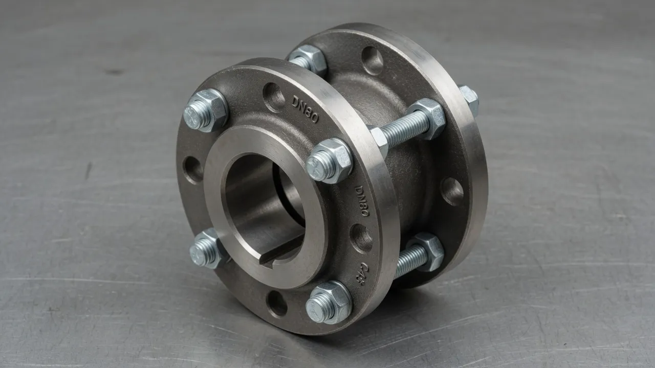
Understanding the Torque Profile Across a Gearbox
A gearbox changes the relationship between torque and speed. If the gear ratio is 10:1 (input speed 1,450 RPM, output speed 145 RPM), the output torque is approximately 10 times the input torque (less the gearbox losses, typically 2¨C3% per gear stage). This fundamental relationship has direct implications for coupling selection on both sides:
Motor shaft torque: 9,550 ¡Á 75 ¡Â 1,450 = 494 Nm ¡ú input coupling specification
Gearbox output torque: 494 ¡Á 10 ¡Á 0.97 = 4,792 Nm ¡ú output coupling specification
The output coupling must handle nearly 10¡Á the torque of the input coupling.
Input-Side Coupling Selection (Motor to Gearbox)
Flexible Tyre Coupling (Standard)
The most common motor-to-gearbox input coupling for industrial drives up to 200 kW. Provides vibration damping and misalignment accommodation. Service factor 1.5¨C2.0 for most applications. Specify 92A PU spider as standard.
Fluid Coupling (High Inertia Loads)
For conveyor, fan, and mill drives where the motor must start a high-inertia gearbox-load combination, a fluid coupling between motor and gearbox provides controlled soft start that protects the gearbox input gears from starting shock. Eliminates the need for star-delta or soft-starter electrical equipment.
Heavy-Duty Flange Coupling (High Power)
For motor-gearbox connections above 200 kW where the motor is DOL-started and the starting torque peak must be handled by the coupling with appropriate margin. Ductile iron or steel hubs; service factor 2.0¨C2.5.
Disc Coupling (Precision Gearboxes)
For precision speed-ratio applications where backlash-free coupling at the gearbox input is required for accurate position or speed control. Zero backlash, high torsional stiffness, maintenance free.
Output-Side Coupling Selection (Gearbox to Driven Machine)
| Driven Machine | Output Torque Range | Load Character | Recommended Coupling | Service Factor |
|---|---|---|---|---|
| Centrifugal pump | 500¨C15,000 Nm | Smooth, continuous | Heavy-duty flexible flange or rigid flange | 1.75¨C2.25 |
| Belt conveyor head shaft | 2,000¨C50,000 Nm | Moderate shock, high inertia | Heavy-duty flange + snake spring for shock | 2.50¨C3.00 |
| Jaw crusher | 5,000¨C100,000+ Nm | Very heavy shock | Heavy-duty rigid flange (output) + fluid coupling (input) | 3.00¨C4.00 |
| Screw conveyor | 500¨C8,000 Nm | Moderate shock | Heavy flange or snake spring coupling | 2.00¨C2.50 |
| Agitator / mixer | 500¨C20,000 Nm | Variable, moderate shock | Heavy-duty flexible flange | 2.00¨C2.50 |
| Ball mill / SAG mill | 50,000¨C500,000+ Nm | Extreme shock, high inertia | Custom heavy-duty coupling ¡ª torsional analysis required | 3.50¨C4.50 |
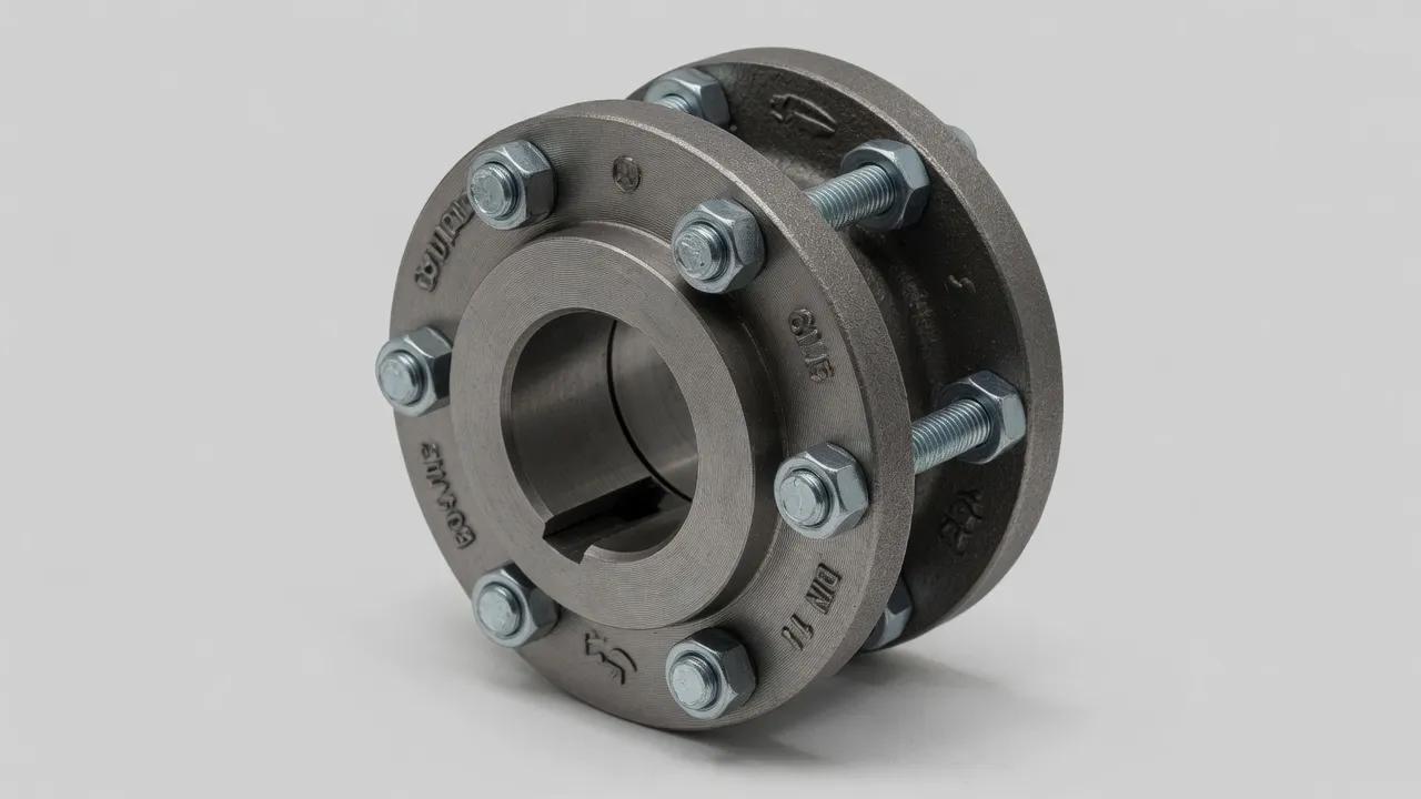
Coupling Backlash and Gearbox Health
A gearbox that is in poor condition ¡ª with worn gear teeth producing excessive backlash ¡ª places additional demands on the connected couplings. When a worn gearbox engages after a direction reversal or a load transient, the gear teeth impact rather than mesh smoothly, producing a torque spike that propagates to both the input and output couplings simultaneously. Flexible couplings on both sides absorb this impact through elastomeric element deformation; rigid couplings transmit it directly to the motor and driven-machine bearings. If gearbox backlash is known to be excessive, upgrading the couplings on both sides to a flexible type ¡ª if they are currently rigid ¡ª provides interim protection while the gearbox is scheduled for repair.
Frequently Asked Questions
Need Expert Coupling Advice?
Our engineering team in Condell Park NSW is ready to help ¡ª free of charge.