
Conveyor systems are among the most demanding coupling applications in Australian heavy industry. A typical belt conveyor in a mining or quarrying operation starts under full load multiple times per shift, transmits sustained high torque for hours at a time, operates in dusty and sometimes wet environments, and is expected to run reliably for months between planned maintenance shutdowns. The coupling is a small component in this system — but its selection has an outsized influence on drivetrain reliability and maintenance cost. This guide covers the coupling selection logic for conveyor applications, with guidance on when to specify a snake spring coupling and when a heavy-duty shaft coupling is the right answer.
The Unique Demands of Conveyor Coupling Applications
What makes conveyor coupling selection different from pump or fan applications is the combination of high inertia, shock loading, and long duty cycles. A belt conveyor head shaft experiences: starting torque from 1.5–3× running torque at each start; impact loads when large material lumps engage the belt; sustained running torque at 80–100% of rated capacity; and occasional stall loads when the belt jams — all in the same operating session. The coupling must handle all of these loading modes without failure or excessive wear.
Unlike a pump coupling where the load is relatively smooth and continuous, a conveyor coupling operates in a regime where the ratio of peak torque to average torque can be 3:1 or higher. This peak-to-average ratio is the primary sizing driver — and it is why conveyor coupling service factors are typically 2.0–3.5, significantly higher than the 1.5 factor used for smooth centrifugal pump drives.
Conveyor Drive Configuration — Where Couplings Sit in the System
Motor to Fluid Coupling
First coupling in the drive train. A fluid coupling between the motor output shaft and the gearbox input limits starting torque, provides soft start, and protects the gearbox from locked-rotor overload. Most common on conveyors above 30 kW in Australian mining.
Gearbox Input Coupling
If no fluid coupling is fitted, a flexible jaw or pin coupling connects the motor directly to the gearbox input shaft. Must handle the full DOL starting torque — a significantly higher service factor applies than for a fluid-coupling-driven gearbox.
Gearbox Output to Head Shaft
The highest-torque coupling in the system — after gear reduction, the output torque can be 10–50× the motor torque. This coupling is invariably a heavy-duty flange or grid coupling rated for the conveyor’s full running torque with a 2.5–3.0 service factor.
Take-Up Drum Drive
Take-up drums on long conveyors are sometimes driven by a separate motor, which requires its own coupling. A flexible flange coupling with a tyre element is typical here — the take-up tension load varies with belt loading and a flexible coupling protects the take-up motor bearings from the resulting load swings.
When to Specify a Snake Spring Coupling on a Conveyor
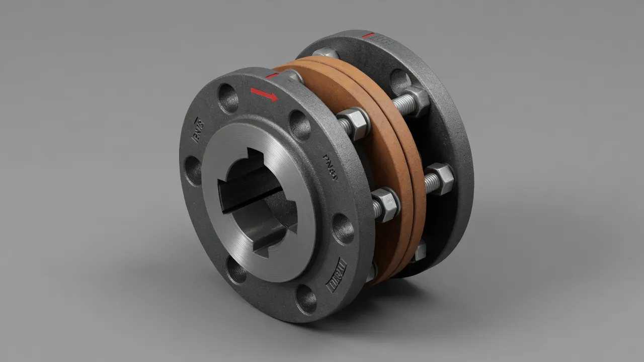
The EP-JSA snake spring coupling is particularly well suited to the gearbox-to-head-shaft position on medium-sized conveyors. The sinusoidal spring element provides torsional shock absorption during belt starts and material impact events, and the spring can be replaced as a single component without disturbing either hub. Key advantages over jaw or tyre couplings in this position are the spring element’s ability to handle higher peak torques at equivalent bore sizes and its resistance to contamination — the spring element is less sensitive to dust and moderate moisture ingress than elastomeric spider or tyre elements.
Coupling Service Factors for Conveyor Applications
| Conveyor Type | Load Character | Service Factor | Coupling Recommendation |
|---|---|---|---|
| Short belt conveyor (<50m) | Moderate start, smooth running | 1.75–2.0 | Flexible pin coupling or jaw coupling |
| Long belt conveyor (>50m) | High inertia, shock loads | 2.5–3.0 | Fluid coupling + heavy flange at head shaft |
| Bucket elevator | High peak torque at bucket engagement | 2.5–3.0 | Snake spring or heavy flange coupling |
| Screw conveyor | Shock loads from material build-up | 2.0–2.5 | Jaw coupling or flexible pin coupling |
| Apron feeder / plate conveyor | Very high torque, shock loading | 3.0–4.0 | Heavy-duty flange coupling, steel hub |
| Pipe conveyor | High tension, smooth running | 2.0–2.5 | Flexible tyre or flange coupling |
Alignment Requirements on Conveyor Drives
Conveyor head shaft alignment is frequently neglected compared to pump or compressor applications — partly because the coupling is hidden inside a guard and partly because misalignment develops slowly as the conveyor structure settles after construction. Annual laser alignment checks on all conveyor drive couplings are strongly recommended. Misalignment on a conveyor drive produces exactly the same bearing damage as on any other coupled machine — and the consequences of a head pulley bearing failure on a long belt conveyor are typically a multi-day unplanned shutdown.
Frequently Asked Questions
Need Expert Coupling Advice?
Our engineering team in Condell Park NSW is ready to help — free of charge.