Description
The flexible beam coupling — also known as a helical coupling or single-body spiral coupling — is machined from a single piece of aluminium alloy or stainless steel bar, with one or more helical cuts spiralling through the body to create flexible sections that bend under misalignment while transmitting torque through the remaining solid metal. The split-clamp bore retention grips each shaft with a friction fit and zero keyway. This single-component design produces the smallest envelope and highest torsional bandwidth of any flexible coupling type — the engineering default for servo motor, encoder, stepper, and laboratory instrumentation drives.
Flexible Beam Coupling Specifications
The beam coupling range covers bore diameters from 3 mm to 40 mm and continuous torque ratings from 0.05 N·m on the smallest instrument couplings up to 30 N·m on the larger servo-motor sizes. The same coupling body geometry serves a wide range of bore combinations — different bore at each end of the coupling is the standard configuration, not a custom variant. Operating speed is rated up to 10,000 rpm for standard sizes, with precision-balanced variants extending to 25,000 rpm for spindle drives.
| Outside Diameter (mm) | Length (mm) | Bore Range (mm) | Max Torque (N·m) | Max Speed (rpm) | Material |
|---|---|---|---|---|---|
| 12 | 16 | 3 – 6 | 0.1 | 20000 | 6061 Aluminium |
| 19 | 25 | 4 – 10 | 0.5 | 15000 | 6061 Aluminium |
| 25 | 35 | 6 – 12 | 1.5 | 12000 | 6061 Aluminium |
| 32 | 45 | 8 – 16 | 3.5 | 10000 | 6061 Aluminium |
| 40 | 55 | 10 – 20 | 7.0 | 8000 | 6061 Aluminium |
| 50 | 65 | 12 – 24 | 12 | 7000 | 6061 Aluminium |
| 56 | 75 | 14 – 28 | 20 | 6000 | 6061 Aluminium |
| 66 | 90 | 16 – 35 | 30 | 5000 | 6061 Aluminium |
| 80 | 105 | 20 – 40 | 45 | 4000 | 6061 Aluminium / Stainless |
Stainless steel body construction is available for cleanroom, food-processing, and corrosive environment installations across the full size range. The stainless variant exhibits slightly higher torsional stiffness than the aluminium variant of the same size — useful where servo bandwidth is more important than peak shock absorption. Both materials use the same split-clamp bore retention; both materials support different bores at each end as standard.
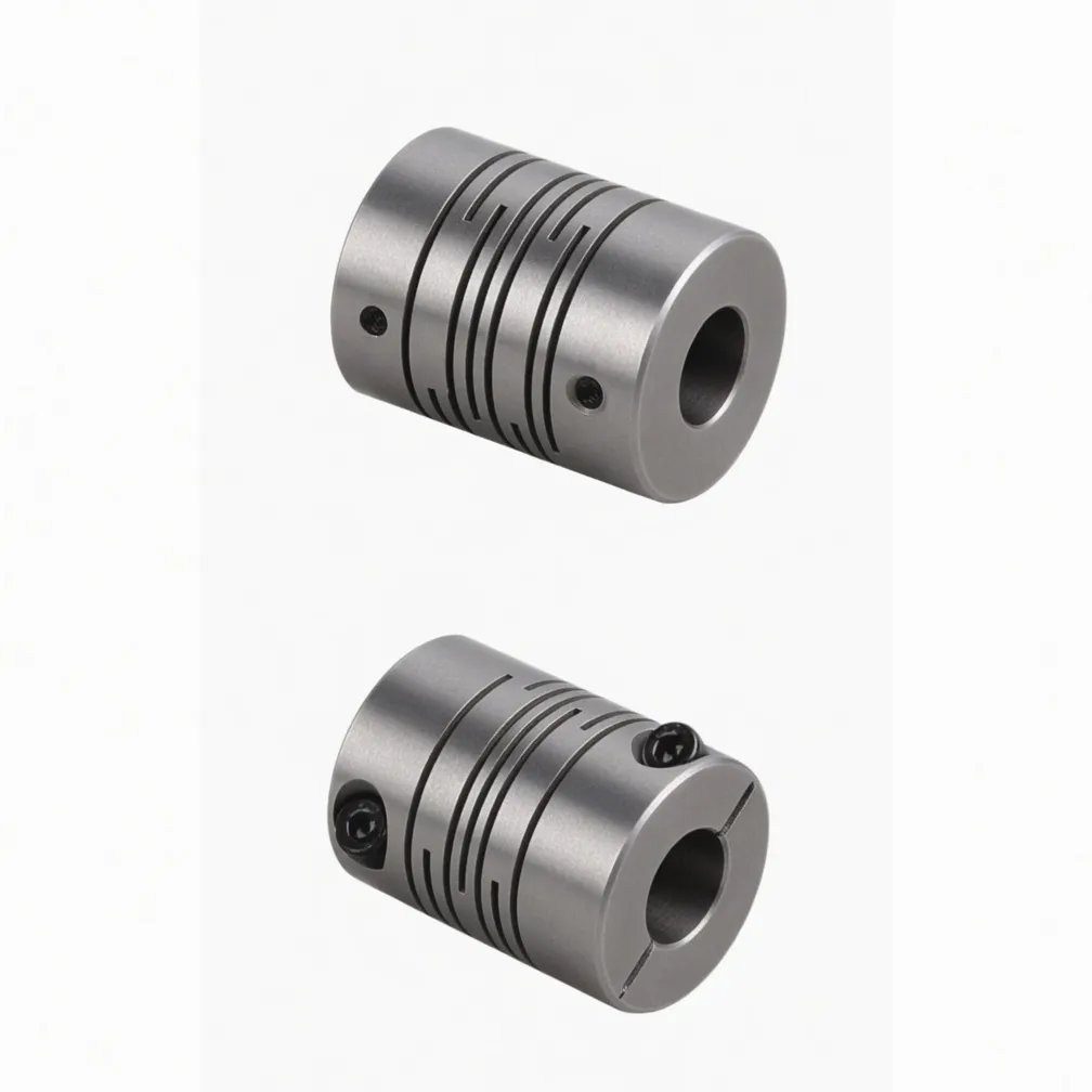
Flexible Beam Coupling – single-body aluminium alloy with helical cut. Split-clamp bore retention, zero backlash. Ever Power Flange Couplings Australia Ltd.
How the Flexible Beam Coupling Transmits Torque
A single piece of aluminium bar is turned to the rated outside diameter and the required overall length. One or more helical cuts are machined through the bar wall — typically a single-start spiral for the smallest sizes through three-start spirals for the largest. The cuts produce flexible beam sections that connect the two bore ends through a series of helical strips. Torque is transmitted through these strips by torsion; misalignment is accommodated by bending of the same strips.
Because the entire coupling is one piece of metal with no separate flexible element, no fasteners, and no joints, the torque-transmission stiffness is precisely defined by the geometry of the helical cut. The torsional stiffness is high enough to deliver clean servo bandwidth without resonance issues, yet low enough to absorb the small shock loads typical of servo positioning duty cycles. The split-clamp bore retention then connects each end to its shaft with no keyway and no set-screw flat — pure friction grip, with no backlash under torque reversal.
Why Zero Backlash Matters for Servo Drives
Servo-driven positioning systems rely on the coupling preserving the angular position signal from motor encoder to driven shaft. Any backlash in the coupling becomes lost motion in the position loop — overshoot on direction reversals, hunting at the final commanded position, and degraded settling time. A keyed coupling has clearance between key and keyway; a set-screw coupling allows the screw to dent the shaft and create lost motion; a flexible spider coupling has elastomer compression that takes up under torque reversal. The split-clamp beam coupling is the only commonly available motor coupling design that has true zero backlash under bidirectional torque.
Construction and Material Specification
The standard body material is 6061-T6 aluminium alloy — chosen for the combination of moderate elastic modulus (delivers flexibility at small section sizes), high yield strength (allows operation near the elastic limit of the helical cut), low density (minimises rotational inertia for high servo bandwidth), and ease of high-precision machining. The helical cuts are produced on multi-axis CNC mills with positional accuracy to within 0.02 mm of nominal, maintaining the torsional and bending stiffness consistency required by precision motion control.
Stainless steel construction uses AISI 304 or 316L alloy depending on the environment specification. The stainless body matches the aluminium body dimensionally but exhibits higher torsional stiffness, lower thermal expansion, and inherent corrosion resistance for food processing, cleanroom, marine, and chemical environment installations. The split-clamp screws are stainless or alloy steel with anti-corrosion treatment; tapered split-clamp variants are available for installations where standard cylindrical clamp engagement is impractical.
Engineering Features of the Beam Coupling
Split-clamp friction grip on the shaft — no key, no keyway, no set-screw flat. Zero clearance under torque, zero clearance under torque reversal. Critical for servo positioning systems and high-precision instrumentation.
Single-piece aluminium body has the lowest mass and inertia of any flexible coupling type at equivalent torque rating. Minimises servo response time and improves position-loop bandwidth in motion control systems.
Single-component construction produces the smallest outside diameter and shortest overall length of any flexible coupling type. Fits the tight motor-encoder space envelope in CNC machine tools and laboratory instrumentation.
Servo motor shaft on one end and encoder shaft, ballscrew shaft, or driven shaft on the other end — different sizes are the standard configuration, not a custom modification. Specify both bore diameters at order entry.
Stainless variant available across the full size range for food processing, cleanroom, marine, and corrosive environment installations. Same dimensions, same split-clamp retention, higher torsional stiffness.
No lubrication required. No periodic adjustment. No wearing parts. Standard service life is the operating life of the equipment in normal motion control duty cycle.
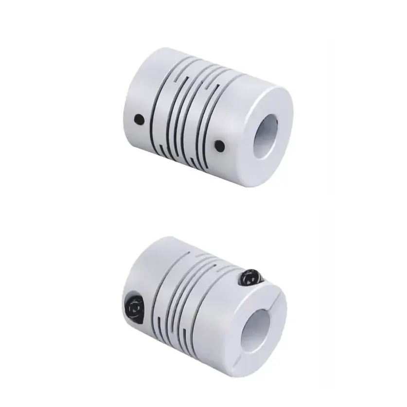
Flexible beam coupling – helical cut detail. Single-piece construction supports different bores at each end as standard. Bore range 3 to 40 mm.
Application Field for the Beam Coupling
Motion control systems are the natural application field for the flexible beam coupling. Servo motor to encoder connections in CNC machine tools, robotic arm joint drives, semiconductor wafer-handling stages, automated laboratory instruments. Stepper motor to ballscrew connections on linear positioning stages, 3D printer kinematics, optical positioning systems, automated microscopy. Any application where the coupling must combine zero backlash, low inertia, and compact envelope leads to the beam coupling as the engineering selection.
Medical, Aerospace, and Cleanroom Applications
Medical device manufacturers use the stainless steel beam coupling in pharmaceutical filling machines, infusion pumps, laboratory blood analysers, and automated assay equipment — applications where contamination from elastomeric coupling outgassing or grease purge from a lubricated coupling would compromise the process. Aerospace test rigs use the beam coupling in attitude-control reaction wheel test stands, gyroscope test fixtures, and propulsion test instrumentation. Cleanroom equipment manufacturers specify the stainless variant for wafer handlers and substrate transport mechanisms where any contamination event halts a production line.
Selecting the Correct Beam Coupling Size
Size selection starts with the rated continuous torque from the motor specification multiplied by an application service factor — typically 1.5 to 2.0 for servo positioning duty cycles, 2.0 to 3.0 for stepper motor applications with frequent start-stop. The resulting design torque is matched against the published nominal torque to select the smallest beam coupling that meets the requirement. Avoid oversizing; the lower inertia of the smaller coupling improves servo performance.
Bore diameters at each end are then specified independently to match the motor shaft and the driven shaft. Both bores must fall within the published bore range for the selected outside-diameter size — typically a 4:1 range from minimum to maximum. The split-clamp bore design tolerates the full published range without any change in performance characteristic. Specify the bore tolerance for each shaft (typically h7 for motor shafts, h6 for ground precision shafts) at order entry so the clamp screw torque can be verified against the bore fit.
Installation Workflow for the Beam Coupling
Beam coupling installation is the simplest of any flexible coupling type because there are no separate fasteners, no spider element to fit, and no lubrication. The four-step workflow below covers initial installation; the same workflow applies in reverse for coupling removal if it ever becomes necessary. Most beam couplings remain installed for the operating life of the equipment.
Inspect the coupling for shipping damage. Verify the bore diameters at each end against the shaft diameters — they should be a slip fit with no observable interference. Verify the split-clamp screws are present and the clamp slots are clean.
Slide the coupling onto the motor shaft until the motor-shaft bore is fully engaged. Position the driven equipment (encoder, ballscrew, sensor) into the other bore until both bores are fully engaged with their respective shafts. Confirm the helical cut is centred axially between the two shafts.
Tighten the split-clamp screws progressively in alternating sequence to the specified torque. Standard torque values are published per size; typically 1 to 5 N·m for small sizes and 5 to 15 N·m for larger sizes. The clamp slots close partially as the screws come up to torque — this confirms the friction grip is established.
Rotate the shaft by hand and observe the coupling response. Smooth rotation with no axial wobble confirms correct installation. Run the motor at progressive speed monitoring vibration; correct installation produces no observable vibration signature from the coupling at any operating speed.
OEM Cross-Reference for Beam Couplings
Direct dimensional cross-reference is supplied for Ruland beam couplings, Huco beam couplings, Helical beam couplings, Lovejoy ROSTA beam couplings, and Misumi beam coupling product lines. Provide the OEM part number — typically a five to seven character alphanumeric code — and our Sydney engineering team confirms the equivalent EP beam coupling size with documented dimensional comparison within one business day. Standard cross-reference orders ship within 1 to 3 working days for stocked sizes.
Custom beam coupling configurations are available for specialised applications including high-vacuum service (custom outgassing-controlled materials), magnetic-resonance imaging compatible service (titanium and special non-magnetic alloy bodies), and cryogenic temperature service (special stainless and Invar variants). Provide the application environment specification at quotation stage — custom material lead times are typically 4 to 6 weeks from order confirmation.
Why Choose Ever Power Australia
Ever Power Flange Couplings Australia Ltd. carries the standard EP beam coupling range in Sydney warehouse stock for same-day dispatch on commonly specified servo and stepper motor sizes. Both aluminium and stainless body variants are stocked from 12 mm through 50 mm outside diameter. Different bores at each end is a standard no-charge configuration; custom material variants for cleanroom, medical, and aerospace applications are supplied from our in-house engineering capability with full material traceability and specification documentation.

Ever Power manufacturing facility — ISO 9001 certified, 12,000 m², 108 dedicated coupling machines, 20+ years of production experience.
Every order placed with our Sydney team is backed by full material traceability, dimensional inspection certificates on request, and direct access to the engineers who specified, machined, and packed your coupling. We do not subcontract technical support — when you phone +61 2 9708 3322 during NSW business hours, you reach the people who actually know the product.
Frequently Asked Questions
Quick answers from our Sydney technical team. Contact us for application-specific guidance.
1. How does the split-clamp bore avoid backlash compared to a keyed coupling? +
2. Can the beam coupling handle bidirectional torque without losing position? +
3. Is the stainless steel variant stiffer than the aluminium variant? +
4. Can the beam coupling be installed and removed multiple times during equipment commissioning? +
5. How quickly can a beam coupling be supplied from your Sydney warehouse? +
Request a Quote — Sydney NSW Stock
Tell us your motor power, shaft diameter, and operating environment. Our New South Wales coupling team confirms availability and pricing within one business day, with same-day dispatch on standard sizes from Condell Park.
Ever Power Flange Couplings Australia Ltd. · 27 Harley Crescent, Condell Park NSW 2200 · [email protected]