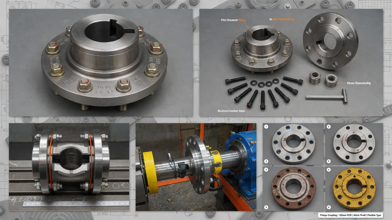
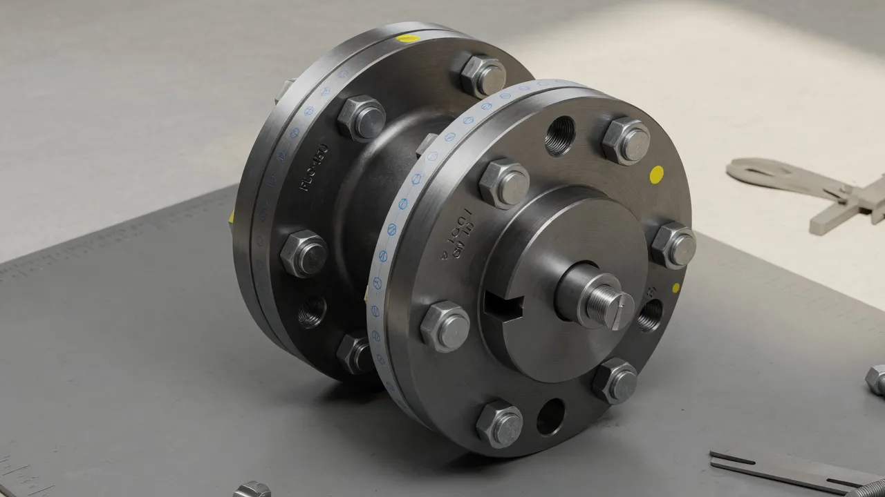
Measuring a shaft coupling correctly for replacement is a skill that saves significant time and cost. The wrong measurement approach leads to ordering the wrong coupling ¡ª then waiting for a reorder while the machine sits idle. The right approach ¡ª knowing which dimensions matter, how to take them accurately, and what to do when a size code is not visible ¡ª gets you to the correct replacement with a single order. This guide covers the measurement procedure for the most common coupling types encountered in Australian industrial maintenance, including Fenaflex replacement spacer couplings and cast iron and steel rigid shaft couplings, with practical guidance on what to do when coupling markings are absent.
The Seven Dimensions That Define a Coupling
Dimension
Where to Measure
Tool Required
Why It Matters
Bore diameter ¡ª motor side
Hub bore ID after hub removal, or shaft OD
Micrometer or vernier calliper
Must match motor shaft exactly
Bore diameter ¡ª driven side
Hub bore ID or driven shaft OD
Micrometer or vernier calliper
Must match pump/gearbox shaft
Hub outer diameter (OD)
Maximum OD of the hub body
Vernier calliper or tape measure
Confirms coupling size code
Flange outer diameter
Maximum OD of the coupling flange face
Vernier calliper
Guard clearance check
Bolt circle diameter (PCD)
Centre-to-centre of diametrically opposite bolt holes ¡Á 2
Vernier calliper or ruler
Must match for bolted couplings
Number and diameter of bolt holes
Count and measure hole ID
Vernier calliper
Bolt specification
DBSE (axial gap)
Gap between shaft faces with coupling assembled
Vernier calliper or feeler gauges
Critical for spacer and flexible couplings
Step-by-Step Measurement Procedure
1
Isolate the Machine and Remove the Coupling GuardLock out and tag out. Remove the coupling guard completely and set it aside. Clean all coupling surfaces that will be measured ¡ª remove paint, rust scale, or grease that could affect measurement accuracy.
2
Check for Any Visible Markings FirstBefore measuring, inspect all hub faces, flange ODs, and guard surfaces for stamped, cast, or labelled size codes or part numbers. Even partial markings (e.g. ‘F1’ or ‘125’ on a tyre element) may be enough for a cross-reference. Photograph all markings with a smartphone before proceeding.
3
Measure Shaft DiametersFor each shaft, measure the OD at the point where the hub bore sits. Measure at two positions 90¡ã apart and at two axial positions to check for taper or oval wear. Record to 0.01 mm. Note whether each shaft has a keyway ¡ª measure keyway width and depth if present, or confirm whether it is a Woodruff (semicircular) or parallel key.
4
Measure Coupling OD, Flange OD, and Hub LengthWith the coupling guard off and the coupling in place, measure the maximum outer diameter of the coupling assembly (the tyre OD for flexible types, or the flange OD for rigid types). Measure the hub barrel length from the shaft face to the inner edge of the flange. Record all values.
5
Measure Bolt Circle and Count BoltsFor bolted couplings, measure the centre-to-centre distance across diametrically opposite bolt holes ¡ª this is the bolt circle diameter (PCD). For odd numbers of bolts (e.g. 3 or 5), use the dimension from one hole to the centre of the coupling, then double it. Count the number of bolt holes and measure hole diameter. Record bolt material and head size if readable.
6
Measure DBSE with the Coupling AssembledWith the coupling assembled and the shafts in their operating position, insert a vernier calliper or feeler gauge into the gap between the two hub faces or shaft ends and measure the axial distance. For spacer couplings, the DBSE is the overall length of the spacer tube plus both hub face-to-shaft-end distances. Record to 0.5 mm ¡ª DBSE is not a precision measurement but must be within 2¨C3 mm of the replacement coupling’s specification.
When No Markings Are Visible ¡ª Identification by Dimension
If no coupling markings are visible, compile the measurements from steps 3¨C6 into a dimensional summary and send it to our engineering team at [email protected]. For the most common coupling families in Australian service (F-type flexible tyre, L-series jaw, rigid flange RFC series, and Fenaflex equivalent), a dimensional summary is sufficient for cross-reference in most cases. Include clear photographs of all visible surfaces.
Coupling Family
Key Identifying Dimensions
Cross-Reference Method
F-type flexible tyre (Fenaflex, Dodge Para-Flex)
Tyre OD, hub flange OD, hub bore range
Tyre OD is the primary identifier ¡ª check against F40¨CF250 dimensional table
L-series jaw coupling (Lovejoy, T-B, Rexnord)
Coupling OD, jaw pocket depth, hub bore range
Coupling OD is the primary identifier ¡ª maps directly to L-series size code
Rigid flange coupling (Flender, Bibby, own-brand)
Flange OD, PCD, bolt count, bore range
PCD and bolt count together identify the size code
Chain coupling (Falk Shear-Flex, TB Wood)
Coupling OD, chain pitch, bore range
Chain pitch + bore range identifies size
Frequently Asked Questions
What measurements do I need to identify a coupling for replacement?+
The minimum measurements to identify a standard coupling for replacement are: overall coupling outer diameter (OD); bore diameter of each hub (motor side and driven side); hub length; flange outer diameter and thickness (for rigid flange couplings); bolt circle diameter (PCD) and number of bolt holes (for bolted couplings); and the axial gap between hub faces (DBSE). For flexible tyre couplings, also measure the tyre element outer diameter and width. Send these measurements to [email protected] for an immediate cross-reference against our product range.
How do I measure the bore of a coupling hub without removing it from the shaft?+
If the coupling hub is fitted to the shaft, measure the shaft diameter at the same point with a vernier calliper or micrometer ¡ª the bore diameter matches the shaft diameter within the fit tolerance. If the shaft has a keyway, add the key height protruding above the shaft surface to get the approximate hub bore diameter. For a more precise bore measurement, the hub must be removed from the shaft and the bore measured directly with an internal bore gauge or an expanding mandrel gauge.
What is the DBSE and why does it matter for coupling replacement?+
DBSE (Distance Between Shaft Ends) is the axial gap between the two shaft faces in the assembled drive. For flexible couplings, the DBSE must match the coupling’s specified axial gap ¡ª the coupling element is designed to operate at this gap and will be over-compressed or over-stretched at other gaps. For spacer couplings, the DBSE defines the spacer tube length and must match the required maintenance clearance for seal or impeller access. Measure DBSE with the machine isolated and the shafts in their normal operating position.
Do I need to match the bolt circle diameter exactly for a coupling replacement?+
For rigid flange couplings and bolted flexible couplings, the bolt circle diameter (PCD) and bolt hole size must match exactly ¡ª mismatched PCDs mean the replacement cannot be assembled with the existing coupling hardware or the opposing hub. Flexible tyre couplings (F-type) connect through the tyre element rather than direct bolting between hubs, so the PCD of the tyre retention system is less critical than the tyre seat diameter and hub flange OD. Always provide PCD and bolt count when ordering a rigid coupling replacement.
Can I replace a metric coupling with an imperial one of similar dimensions?+
Yes, provided the bore, torque rating, and critical interface dimensions match. In Australian industry, both metric and imperial coupling sizes exist in service ¡ª particularly on older equipment imported from North America or from pre-metrication installations. Most major coupling manufacturers publish metric-to-imperial cross-reference tables. Provide the key dimensions (bore diameter, coupling OD, torque rating) and our team will identify a suitable replacement in either system.
Need Expert Coupling Advice?
Our engineering team in Condell Park NSW is ready to help ¡ª free of charge.