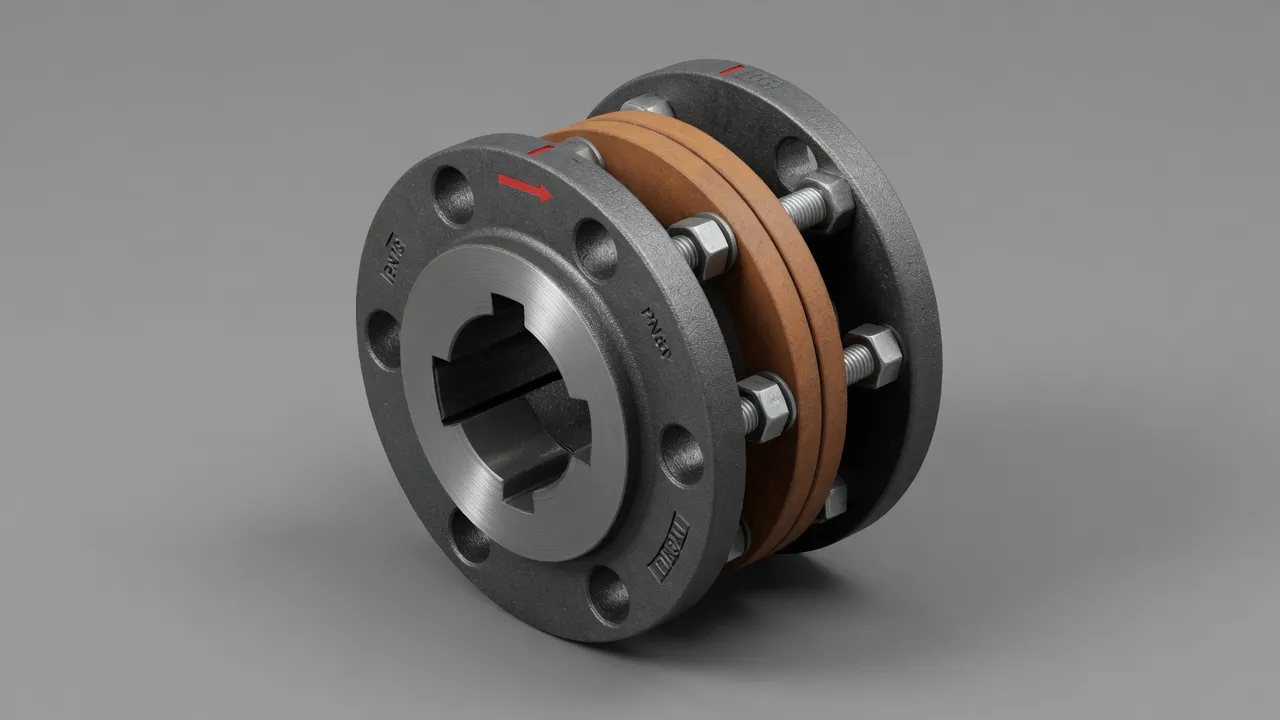
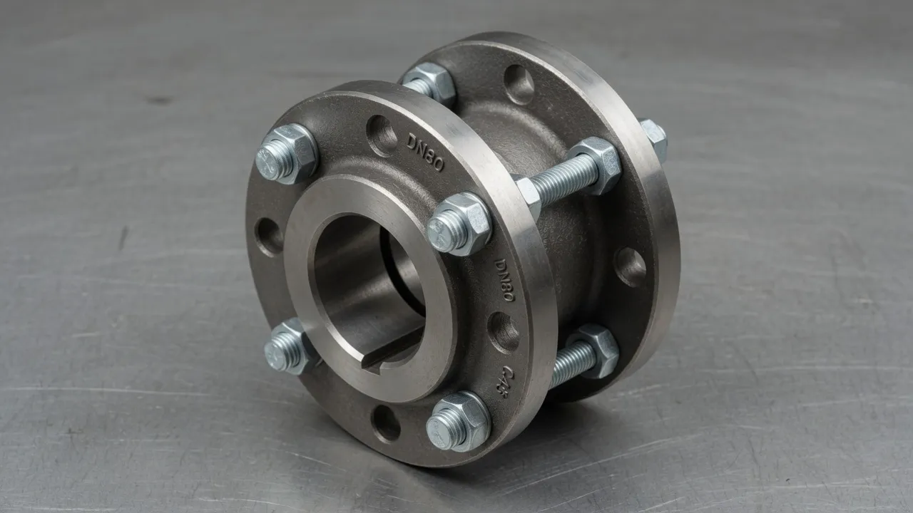
Steel mill drives sit at the extreme end of the coupling selection spectrum — the highest torques, the most demanding duty cycles, the most severe thermal environments, and the least tolerance for unplanned stoppages of any industrial application. A rolling mill stopped for a coupling failure during production loses hundreds of thousands of dollars in delayed production per hour, and the replacement coupling must be available, correctly specified, and rapidly installed. At Ever Power Flange Couplings Australia, we supply heavy-duty shaft couplings and EP-JZM diaphragm couplings to steel and metal processing facilities across Australia, with engineering support for the torsional and thermal analysis that these demanding applications require.
The Steel Mill Drive Environment — What Makes It Different
Four characteristics of steel mill drives place them in a different engineering category from all other industrial coupling applications:
Extreme Torque Levels
A modern hot rolling mill roughing stand can transmit 20,000–500,000 Nm depending on mill width and reduction per pass. At these torque levels, hub material is invariably forged alloy steel (42CrMo4 or equivalent), bore connections are shrink-fit or hydraulic expansion type (keyways would create unacceptable stress concentrations at these torques), and bolt circles use Grade 12.9 fasteners in precision-bored holes. No standard catalogue coupling meets these requirements without engineering customisation.
Reversing and Shock Loading
Reversing rolling mill stands change the direction of roll rotation between passes — applying not just a torque reversal but a combined reversal and impact as the slab re-engages the rolls. This bi-directional peak torque requirement means the coupling must be rated for full torque in both directions simultaneously, and the service factor must account for impact loading on engagement. Gear couplings and diaphragm couplings handle reversing loads well; elastomeric couplings are generally not rated for sustained bi-directional high-torque duty.
Thermal Environment
Hot rolling mills process steel at temperatures of 900–1,200°C. Radiant heat from the workpiece and scale heating raise the ambient temperature in the mill building to 40–60°C near the drives. Coupling elements must operate continuously at these ambient temperatures — which eliminates standard polyurethane and natural rubber elastomers and makes metallic coupling designs (diaphragm, gear, disc) the standard in high-radiant-heat environments.
Continuous High-Duty Operation
Steel mills operate in continuous campaigns — sometimes for weeks without a planned maintenance shutdown. Coupling designs for mill drives must provide the longest possible time between maintenance interventions and must accommodate any unplanned downtime within a minimum repair window. Diaphragm couplings with no wear elements and no lubrication requirement are the maintenance-minimum solution for drives where access during production is impossible.
Coupling Types Used in Steel Plant Drives
Drive Location
Torque Range
Coupling Type
Key Requirement
Motor to gearbox (main mill drive)
5,000–50,000 Nm
Diaphragm coupling or gear coupling
Thermal growth accommodation; reversing rating
Gearbox to roll (floating spindle)
20,000–500,000 Nm
Cardan shaft with universal joints
Large angular offset from roll gap adjustment
Roll shop machine tool drives
50–2,000 Nm
Heavy-duty flange coupling or disc coupling
Precision torque transmission; zero backlash
Cooling pump drives
100–5,000 Nm
F-type flexible tyre coupling
Standard pump application; corrosion resistance
Hydraulic system pump drives
100–3,000 Nm
Flexible tyre or jaw coupling
No lubrication in hydraulic environment
Overhead crane drives
200–10,000 Nm
Heavy-duty flange or snake spring coupling
Shock loads from load pick-up; reversing
Scale breaker drive
5,000–30,000 Nm
Heavy-duty flexible flange coupling
Very heavy shock from scale fracture impulse
Specifying a Diaphragm Coupling for a Hot Mill Auxiliary Drive
For auxiliary drives in a hot rolling mill environment — hydraulic AGC cylinder drives, roll bending pump sets, and roll cooling system motors — the EP-JZM diaphragm coupling provides the maintenance-free, high-temperature-rated performance that the environment demands. Key specification parameters for hot mill auxiliary drives:
1
Temperature RatingVerify that the coupling’s maximum continuous operating temperature covers the worst-case ambient temperature in the drive’s location. Near the rolling line, ambient temperatures of 60°C are common. Stainless steel diaphragm elements are rated to 300°C — well above any realistic ambient in the mill building auxiliary areas.
2
Axial Movement AccommodationHot mill structures grow axially as they reach operating temperature from cold start. The coupling must accommodate this axial movement without transmitting thrust loads to the connected motor or pump bearings. Specify the EP-JZM series with the axial movement capacity confirmed against the calculated thermal growth for the specific drive location.
3
Service Factor for Mill EnvironmentApply a minimum service factor of 2.0 for smooth auxiliary pump drives in a hot mill — higher than the standard 1.5 for equivalent external pump drives, to account for vibration, thermal shock, and the elevated maintenance cost of any failure in this environment.
4
Documentation and Material TraceabilitySteel plant engineering specifications typically require full material traceability for critical drive components. Specify material certificates to the relevant standard (AS, DIN, or EN) for all hub and diaphragm materials when ordering for steel plant applications.
Frequently Asked Questions
What type of coupling is used on a rolling mill spindle?+
Rolling mill spindles use heavy-duty gear couplings or Cardan shaft (universal joint) assemblies capable of transmitting hundreds of thousands of Newton-metres while accommodating the large angular offsets inherent in roll gap adjustment. For the motor-to-gearbox connection, heavy-duty flange couplings or diaphragm couplings are used depending on the torque level and whether maintenance-free operation is specified. The combination of extreme torque, reversing loads, and continuous operating duty makes steel mill drives the most demanding coupling application in industrial engineering.
What service factor applies to a steel mill coupling?+
Steel mill coupling service factors range from 2.5 to 4.0 depending on the mill type and rolling operation. Hot rolling mills with reversing stands apply the highest service factors — the combination of reversing torque, work-roll bite impact, and the thermal shock of hot slab contact produces torque peaks that can reach 4–5 times the nominal running torque. Cold rolling mills with continuous non-reversing operation apply lower service factors (2.5–3.0) but demand higher precision in torque transmission consistency for gauge control.
How does thermal growth affect coupling selection on a hot rolling mill?+
Hot rolling mill equipment operates at elevated ambient temperatures from radiant heat of the workpiece, and the mill housings and drive components grow thermally during production. The coupling must accommodate the resulting axial and angular shaft movement without transmitting thermal growth forces to the motor or gearbox bearings. Diaphragm couplings with their generous axial movement accommodation (±3–6 mm) are preferred over disc couplings (±0.5–2 mm) for hot mill applications where thermal growth is significant.
Can a flexible elastomeric coupling be used on a steel mill?+
Flexible elastomeric couplings (tyre, spider, pin-bushing types) are not typically used in the main drive train of a rolling mill — the torque levels, reversing loads, and thermal environment exceed the practical limits of elastomeric designs. However, elastomeric couplings are used on auxiliary drives within steel plants: cooling pump drives, hydraulic unit pump connections, roll shop machine tool drives, and other support equipment that operates at conventional industrial torque levels in better-controlled environments.
What is a floating shaft coupling on a rolling mill?+
A floating shaft (or articulated spindle) on a rolling mill is an intermediate shaft between the gearbox output and the roll, connected at each end by a universal joint (Cardan coupling). This assembly allows the roll gap to be adjusted — raising and lowering the work roll — while maintaining continuous torque transmission from the gearbox to the roll. The universal joints accommodate the angular change as the roll position varies, and the floating shaft spans the distance between gearbox output and roll journal. These are the most highly loaded couplings in any industrial application.
Need Expert Coupling Advice?
Our engineering team in Condell Park NSW is ready to help — free of charge.