Description
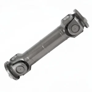
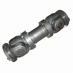
The SWC-WH is the without-flex (rigid) configuration of the welded-yoke universal coupling family — no telescoping intermediate spline, maximum torsional stiffness, and substantial parallel-offset capability through dual Hooke’s joint geometry. The without-flex design suits applications where the input and output shafts run parallel but offset, transmitting power between staggered shaft centrelines without requiring axial movement compensation. Rolling mill offset drives, hoisting equipment, and material handling lines with parallel-shaft arrangement all benefit from this heavy duty shaft coupling configuration.
SWC-WH Specifications and Dimensional Range
The SWC-WH range covers gyration diameters from 100 mm to 490 mm. Maximum operating angle is 25 degrees through each Hooke’s joint, providing 25-degree parallel offset capability through the double-joint geometry. Nominal torque ratings match the equivalent SWC-BH and SWC-CH sizes for any given gyration diameter. The defining characteristic is the absence of a telescoping element, which delivers maximum torsional stiffness at the cost of zero axial compliance.
| Model | Gyration Ø D (mm) | Nominal Torque Tn (kN·m) | Fatigue Tn Tf (kN·m) | Flex Angle β (°) | Bore D₂ (mm) | Lmin (mm) |
|---|---|---|---|---|---|---|
| SWC100WH | 100 | 1.25 | 0.63 | ≤25° | 20–44 | 243 |
| SWC150WH | 150 | 4.5 | 2.25 | ≤25° | 30–65 | 320 |
| SWC200WH | 200 | 16 | 8.0 | ≤25° | 40–95 | 390 |
| SWC250WH | 250 | 35 | 17.5 | ≤25° | 55–115 | 460 |
| SWC285WH | 285 | 71 | 35.5 | ≤25° | 75–130 | 490 |
| SWC315WH | 315 | 112 | 56 | ≤25° | 85–150 | 550 |
| SWC390WH | 390 | 224 | 112 | ≤25° | 100–175 | 620 |
| SWC490WH | 490 | 450 | 225 | ≤25° | 135–220 | 740 |
The fixed installed length is the only dimensional adjustment available — there is no telescoping range. Installations using SWC-WH must therefore maintain the design shaft-centre distance throughout the operating temperature and load range. Thermal growth and foundation settlement must be accommodated by the supporting equipment design rather than the coupling.
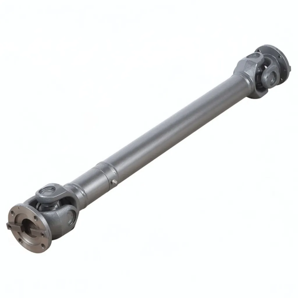
SWC-WH Without Flex Welding Type Universal Coupling – welded yoke design, no telescoping element. Ever Power Flange Couplings Australia Ltd.
What Distinguishes the SWC-WH from Other Universal Joint Types
The without-flex (rigid) design philosophy distinguishes the SWC-WH from the flex variants in the SWC welding-type family. Where the BH, CH, and DH variants incorporate a telescoping splined intermediate shaft that accommodates axial movement during operation, the WH variant uses a fixed-length intermediate component. The rigid construction delivers maximum torsional stiffness because no spline-fit clearance contributes to wind-up under load reversal.
The rigid configuration suits applications where the shaft-centre distance is dimensionally stable throughout the operating envelope — installations without significant thermal axial growth, on rigid foundations, with structural arrangements that prevent shaft movement. Multi-pass rolling mill offset drives, hoist drives, and rigid material handling installations match this profile. For applications with axial movement, the flex variants (BH, CH, DH) are the correct choice.
Parallel Offset Capability Through Dual Hooke’s Joints
The two Hooke’s joints (universal joints) operate at equal angles in opposite directions, generating a parallel offset between the input and output shafts proportional to the joint angle and the intermediate shaft length. This geometric relationship allows the SWC-WH to transmit power between parallel shafts whose centrelines are offset by significant distances — up to 200 mm or more at the larger size classes. This parallel-offset capability is the defining engineering benefit of the without-flex variant.
Construction and Material Specification
Material specification matches the SWC welding-type range: 35CrMo alloy steel forging, full quench-and-temper heat treatment, induction-hardened trunnion journals to HRC 58-64. Without the telescoping splined intermediate shaft, the SWC-WH construction is simpler and the bearing loading more predictable — there are no spline-engagement forces contributing to bearing loads.
Sealed needle roller bearings are pre-lubricated at assembly. The yoke-to-shaft weld preparation follows the standard procedure for the SWC welding-type range. The shorter overall installed length compared to flex variants simplifies field installation logistics — the assembly is lighter and easier to position during commissioning.
No telescoping spline contributes to wind-up under load reversal. Highest torsional stiffness in the SWC welding-type range. Suitable for applications requiring precise output shaft position retention under reversing torque.
Dual Hooke’s joint geometry transmits power between staggered parallel shaft centrelines. Up to 25-degree joint angle generates substantial offset capability — common requirement on multi-pass rolling mill drives and hoist installations.
Same welded-yoke stiffness as the flex variants. Eliminates bolt-circle tolerance chain. Suitable for high-frequency reverse-load applications including crane hoist drives and rolling mill offset spindles.
Same material and heat treatment as the SWC flex variants. Trunnion cross and bearings interchangeable with equivalent BH, CH, and DH sizes.
Pre-lubricated at assembly. Simplified bearing loading without spline-engagement forces from telescoping mechanisms.
No axial travel range — install at design shaft-centre distance. Suits applications without thermal growth or foundation settlement movement during operation.
Industrial Applications Across Heavy Industry
SWC-WH applications focus on parallel-offset drives where the input and output shaft centrelines are staggered but the shaft-centre distance is dimensionally stable. Hoisting equipment, multi-pass rolling mill drives, and material handling lines with parallel shafts all match this profile.
Crane Hoist Drives and Hoisting Equipment
Overhead crane hoist drives and dedicated hoisting equipment use SWC-WH couplings between the hoist motor gearbox and the drum drive shaft. The parallel-offset capability allows the gearbox and drum to occupy independent shaft positions within the crane structural envelope. The rigid configuration avoids the unwanted axial movement that a flex variant could introduce under hoist load — important for precise load positioning in steel mill and shipyard cranes.
Multi-Pass Rolling Mill Offset Drives
Certain rolling mill configurations use a single drive motor to power multiple work rolls through staggered shaft connections. The SWC-WH parallel-offset capability allows the drive shaft to bridge between the motor output and the various roll positions without requiring independent motors for each roll. This industrial shaft coupling configuration is common on older rolling mill installations that are being modernised with new drive equipment.
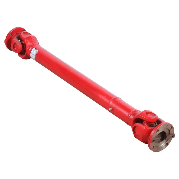
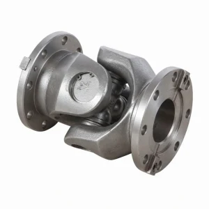
SWC-WH rigid yoke assembly – no telescoping element, maximum torsional stiffness for parallel-offset drives.
Selecting the Correct SWC-WH Size for Your Drive
Choose SWC-WH when your application has a parallel shaft-centre offset and dimensionally stable shaft-centre distance throughout the operating range. Verify that thermal growth, foundation settlement, and load-induced shaft movement will all remain within negligible levels — the without-flex variant has zero axial compliance. If any meaningful axial movement is expected, specify a flex variant (BH, CH, or DH) appropriate to the expected travel range.
Calculate the required joint angle from the parallel offset distance and the intermediate shaft length. Both joints must operate at the same angle in opposite directions for constant-velocity power transmission. Verify the calculated joint angle stays below the 25-degree rated maximum with appropriate safety headroom.
Installation, Operation, and Maintenance Best Practice
Installation requires precise positioning to maintain the design shaft-centre distance throughout the operating range. Foundation rigidity and equipment-mounting precision are more critical for SWC-WH than for flex variants because there is no telescoping element to absorb post-installation dimensional changes.
Confirm equipment foundations and mounting arrangements will maintain the design shaft-centre distance throughout the operating temperature range. Any thermal growth must be accommodated by the supporting structure, not the coupling.
Measure the parallel offset between input and output shaft centrelines. Calculate the required joint angle and verify it sits within the 25-degree rated maximum with safety headroom. Adjust equipment positioning if needed before welding.
Both shaft ends machined square, free of burrs, prepared for welding per the supplied weld procedure specification.
Slide each yoke onto its shaft to the design position. Apply tack welds. Verify the trunnion cross rotates smoothly through both joints simultaneously before completing the full circumferential welds.
Run full circumferential welds in multiple passes per the supplied weld procedure. Allow controlled cooling. Post-weld heat treatment per engineering specification if required.
Run at progressively increasing speed to full operating speed. Monitor vibration and joint temperature for first 50 hours. Inspect bearings and seals at first scheduled maintenance.
OEM Cross-Reference and Order Specification
Cross-reference is available for Voith Turbo without-flex cardan shafts, Rexnord rigid universal joint couplings, and SKF parallel-offset industrial couplings. Provide the OEM model code, gyration diameter, nominal torque, parallel offset dimension, and joint angle for direct equivalent confirmation.
For replacement applications, the existing parallel offset dimension is the most important specification — small variations in offset can shift the operating joint angle significantly. Send dimensioned drawings of the existing installation, or photographs with key measurements, for our Sydney engineering team to confirm the SWC-WH equivalent before order generation.
Why Choose Ever Power Australia
Ever Power Flange Couplings Australia Ltd. stocks the commonly specified SWC-WH sizes at our Condell Park warehouse for same-day dispatch on confirmed stock orders. The without-flex variant is less commonly stocked than the flex equivalents — for less common sizes, verify availability before quoting. Cross-reference work for Voith, Rexnord, and SKF parallel-offset cardan shaft equivalents is included as a standard service.
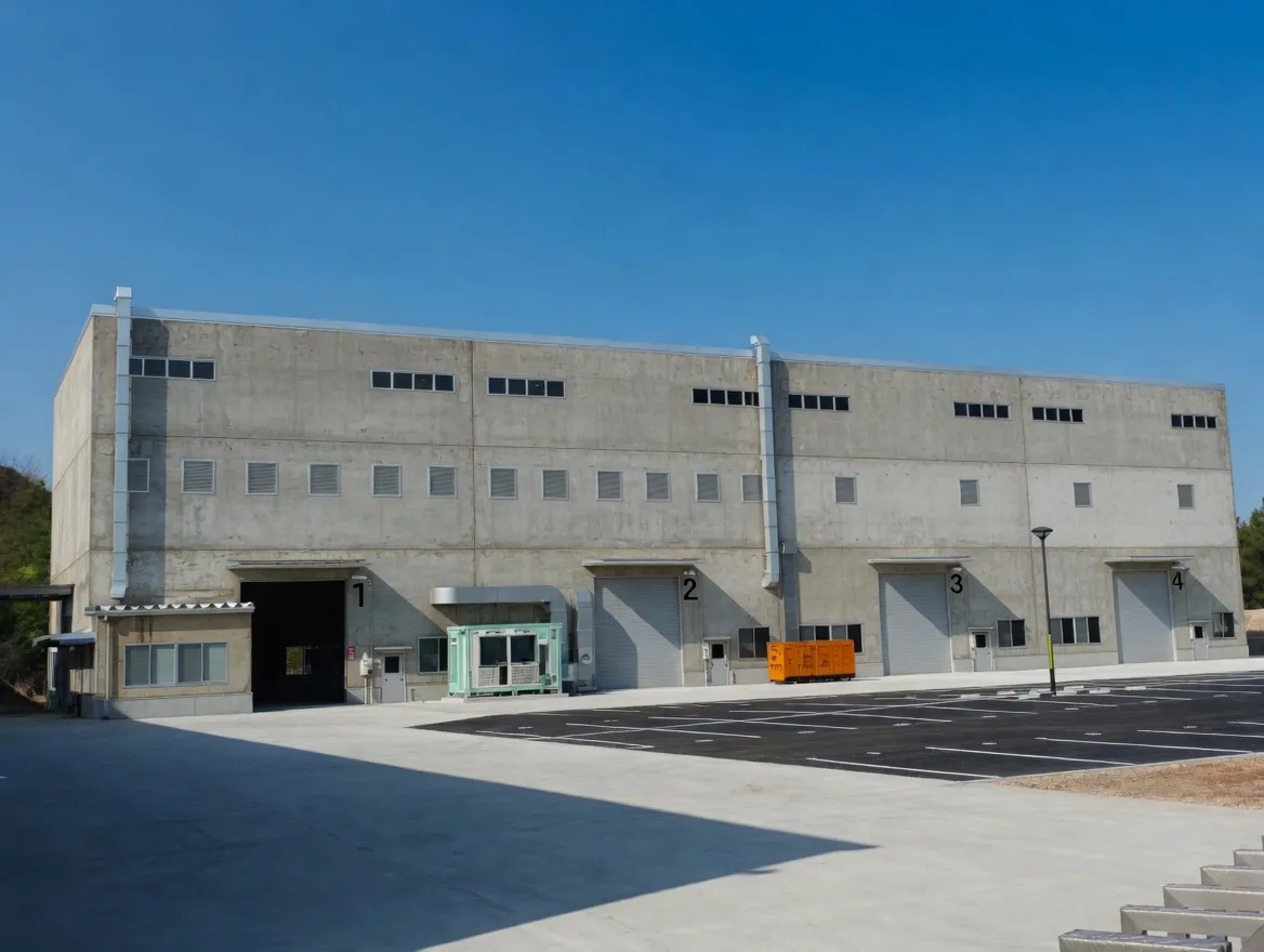
Ever Power manufacturing facility — ISO 9001 certified, 12,000 m², 108 dedicated coupling machines, 20+ years of production experience.
Every order placed with our Sydney team is backed by full material traceability, dimensional inspection certificates on request, and direct access to the engineers who specified, machined, and packed your coupling. We do not subcontract technical support — when you phone +61 2 9708 3322 during NSW business hours, you reach the people who actually know the product.
Frequently Asked Questions
Quick answers from our Sydney technical team. Contact us for application-specific guidance.
1. What does ‘without flex’ mean for the SWC-WH? +
2. Can the SWC-WH handle axial thermal growth between motor and driven machine? +
3. What parallel offset capability does the SWC-WH provide? +
4. Is the SWC-WH torque rating different from SWC-BH? +
5. How quickly can I receive an SWC-WH from your Sydney warehouse? +
Request a Quote — Sydney NSW Stock
Tell us your motor power, shaft diameter, and operating environment. Our New South Wales coupling team confirms availability and pricing within one business day, with same-day dispatch on standard sizes from Condell Park.
Ever Power Flange Couplings Australia Ltd. · 27 Harley Crescent, Condell Park NSW 2200 · [email protected]