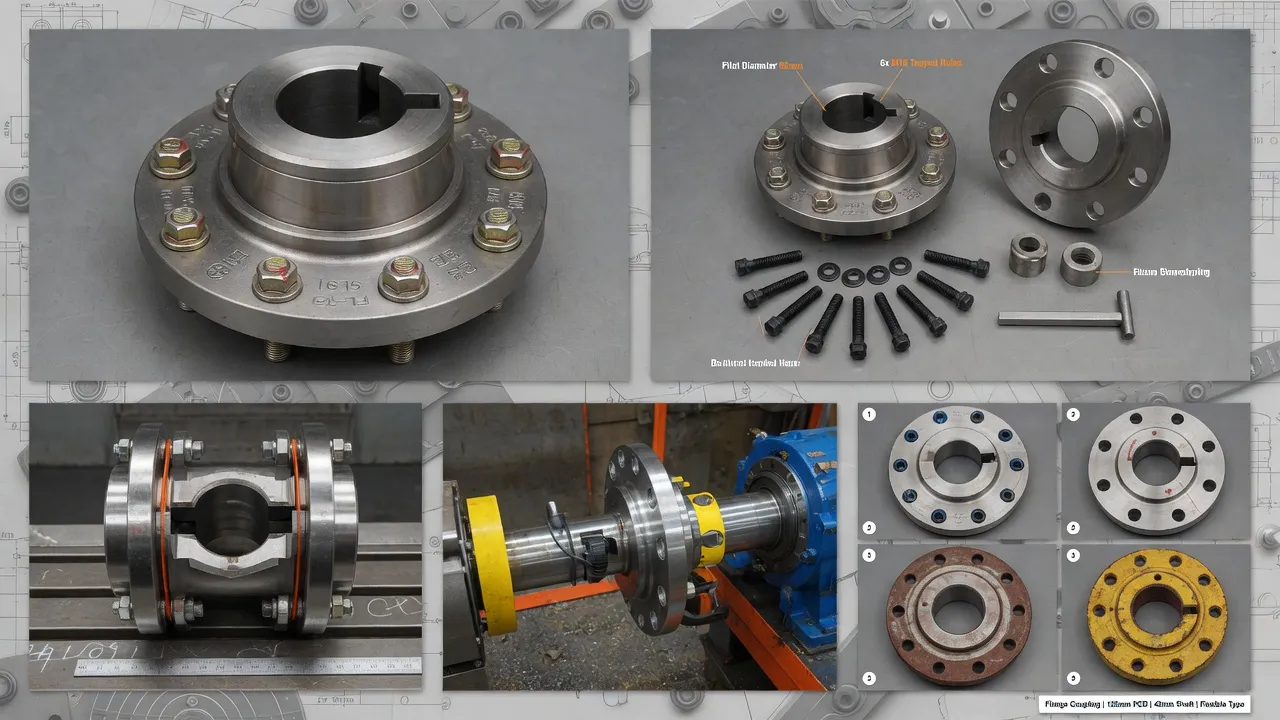
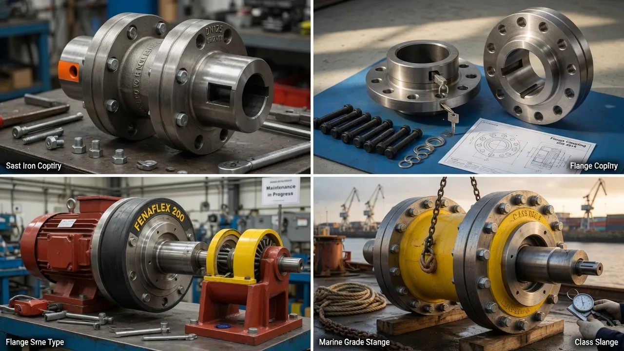
Torsional analysis is the engineering process of calculating the torsional natural frequencies of a rotating drivetrain and determining whether any of them fall in the operating speed range at excitation amplitudes that could cause fatigue failure. For most standard motor-pump drives, torsional analysis is not required ¡ª the smooth-running motor and centrifugal pump combination does not produce significant torsional excitation. But for drives involving diesel engines, reciprocating compressors, variable speed drives over wide speed ranges, or large turbomachinery, torsional analysis is not optional ¡ª it is the engineering foundation on which the coupling specification is built. The marine flange coupling range and the EP-JZM heavy machinery diaphragm coupling are the two Ever Power products most frequently specified based on torsional analysis results, with coupling stiffness selected specifically to place the system’s natural frequency outside the excitation frequency range of the connected engine or compressor.
What Torsional Vibration Is ¡ª and Why It Is Different from Lateral Vibration
Lateral vibration is the side-to-side or up-and-down movement of a rotating shaft measured in millimetres ¡ª it is what a vibration meter measures at a bearing housing. Torsional vibration is the cyclic variation in shaft angular velocity superimposed on the mean rotation speed ¡ª it is measured in degrees or radians of angular oscillation. A shaft in torsional vibration is rotating at its mean speed while simultaneously oscillating rotationally at a much smaller amplitude.
Standard vibration meters do not measure torsional vibration directly. Specialised torsional measurement instruments (laser Doppler vibrometers, rotary encoders with high-resolution counters, or strain-gauged shafts with telemetry) are required for direct measurement. In practice, the consequences of torsional resonance ¡ª coupling fatigue, shaft cracking, and keyway fractures ¡ª are often the first detectable indication that a torsional problem exists.
Systems That Require Torsional Analysis
Diesel Engine Drives
Diesel engines produce torsional excitation at the firing frequency (n_cyl ¡Á RPM/120 for 4-stroke) and its harmonics. The excitation force at each harmonic decreases with harmonic order but can still be significant at harmonics 2¨C6 for a 6-cylinder engine. Any coupling connecting a diesel engine to a gearbox, generator, or pump requires a torsional analysis to verify that no resonance falls in the continuous operating speed range at damaging amplitude.
Reciprocating Compressors and Pumps
Reciprocating machines produce pulsating torque at the stroke frequency and harmonics. A single-cylinder compressor produces the most severe pulsation; multi-cylinder machines have more complex but often lower-amplitude excitation patterns. The coupling between the motor and a reciprocating compressor must be soft enough to detune from the pulsation frequency, or stiff enough to push the natural frequency above the highest significant harmonic.
Variable Speed Drive Systems
A VSD-driven system passes through a continuous range of excitation frequencies as the motor speed varies. At some speed within the range, the excitation frequency will coincide with the system’s torsional natural frequency ¡ª producing resonance. The torsional analysis must cover the entire VSD speed range, identify all resonance crossings, and confirm that the vibratory torque amplitude at each crossing is below the fatigue limit of the coupling and shaft.
The Torsional Analysis Process ¡ª Step by Step
1
Collect System ParametersGather rotational inertia data for all rotating components: motor rotor (from motor datasheet), coupling assembly (from coupling supplier), driven machine (from machine datasheet or calculation). Collect shaft geometry between coupling flanges. For the excitation source, collect the torque variation as a function of crank angle (for reciprocating machines) or the switching frequency characteristics (for VSDs).
2
Build the Torsional ModelRepresent the drivetrain as a lumped-parameter model ¡ª a series of inertia discs connected by torsional springs and dampers. The coupling provides the torsional spring (stiffness kt) and damper (damping coefficient ct) between the motor inertia and driven machine inertia. This model is solved analytically or numerically to find the natural frequencies.
3
Identify Resonance CrossingsPlot the natural frequencies on a Campbell diagram alongside the excitation frequency as a function of operating speed. Each point where an excitation frequency line crosses a natural frequency line is a resonance crossing. For each crossing in the operating speed range, calculate the vibratory torque amplitude using the system’s Q-factor (amplification factor at resonance).
4
Evaluate Against Fatigue LimitsCompare the vibratory torque amplitude at each resonance crossing to the fatigue limit of the coupling element and the shaft. If the amplitude exceeds 80% of the fatigue limit at any crossing in the continuous operating range, a design change is required ¡ª most commonly, changing the coupling torsional stiffness to move the natural frequency.
5
Confirm and DocumentOnce the analysis confirms that all resonance crossings are either outside the continuous operating range or below the fatigue limit, document the analysis results and include them in the equipment technical file. For marine and oil and gas applications, submit to the relevant classification society for review.
Coupling Stiffness Adjustment ¡ª The Primary Engineering Lever
Intervention
Effect on Natural Frequency
When to Use
Softer elastomeric element (lower Shore hardness)
Decreases ¡ª pushes resonance below operating range
When resonance is within the lower part of the operating speed range
Harder elastomeric element (higher Shore hardness)
Increases ¡ª pushes resonance above operating range
When resonance is within the upper part of the operating speed range
Add flywheel or increase driven machine inertia
Decreases ¡ª lowers natural frequency
When coupling stiffness adjustment alone is insufficient
Change coupling type (e.g. tyre to disc)
Can increase significantly ¡ª disc coupling has much higher stiffness
When a large upward shift in natural frequency is needed
Set VSD skip frequency (speed exclusion zone)
Avoids resonance speed ¡ª does not change natural frequency
When resonance crossing cannot be eliminated but can be avoided in operation
Frequently Asked Questions
When is torsional analysis mandatory for a coupling specification?+
Torsional analysis is mandatory or strongly recommended in the following situations: all reciprocating engine or compressor drive couplings where the cylinder firing frequency or harmonics could excite torsional resonance; turbomachinery (turbines, large centrifugal compressors) where classification societies or API standards require it; marine propulsion drives where Lloyd’s, DNV-GL, or other classification bodies require torsional analysis documentation; VSD-driven systems spanning a wide speed range where multiple resonance crossings may exist in the operating range; and any system that has experienced unexplained coupling or shaft fatigue failures.
What inputs are needed for a torsional analysis?+
A torsional analysis requires: motor rotational inertia (kg¡¤m2) and rated torque; coupling torsional stiffness (Nm/rad) and damping coefficient; driven machine rotational inertia (kg¡¤m2); shaft diameter and length between coupling flanges; and, for reciprocating or pulsating sources, the torque variation as a function of crank angle or excitation frequency. Ever Power can provide coupling torsional stiffness and damping data for all products in our range. For marine and oil and gas applications, we provide this data in the format required by the relevant classification society.
What does a torsional analysis output show?+
The primary output is a Campbell diagram ¡ª a plot of torsional natural frequency versus operating speed, overlaid with the excitation frequencies of the drive system at each speed. Resonance crossings appear where excitation frequency lines intersect the natural frequency line. The analysis then calculates the vibratory torque amplitude at each resonance crossing and compares it to the coupling’s and shaft’s fatigue limits. A coupling or shaft is considered safe if no resonance crossing within the continuous operating range exceeds 80% of the fatigue limit.
Can I change coupling stiffness to avoid torsional resonance?+
Yes ¡ª adjusting coupling torsional stiffness is the most common engineering intervention to avoid torsional resonance. A softer coupling (lower stiffness, lower torsional natural frequency) moves the resonance below the operating speed range. A stiffer coupling (higher stiffness, higher natural frequency) moves the resonance above the operating range. The specific stiffness change required is calculated from the analysis ¡ª and for elastomeric couplings, changing the spider or tyre element hardness grade is often sufficient to achieve the required stiffness shift without changing the coupling size.
Does a standard industrial pump coupling need torsional analysis?+
For a standard centrifugal pump driven by a squirrel-cage induction motor at fixed speed, torsional analysis is not required. The torque from a centrifugal pump is smooth and continuous with negligible excitation at discrete frequencies, and the motor produces minimal torsional excitation on the grid supply. Torsional analysis becomes necessary when the drive includes a reciprocating machine, a VSD, a diesel or gas engine, or a turbine ¡ª all of which produce periodic torsional excitation at frequencies that can excite resonance in the drive system.
Need Expert Coupling Advice?
Our engineering team in Condell Park NSW is ready to help ¡ª free of charge.