
The jaw coupling — also known as a spider coupling or claw coupling — is the most widely used elastomeric coupling type in Australian industrial maintenance. Its simplicity is its greatest advantage: two hubs with interlocking jaw projections and an elastomeric spider insert between them. No bolts between the coupling halves, no lubrication, no precision assembly required. Yet despite its apparent simplicity, specifying a jaw coupling correctly requires understanding torque ratings, spider hardness, misalignment limits, and the specific demands of the connected machinery. This guide covers everything that matters about jaw coupling design, selection, and maintenance, including internal links to the LT pin coupling and NM coupling ranges that extend the jaw coupling principle to higher torque applications.
The Mechanical Principle Behind a Jaw Coupling
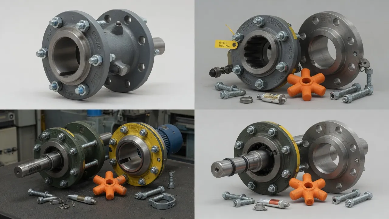
A jaw coupling consists of two identical or similar hubs, each with three or more jaw projections arranged radially around the hub bore. When the two hubs are brought face-to-face, their jaw projections interdigitate — the jaws of one hub mesh with the gaps between the jaws of the other. The elastomeric spider insert fills the gaps between all the jaw faces, creating a torque transmission path through compression of the spider lobes between opposing jaw faces.
This compression-based torque transmission is what gives the jaw coupling its distinctive characteristics. The spider material deforms elastically under load, transmitting torque while simultaneously accommodating small amounts of angular, parallel, and axial misalignment through the elastic flexibility of the lobes. The softer the spider material, the more it deforms — which means more misalignment accommodation and more vibration damping, but also lower torsional stiffness and a lower torque ceiling before the lobes begin to yield plastically.
Jaw Coupling Spider Hardness Grades — Selecting the Right Grade
80A Shore — Soft
Maximum vibration damping and misalignment accommodation. For rough-running machinery, reciprocating loads, and flexible baseplates. Lower torque ceiling — verify rating for your application. Most forgiving of misalignment.
92A Shore — Standard
The default for general industrial pump, fan, and conveyor drives. Balances damping with torque capacity. Handles typical misalignment found on grouted pump bases in normal service conditions.
98A Shore — Hard
High torsional stiffness for VSD-driven loads and applications where speed control accuracy matters. Minimal vibration damping — suitable only where alignment is tight and base is stable.
Standard Size and Performance Reference
| Coupling Size | Max Bore (mm) | Rated Torque (Nm) 92A | Peak Torque (Nm) | Angular Tol. (°) | Parallel Tol. (mm) |
|---|---|---|---|---|---|
| L035 | 9 | 3.5 | 7 | 1° | 0.25 |
| L050 | 14 | 8 | 16 | 1° | 0.38 |
| L070 | 19 | 20 | 40 | 1° | 0.50 |
| L075 | 24 | 34 | 68 | 1° | 0.50 |
| L090 | 28 | 68 | 136 | 1° | 0.63 |
| L095 | 32 | 100 | 200 | 1° | 0.63 |
| L099 | 38 | 148 | 296 | 1° | 0.75 |
| L100 | 42 | 203 | 406 | 1° | 0.75 |
| L110 | 45 | 373 | 746 | 1° | 0.75 |
| L150 | 55 | 814 | 1,628 | 1° | 1.00 |
Where Jaw Couplings Are Used in Australian Industry
The jaw coupling’s combination of no-lubrication maintenance, vibration damping, and simple spider replacement makes it the default coupling for light to medium motor-pump and motor-fan drives across a wide range of Australian industries. For larger bore sizes and higher torques where the jaw coupling’s capacity is exceeded, the LT pin coupling series provides the next step up — using steel pins with elastomeric bushings to handle significantly higher torque at the same bore diameters, while retaining the no-lubrication maintenance advantage.
| Industry | Application | Preferred Spider Grade |
|---|---|---|
| Water & Wastewater | Small centrifugal pump drives up to 30 kW | 92A polyurethane |
| HVAC | Fan and blower drives in air handling units | 80A for vibration damping |
| Food & Beverage | Mixer, conveyor, and filling machine drives | FDA-compliant PU or EPDM |
| Packaging | Light conveyor and indexing drive connections | 92A polyurethane |
| General Manufacturing | Motor to gearbox connections up to 150 Nm | 92A or 98A depending on VSD use |
How the NM Coupling Extends the Jaw Coupling Concept
The NM coupling uses the same jaw-and-spider operating principle as a standard jaw coupling but is manufactured to a heavier hub cross-section and larger overall envelope, extending the torque range to 4,500 Nm and the bore range to 100 mm. The NM coupling is commonly specified where a jaw coupling is the preferred design but the motor power or shaft diameter exceeds the standard jaw coupling range. The spider element is the same elastomeric material in the same hardness grades, and the same no-lubrication maintenance advantage applies.
Maintenance and Inspection Schedule
| Interval | Task | Indicator of Problem |
|---|---|---|
| Monthly | Listen for coupling knock or slapping noise during deceleration | Audible knock = spider worn to metal-to-metal contact |
| Quarterly | Vibration baseline reading at motor and driven machine bearings | Rising vibration trend = spider degrading or misalignment developing |
| Annually | Remove coupling guard, visually inspect spider — check for cracking, chunking, rubber dust | Any chunking or rubber debris = replace spider before next scheduled interval |
| Every 2 Years | Scheduled spider replacement regardless of visual condition (high-duty applications) | Planned replacement prevents unplanned failure |
| At any motor or pump service | Check shaft alignment with laser tool; re-torque motor hold-down bolts | Misalignment found = correct before fitting new spider |
Frequently Asked Questions
Need Expert Coupling Advice?
Our engineering team in Condell Park NSW is ready to help — free of charge.