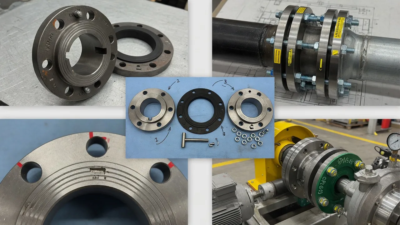
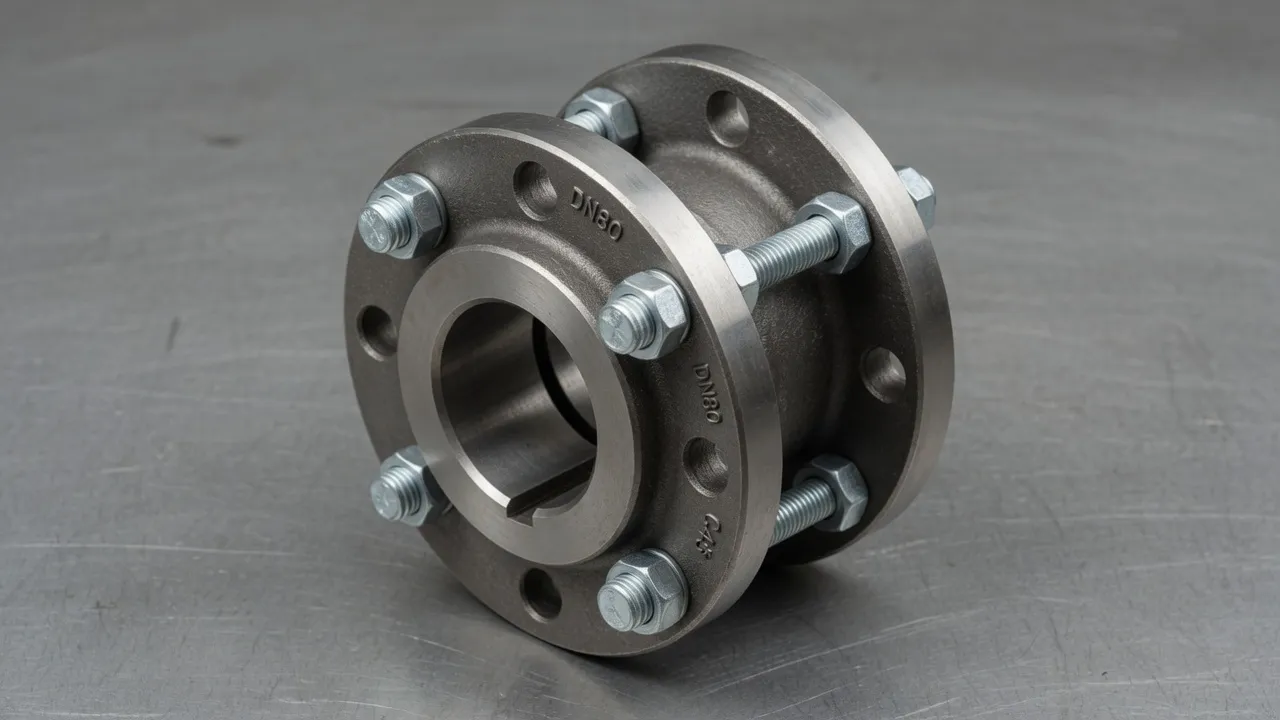
Shaft alignment before coupling installation is not a recommendation — it is a mechanical necessity for any motor-driven drivetrain that is expected to achieve rated service life. The question of whether alignment is necessary has the same answer regardless of coupling type, motor power, or application: yes, always. What changes between applications is the alignment method, the required accuracy, and the consequences of getting it wrong. For an EP-YL rigid flange coupling on a precision test rig, alignment to 0.02 mm TIR is mandatory. For a drop-out spacer coupling on a pump whose seal will be replaced twice a year, alignment to 0.05 mm is the appropriate standard. In both cases, alignment before installation is essential and the cost of skipping it — in shortened service life, increased maintenance frequency, and unplanned shutdowns — far exceeds the time invested in doing it.
Why Alignment Is Non-Negotiable — The Engineering Reason
When two shafts are not co-linear, a coupling connecting them must continuously deform as it rotates to bridge the angular or positional gap between them. For a rigid coupling, this deformation is impossible — the coupling is rigid, so the shafts themselves must deform, transmitting the resulting bending forces to the motor and driven-machine bearings as cyclic radial loads. For a flexible coupling, the elastomeric element deforms to bridge the gap, but the deformation energy is partly transmitted to the bearings as a restoring force.
In both cases, the bearing experiences a radial load above its rated working value — a continuous, cyclic overload that accumulates fatigue damage. The damage accumulation rate follows the bearing life equation: L10 ∝ (C/P)³. A 25% increase in radial load (from misalignment) reduces ball bearing life to (1/1.25)³ = 51% of its rated value. This is not a theoretical risk — it is the measured outcome in plants where alignment is not maintained, expressed as motor bearings replaced at half their expected service life.
Alignment Accuracy Required by Coupling Type
Coupling Type
Angular (°)
Parallel (mm)
Consequence of Exceeding Tolerance
Rigid flange coupling
≤ 0.03°
≤ 0.03 mm
Direct bearing overload — no compliance in coupling to absorb forces
Flexible tyre coupling (general)
≤ 0.10°
≤ 0.10 mm
Elastomeric element fatigue, bearing overload
Disc coupling (servo grade)
≤ 0.05°
≤ 0.05 mm
Disc pack fatigue, positioning error
Spacer coupling (flexible ends)
≤ 0.15° per end
≤ 0.15 mm
Element fatigue, overhung bearing load increase
Universal coupling (Cardan shaft)
≤ 1.0° per joint
N/A — not applicable
Velocity non-uniformity, vibration at 2× RPM
The Alignment Procedure in Practice
1
Correct Soft-Foot Before Any Alignment AttemptWith all hold-down bolts finger-tight, use feeler gauges between each motor foot and the baseplate. Any gap above 0.05 mm at any foot is soft-foot and must be corrected by shimming before proceeding. Attempting alignment without correcting soft-foot produces readings that change when bolts are tightened — the alignment can never be finalised.
2
Mount Laser Alignment System HeadsFix the laser emitter to one coupling hub and the detector to the other. Ensure both heads are clamped firmly — any movement during the sweep will produce erroneous readings. Input machine dimensions (foot-to-foot distance, feet positions relative to coupling centre) into the alignment software.
3
Sweep and CalculateRotate both shafts through the required arc (typically 60°–180° depending on system) while recording laser position. The software calculates angular and parallel misalignment and displays the shim changes required at each motor foot.
4
Correct Vertical (Shim) First, Then Horizontal (Lateral Move)Apply calculated shims at motor feet, verify reading improvement, then move motor laterally to correct horizontal offset. Re-check vertical after horizontal correction — the two planes can interact on some baseplates.
5
Final Torque and VerifyTorque all hold-down bolts to specification in a cross-pattern. Re-run the laser alignment measurement to confirm the final reading. Record all values — shim stack at each foot, final angular and parallel readings, date — in the equipment file.
Consequences of Skipping Alignment — A Cost Comparison
Cost of proper laser alignment at installation: AUD 200–400 (alignment specialist) or AUD 30–80 (internal fitter time with plant-owned laser system)
Cost of one motor front bearing failure from misalignment: AUD 800–2,500 (bearing + labour) plus 4–16 hours downtime
Cost of one pump mechanical seal failure from misalignment: AUD 1,500–6,000 (seal + labour) plus 8–24 hours downtime
The payback on a single alignment performed correctly is realised at the first bearing or seal failure that it prevents.
Frequently Asked Questions
Is alignment necessary for flexible couplings, not just rigid ones?+
Yes — absolutely. The common misconception is that a flexible coupling’s misalignment tolerance means alignment is optional. The flexible coupling’s rated misalignment tolerance defines the maximum it can accommodate without damage to the coupling element itself. But even well within this tolerance, misalignment imposes cyclic radial loads on the motor and pump bearings that reduce their service life. A flexible coupling aligned to its maximum tolerance still degrades bearing life significantly compared to the same coupling aligned accurately. The tolerance is a safety margin, not a target operating condition.
How much time does laser shaft alignment take?+
For a standard motor-pump drive, a complete laser shaft alignment — from setting up the system to recording the final aligned values — takes 20–45 minutes for an experienced operator. The first time a particular machine is aligned with a specific system, allow 60 minutes. Subsequent alignments on the same machine are faster because the dimensions are already programmed and the correction procedure is familiar. Compare this to the 30–60 minutes required to replace a bearing that failed from misalignment — alignment is the more efficient use of the same time.
Can I align a coupling correctly without a laser alignment system?+
Yes, using the reverse indicator dial gauge method. Two dial indicators are mounted on opposite coupling hubs and rotated through 360° while recording readings at 0°, 90°, 180°, and 270°. Misalignment values are calculated from the indicator readings. The reverse indicator method produces reliable results when performed by a skilled operator with properly set up indicators, but it is slower and more prone to setup errors than laser alignment. For machines above 15 kW or speeds above 1,500 RPM, laser alignment is strongly recommended over dial indicator methods.
Does thermal growth mean I should align the machine hot or cold?+
The standard practice is to align the machine cold (at ambient temperature) with a calculated offset that compensates for the expected thermal growth during operation. This offset — called the thermal growth correction or cold offset — is calculated from the material thermal expansion coefficients and the temperature differential between cold and hot operating conditions. For most industrial pump drives with temperature differentials below 30°C, thermal growth effects are modest. For hot pump drives, turbine auxiliaries, or equipment subject to large thermal differentials, thermal growth correction is an essential part of the alignment procedure.
What is soft-foot and how does it affect alignment?+
Soft-foot is a condition where one or more motor feet do not sit flat on the baseplate, causing the motor frame to distort when hold-down bolts are tightened. This distortion shifts the shaft position and creates misalignment that appears only when the hold-down bolts are tightened. Correcting soft-foot requires shimming the elevated foot to within 0.05 mm before performing alignment. Failure to correct soft-foot means that alignment measurements taken after tightening the hold-down bolts will be unreliable — and the machine will revert to the misaligned condition each time a hold-down bolt is retorqued.
Need Expert Coupling Advice?
Our engineering team in Condell Park NSW is ready to help — free of charge.