
Sizing a shaft coupling correctly takes less than 15 minutes when you know what to calculate and in what order. The process that causes confusion in most maintenance organisations is skipping steps — typically selecting a coupling by bore diameter alone, then wondering why it fails prematurely. This guide walks through the five steps of correct coupling sizing, from torque calculation to environmental check, with specific guidance on when to choose an EP-YL series rigid coupling and when a flexible F-type tyre coupling is the right answer for your application.
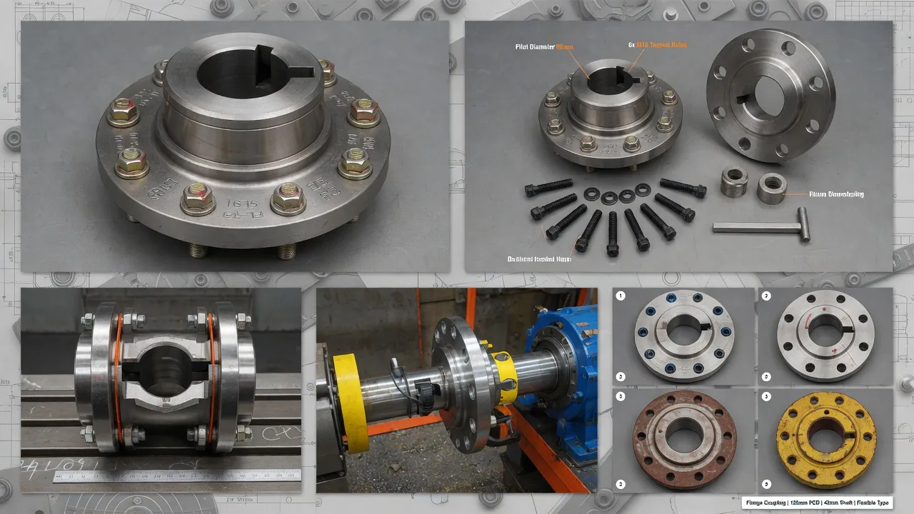
Why Sizing Matters More Than Most Engineers Realise
The most common coupling maintenance problem in Australian industry is not a product quality issue — it is a sizing error that was locked in at the time of purchase. An under-rated coupling fails from overload. An over-rated coupling may be too large for the available space, too heavy for the shaft overhang limit, or may have a torsional stiffness that creates resonance in a sensitive drivetrain. Both errors cost more to correct after installation than they would have to avoid with a five-minute sizing calculation upfront.
Step 1: Calculate the Nominal Running Torque
The starting point for every coupling sizing exercise is the nominal running torque at the shaft where the coupling will be installed.
Example: 55 kW motor running at 1,450 RPM → Tnominal = 9,550 × 55 ÷ 1,450 = 362 Nm
If the coupling is on the output shaft of a gearbox rather than directly on the motor shaft, multiply the motor torque by the gearbox ratio and divide by the gearbox efficiency: Toutput = Tmotor × i / η. A 362 Nm motor torque through a 10:1 ratio gearbox at 97% efficiency gives 362 × 10 / 0.97 = 3,732 Nm at the gearbox output — the coupling at the gearbox output must be sized for this figure, not the motor torque.
Step 2: Apply the Service Factor
The nominal torque is what the coupling transmits at steady rated speed. The design torque is what the coupling must be rated for — accounting for starting peaks, shock loads, and cyclic torque variation.
| Load Type | Examples | Service Factor | Notes |
|---|---|---|---|
| Smooth, continuous | Centrifugal pump, fan, blower | 1.25–1.50 | DOL starting adds 0.25–0.5 to factor |
| Moderate pulsation | Screw pump, agitator, mixer | 1.50–2.00 | Increase if start frequency > 10/hour |
| Heavy shock | Crusher, granulator, shredder | 2.50–3.00 | Verify at full load with peaked torque |
| Severe reciprocating load | Piston compressor, piston pump | 3.00–4.00 | Torsional analysis recommended |
Continuing the example: 362 Nm nominal torque × service factor 1.5 (centrifugal pump, DOL start) = 543 Nm design torque. The selected coupling must be rated for at least 543 Nm.
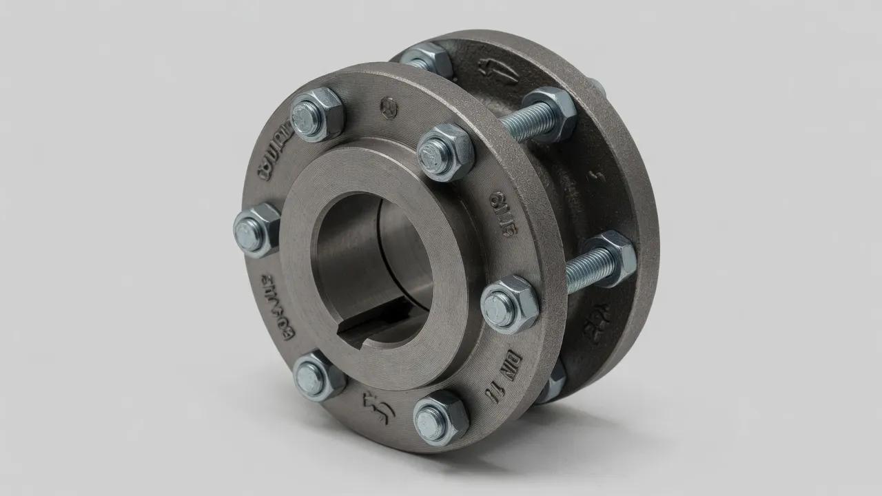
Step 3: Match the Bore Sizes to Both Shafts
Identify the motor shaft diameter and the driven machine shaft diameter. Both must fall within the bore range of the selected coupling size. If the motor and pump shafts are different diameters (common — a 55 kW motor may have a 55 mm shaft, the pump a 48 mm shaft), the coupling must have two separately machined hubs — one for each shaft size. Confirm the keyway dimensions for each shaft diameter per ISO 773 and verify that the keyway shear area at each bore size can transmit the design torque calculated in steps 1 and 2.
Step 4: Select Coupling Type for the Application
With the torque rating and bore sizes established, the coupling type is selected based on the application’s misalignment characteristics, maintenance requirements, and environmental conditions.
Rigid Coupling
Select when: shaft alignment is guaranteed under all operating conditions; zero torsional compliance is required; high precision torque transmission. Bore range 12–200 mm, torque to 35,000 Nm.
Flexible Tyre Coupling
Select when: misalignment is likely or inevitable; vibration damping is needed; maintenance team prefers simple element replacement. Bore range 12–160 mm, torque to 10,000 Nm.
Disc Coupling
Select when: zero backlash is required (servo, encoder); high-speed operation; maintenance-free operation needed. No elastomeric element; all-metallic.
Fluid Coupling
Select when: controlled soft start is required; large inertia loads; overload protection needed. Not a rigid coupling — power transmission through oil film.
Step 5: Check Speed, Environment, and Guard Clearance
The final checks before ordering are: verify the coupling’s maximum RPM rating exceeds the application speed (including any VSD overspeed); check that the elastomeric element material suits the operating temperature and chemical environment; and confirm the coupling’s outer diameter fits within the available guard clearance. A coupling that is correct in torque and bore but too large for the guard space or too fast for the RPM rating will still fail — these final checks prevent arriving at site with an unusable coupling.
Frequently Asked Questions
Need Expert Coupling Advice?
Our engineering team in Condell Park NSW is ready to help — free of charge.