
Fan drive coupling selection involves a specific set of considerations that distinguishes it from pump coupling selection in ways that are easy to underestimate. The higher rotational inertia of fan impellers, the vibration transmission consequences in occupied buildings, the UV exposure risk for outdoor equipment, and the potential energy savings from variable-speed fluid coupling designs all influence the coupling specification for fan drives in ways that a standard pump coupling selection guide does not fully address. This guide covers fan drive coupling selection from small HVAC fans to large industrial forced-draught (FD) and induced-draught (ID) fans, with guidance on when a flexible tyre coupling is the right answer and when a YOX series fluid coupling adds value beyond what a simpler coupling can provide.
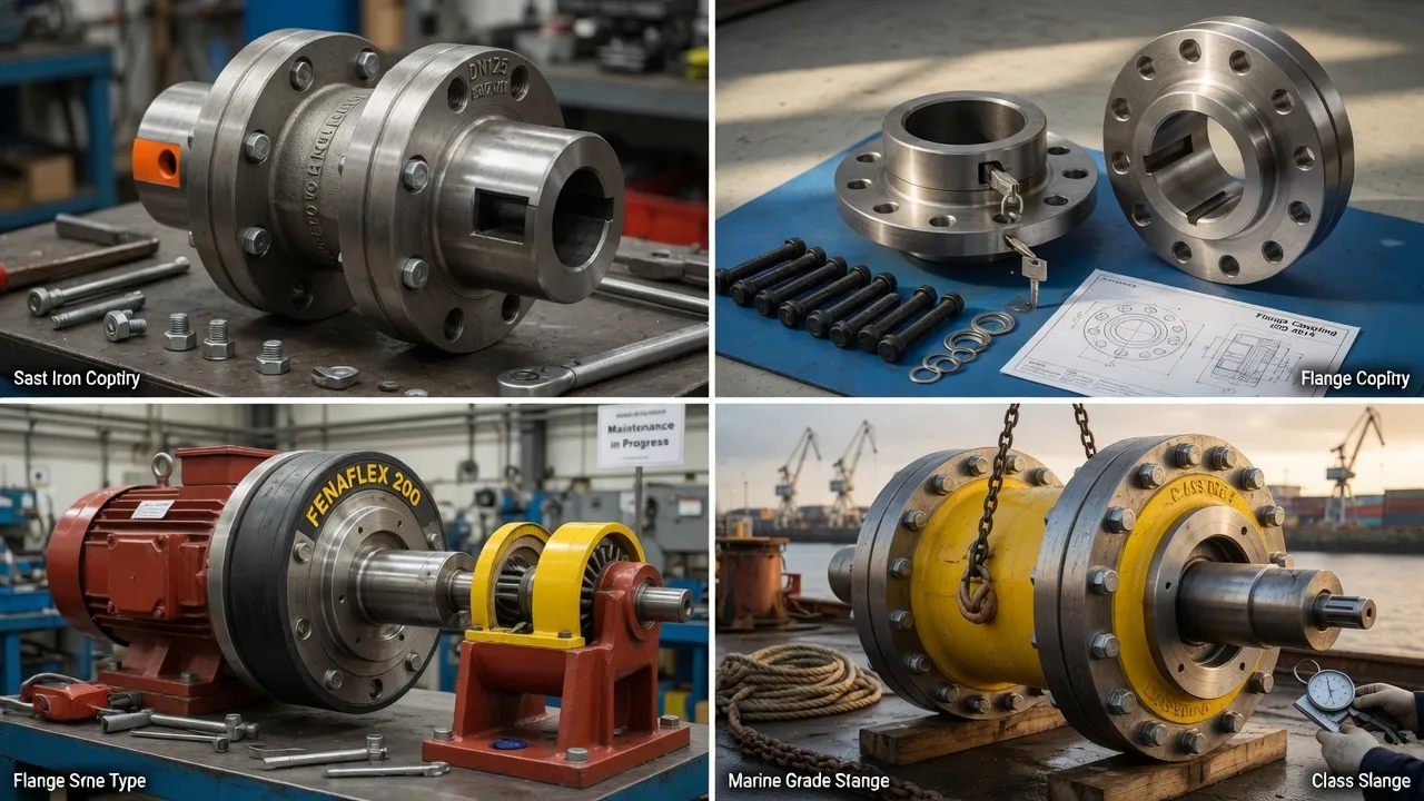
Why Fan Drives Are Different from Pump Drives
The mechanical behaviour of a fan drive differs from a pump drive in three important ways that affect coupling selection:
Higher rotational inertia: A centrifugal fan impeller is a large-diameter, relatively lightweight structure. Its moment of inertia (proportional to mass × radius²) is high relative to an equivalent pump impeller because the mass is distributed at large radius. Higher inertia means the motor must work harder and longer to accelerate the fan to operating speed, producing higher-peak starting torque and a longer acceleration period. Both factors increase the demand on the coupling during each start event.
Structure-borne vibration sensitivity: Fan drives in buildings are connected — through the fan structure, ductwork, and floor — to occupied spaces. Torsional vibration transmitted through a stiff coupling can excite the fan casing and ductwork into structural resonance, radiating noise and vibration into the building. A flexible coupling with an elastomeric element attenuates torsional vibration before it reaches the fan shaft and fan structure, reducing the building’s exposure to this vibration source.
Variable load character: Unlike a pump operating at a fixed system curve, a fan’s load varies with the air density, damper positions, and ductwork resistance. The coupling must handle the full range of load conditions from no-load run-up through peak load, plus any overload conditions from blocked filters or upstream resistance changes.
Fan Coupling Selection by Application
| Fan Application | Power Range | Starting Method | Recommended Coupling | Service Factor | Key Specification |
|---|---|---|---|---|---|
| Small HVAC AHU fan | 0.37–7.5 kW | DOL or VSD | F60–F100 flexible tyre coupling | 1.50–1.75 | Vibration damping for occupied building |
| Medium HVAC fan (belt drive) | 5.5–30 kW | DOL or VSD | F100–F125 flexible tyre coupling | 1.75–2.00 | Belt tension adds to bearing radial load — flexible coupling reduces additional load from misalignment |
| Large HVAC / commercial fan | 22–90 kW | DOL or soft-start | F160–F200 flexible tyre coupling | 2.00–2.25 | High inertia — verify starting torque peak against coupling rating |
| Industrial centrifugal fan (process) | 30–500 kW | DOL or fluid coupling | F160–F250 or fluid coupling + flange | 2.00–2.50 | Fluid coupling for smooth start on high-inertia fan |
| ID / FD fan on boiler or furnace | 100–2,000 kW | Fluid coupling | YOX fluid coupling + heavy flange | N/A (fluid coupling controls start) | Fluid coupling provides speed control and overload protection |
| Ventilation fan (outdoor, industrial) | 1.1–30 kW | DOL or VSD | F80–F160, EPDM element | 1.75–2.25 | EPDM for UV resistance in outdoor installation |
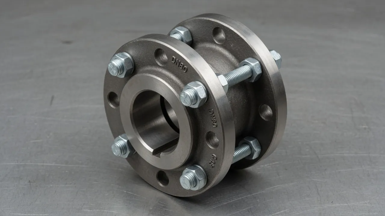
Vibration Isolation for HVAC Fan Drives — Getting It Right
In commercial buildings, the acceptable vibration velocity at occupied floors adjacent to plant rooms is typically 1–3 mm/s RMS for continuous operation (to AS 2625 and ASHRAE standards). A motor-fan drive without a flexible coupling can produce 8–15 mm/s at the motor bearing housing, with a significant fraction of this transmitted through the fan shaft and structure to the building. An F-type flexible tyre coupling with an 80A Shore element reduces the motor-to-fan torsional vibration transmission by 50–70%, contributing meaningfully to compliance with building vibration criteria.
Anti-vibration mounts under the motor and fan should also be specified in isolation-critical applications — the flexible coupling addresses torsional vibration through the shaft path; the anti-vibration mounts address lateral and vertical vibration through the structural path. Both are needed for comprehensive vibration isolation in occupied buildings.
Frequently Asked Questions
Need Expert Coupling Advice?
Our engineering team in Condell Park NSW is ready to help — free of charge.