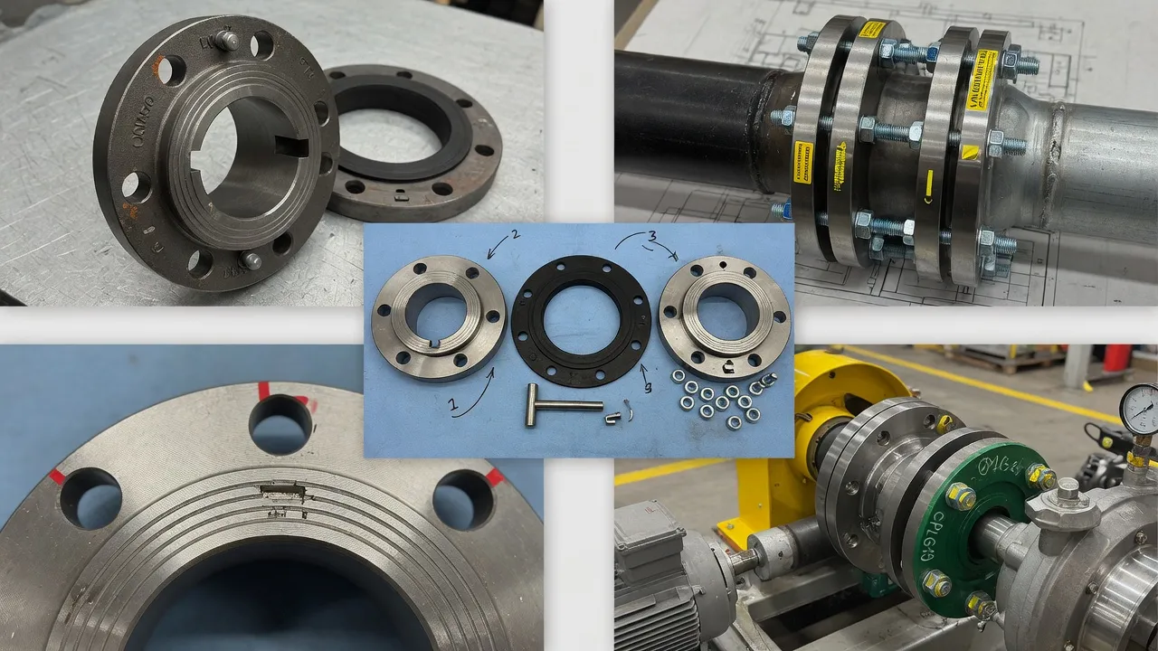
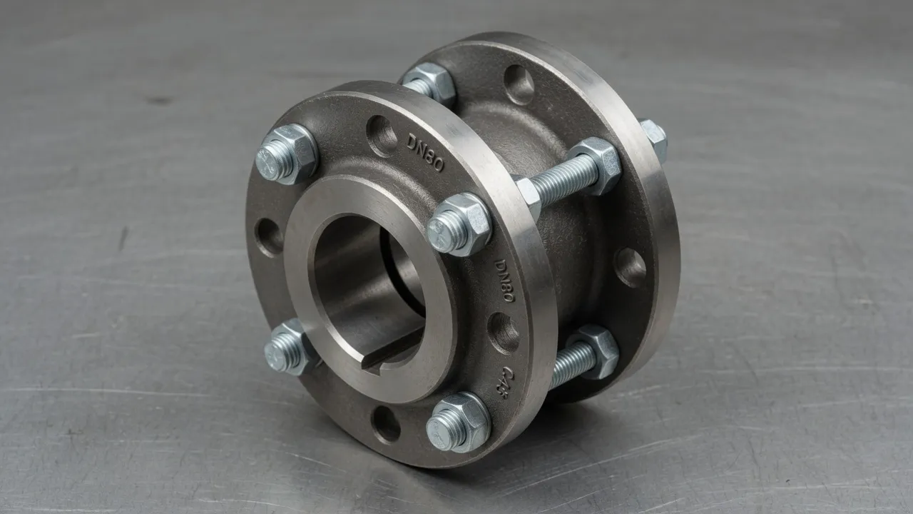
Installing a flange coupling correctly is one of those tasks that looks straightforward on paper but carries a long list of details that, if missed, translate directly into shortened service life, increased bearing failures, and mechanical seal problems. At Ever Power Flange Couplings Australia, our Condell Park engineering team handles warranty cases where coupling failures traced not to product defects but to installation errors that are entirely preventable with the right procedure.
Tools and Materials You Need Before Starting
Torque Wrench
Calibrated, covering the bolt torque range for your coupling bolt size — typically 40–250 Nm for most pump couplings.
Dial Indicator + Magnetic Base
For checking hub runout and coupling face runout after fitting. 0.001 mm resolution minimum.
Laser Alignment System
The current standard for shaft alignment. Dial indicator alignment is acceptable but slower and less reliable.
Keyway File and Soft Mallet
For hub fitting and deburring before assembly.
Anti-Seize Compound
Applied to bolt threads before tightening to prevent galling and allow removal.
️
Infrared Thermometer
For monitoring hub temperature if heat fitting is required.
Inspect and Clean All ComponentsBefore anything goes onto the shaft, inspect both hubs for bore finish, keyway condition, and any casting or machining defects. Clean all shaft ODs, hub bores, and keyways with a clean rag and solvent. Any burr not removed now will score the hub bore during fitting and create a stress concentration that promotes fretting fatigue.
2
Check Hub Bore and Shaft Diameter FitMeasure the shaft OD and hub bore ID with a micrometer. Verify the fit class matches the coupling datasheet specification — typically H7 bore over k6 or n6 shaft for a light interference or transition fit. If the hub is too tight to push on by hand for a clearance-fit design, do not force it — check measurements against the drawing.
3
Fit the Key to the Shaft and Hub KeywayThe parallel key should be a snug push-fit in the shaft keyway and a close clearance fit in the hub keyway. The key should seat fully in the shaft keyway with no rocking. File any burrs and verify the key stands the correct height above the shaft OD before fitting the hub.
4
Fit the Hub to the ShaftFor clearance or transition fits: push or lightly tap the hub onto the shaft using a soft-faced mallet, with force applied through a brass drift bearing on the hub face — never strike the hub flange directly. For interference fits: heat the hub uniformly to 100–150°C in an oven, then slide it onto the shaft quickly. Check axial position against the drawing dimension before it sets.
5
Check Hub RunoutMount a dial indicator on a magnetic base fixed to the motor frame. Check radial runout on the hub OD — within 0.05 mm TIR for standard applications, 0.02 mm for high-speed drives. Check face runout on the flange face — also within 0.05 mm TIR.
6
Check for Soft-FootPlace the motor on the baseplate with all hold-down bolts finger-tight. Check for soft-foot using feeler gauges between each motor foot and the baseplate. Any foot showing more than 0.05 mm gap must be shimmed before alignment begins.
7
Perform Laser Shaft AlignmentMount the laser alignment heads on each hub and run the alignment routine. Target: angular within 0.05° and parallel within 0.05 mm for rigid couplings; within 0.1° and 0.1 mm for flexible types. Record the final readings.
8
Assemble the Elastomeric Element (Flexible Couplings)Position the elastomeric tyre between the two hub flanges before bringing the flanges together. The tyre should fit freely with no residual stretch or compression. Check that the axial gap between hub faces matches the DBSE on the coupling drawing.
9
Fit and Torque the Coupling BoltsInsert all coupling bolts with anti-seize compound on threads and tighten finger-tight. Then torque in a cross-pattern — never tighten bolts sequentially around the circle. Perform two full cross-pattern torque passes to the specified value. Re-check alignment after final bolt tightening.
10
Fit the Coupling Guard and Record Installation DataNever commission a coupled machine without a coupling guard fitted. Record the final alignment readings, torque values, and shimming data in the equipment file — this baseline is essential for future troubleshooting.
Soft mallet on brass drift, or oven heating for interference fits
Skipping soft-foot correction
Unreliable alignment — shaft shifts as bolts are tightened
Shim all feet to within 0.05 mm before alignment
Tightening coupling bolts sequentially
Uneven flange face loading, fretting on mating faces
Cross-pattern tightening in two passes
Not checking runout after hub fitting
Misalignment built into the hub itself is undetectable
Dial indicator check — radial and face runout before proceeding
Commissioning without a coupling guard
Safety hazard; UV degrades elastomeric elements outdoors
Always fit guard before first start-up
Frequently Asked Questions
Do I need to heat the hub before fitting it to the motor shaft?+
Heating is required only when the hub-to-shaft fit is specified as an interference fit. For transition or clearance fits with a keyway, the hub can normally be pushed on by hand or with light mallet pressure after cleaning. Never use a direct flame — use an oven or induction heater to maintain even temperature and prevent localised thermal stress.
What torque should I use when tightening coupling bolts?+
Refer to the coupling manufacturer’s datasheet. As a general guide, M10 Grade 8.8 bolts are typically torqued to 47–50 Nm, M12 to 80–85 Nm, and M16 to 195–210 Nm. Always use a calibrated torque wrench and tighten in a cross-pattern to ensure even flange face loading.
How accurately do I need to align a flange coupling?+
For rigid flange couplings, alignment within 0.05 mm TIR is required. For flexible flange couplings with a tyre element, alignment should be set to within 0.1 mm parallel and 0.1° angular at commissioning to maximise elastomeric element service life and protect bearings from unnecessary radial loads.
Can I reuse coupling bolts after removal?+
Grade 8.8 coupling bolts can generally be reused if they show no visible stretching, thread damage, or corrosion. Grade 10.9 bolts should be replaced after removal. Always clean bolt threads and apply a light coating of anti-seize compound before refitting.
What is soft-foot and why does it matter for coupling installation?+
Soft-foot refers to a condition where one or more motor feet do not sit flat on the baseplate, causing the motor frame to distort when hold-down bolts are tightened. This shifts the shaft position and misaligns the coupling. Correct soft-foot before final alignment by shimming the affected foot to within 0.05 mm.
Need Expert Coupling Advice?
Our engineering team in Condell Park NSW is ready to help — free of charge.