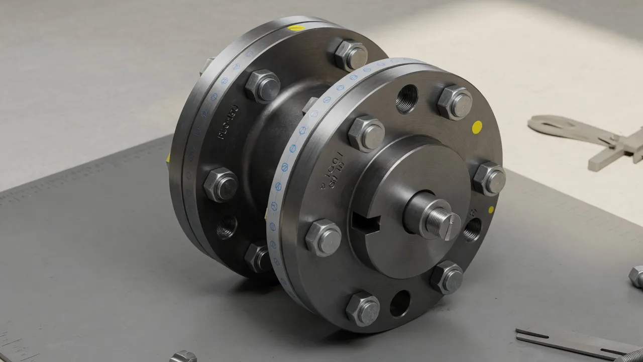
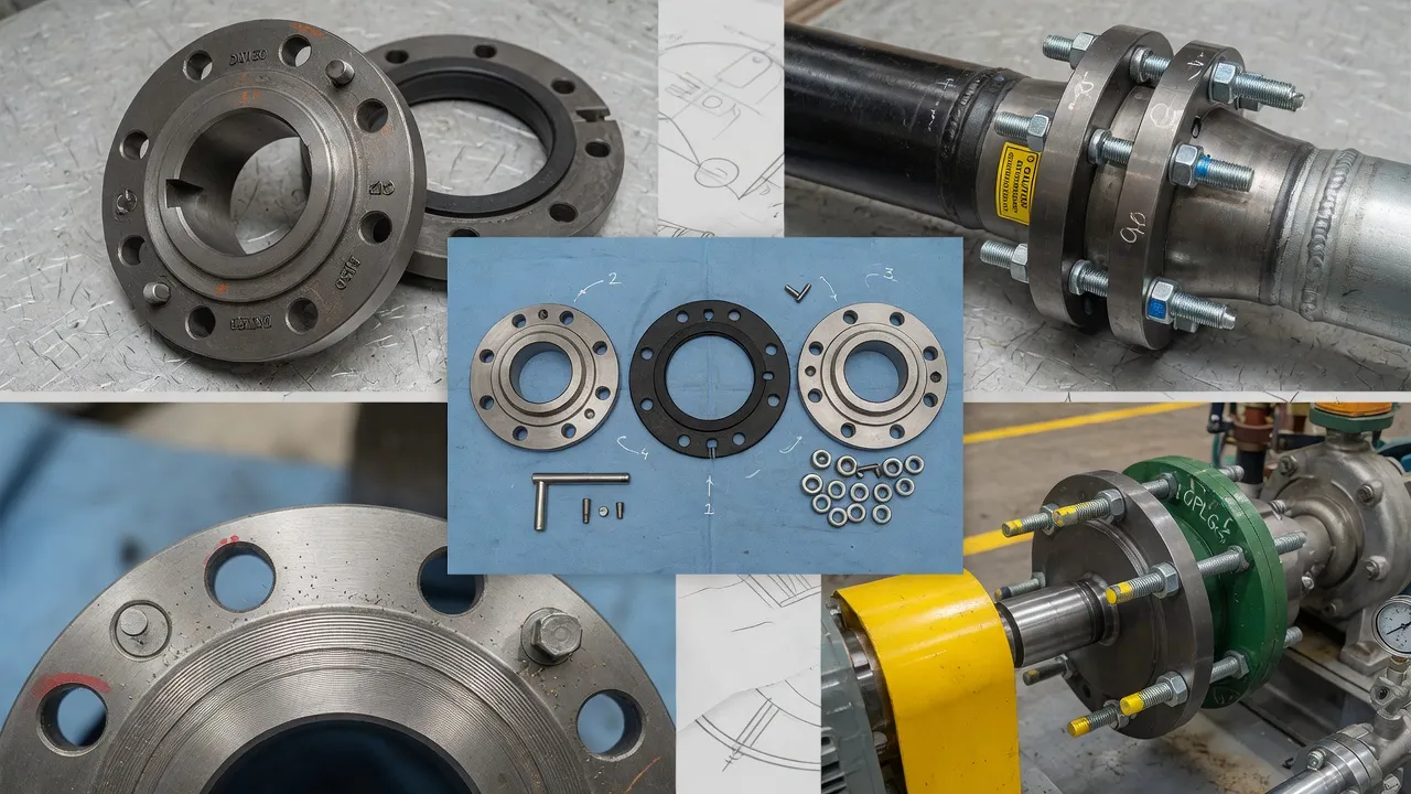
Coupling inspection is one of the most neglected maintenance activities in Australian industrial plant — not because engineers do not know it matters, but because coupling guards make the coupling invisible during normal operation, and the symptom of a deteriorating coupling (increasing vibration) is easy to attribute to other causes. By the time a coupling fails visibly, the bearing damage it has caused is already done. This guide provides a structured, practical inspection procedure for the two most common coupling types encountered in industrial maintenance — the flexible F-type tyre coupling and the rigid cast iron and steel flange coupling — and establishes clear criteria for when replacement is warranted.
Audible knock during deceleration, guard rattling, coupling temperature
Inspecting a Flexible Tyre Coupling (F-Type)
1
Remove the Coupling GuardEnsure the machine is isolated (LOTO). Remove the coupling guard completely — do not attempt to inspect through a guard inspection port, as only a fraction of the tyre surface is visible. The guard often contains rubber debris that is itself diagnostic evidence.
2
Examine the Rubber Debris in the GuardIf rubber dust, crumbled pieces, or chunks of elastomeric material are present inside the guard, the tyre element has experienced accelerated wear. The amount and character of the debris indicates severity — dust alone suggests early-moderate wear; visible chunks indicate advanced or end-stage wear.
3
Inspect the Tyre Element — All SurfacesRotate the coupling by hand through one full revolution while observing the tyre element from as many angles as possible. Look for: circumferential cracking across the tyre profile, axial cracking along the tyre flanks, chunking or missing sections, oil contamination (swelling and softening), UV-induced surface hardening (crazing), and any deformation that suggests the tyre has shifted on the hub flanges.
4
Check Hub Flange and Tyre Seat ConditionInspect the hub flange faces where the tyre seats. Any fretting marks, step-worn edges, or corrosion at the tyre-flange interface indicates the tyre has been slipping on the hub — a sign of torque overload or incorrect tyre retention. The tyre retention bolts (if fitted) should be checked for correct torque.
Inspecting a Rigid Flange Coupling
1
Check Flange Face ConditionInspect the mating flange faces for fretting — a reddish-brown oxide ring at the contact diameter indicates bolt preload has been insufficient to prevent micro-slip. Any fretting at the flange face means the bolt torque has been inadequate and the coupling has been transmitting torque partly through flange friction — which will produce progressive wear and eventual bolt shear if not corrected.
2
Inspect the Hub Bore and KeywayIf the hub can be removed (during a pump or motor overhaul), inspect the hub bore for fretting corrosion, scoring, or bell-mouthing at the hub face. Check the keyway for peening, cracking at the keyway corners, and key contact pattern. The key should show uniform contact across its full bearing length — concentrated contact at one end indicates bending load on the key from angular misalignment.
3
Check Coupling Bolts and Bolt HolesInspect all coupling bolts for corrosion, thread condition, and any visible stretching. Check bolt holes in both flange faces for elongation in the direction of rotation — elongated bolt holes indicate the coupling has been transmitting torque through bolt shear rather than flange friction, which is a sign of under-torqued bolts.
4
Crack Inspection at Hub Root RadiusThe highest stress concentration in a rigid flange coupling hub is at the root radius — the transition between the hub barrel and the flange face. Inspect this radius for surface cracks using a dye penetrant test if any doubt exists. A crack found at this location is grounds for immediate hub replacement.
Replacement Decision: Replace the Element or the Whole Coupling?
Finding
Recommended Action
Tyre element: surface cracking only, no chunks, no debris
Continue service — schedule replacement at next shutdown
Tyre element: chunking, rubber debris in guard
Replace tyre element immediately — do not defer
Hub jaws: smooth, no scoring or deformation
Reuse hub — replace tyre element only
Hub jaws: scoring, peening, or deformation from metal contact
Replace both hubs and tyre element — new tyre on damaged jaws fails rapidly
Rigid coupling hub: cracked
Immediate replacement — do not continue service
Rigid coupling hub: fretting at bore, key peening
Replace hub and key — inspect shaft keyway before refitting
Coupling bolts: elongated holes, bolt stretching
Replace bolts and inspect hub flange faces for wear
Frequently Asked Questions
How do I inspect a flange coupling without removing it from the shaft?+
With the machine stopped and isolated, remove the coupling guard and perform a visual inspection of the accessible surfaces. For flexible tyre couplings, inspect the exposed tyre element faces for cracking, oil contamination, or deformation. Rotate the coupling by hand and feel for any rotational resistance variation that would indicate a damaged or seized elastomeric element. Check for rubber dust or debris inside the guard cavity. For rigid couplings, inspect the bolt heads and exposed flange faces for corrosion, fretting marks, and any cracking at the hub root radius.
What does fretting corrosion look like on a coupling hub?+
Fretting corrosion on a coupling hub bore presents as a reddish-brown powder (iron oxide) at the bore-to-shaft interface, visible at the hub face where the shaft enters the hub. It indicates micro-slip between the hub bore and the shaft OD — a sign that the hub-to-shaft fit is too loose for the torque being transmitted, or that the keyway is overloaded. On the flange face, fretting between mating flanges appears as a circular ring of reddish powder at the contact diameter, indicating bolt preload is insufficient to prevent micro-slip under torque.
Can I replace just one hub of a flange coupling, or do I need to replace both?+
If only one hub shows damage — cracked bore, worn keyway, or deformed flange face — that hub can be replaced individually provided the replacement hub matches the original’s flange dimensions, bolt circle, and bore specification. Mismatched hub flanges (different PCD, bolt hole size, or flange face OD) will produce uneven bolt loading and a false register between hubs. If both hubs are from the same manufacturer and size, replacing one is straightforward. If the origin of the original hubs is unknown, replace both to ensure dimensional match.
How do I know if coupling bolts need replacing?+
Coupling bolts should be replaced if any of the following are observed: visible stretching (the thread pitch appears uneven under magnification), corrosion pitting that reduces the effective cross-section, any cracks at the bolt head fillet radius, elongated bolt holes in the flange (indicating the bolt has been loaded in shear beyond yield), or a bolt that will not achieve the specified tightening torque (indicating the threads have yielded). Grade 10.9 bolts that have been torqued to yield must always be replaced — they cannot be reused.
How often should coupling alignment be checked as part of inspection?+
Laser alignment should be checked annually for all coupled machines operating above 15 kW, and at every planned maintenance shutdown regardless of interval. Additionally, check alignment immediately after any motor or pump replacement, after any significant vibration event or coupling failure, after concrete grouting of baseplates (which settles for up to 6 months), and whenever bearing temperature rises unexpectedly without a clear alternative explanation.
Need Expert Coupling Advice?
Our engineering team in Condell Park NSW is ready to help — free of charge.