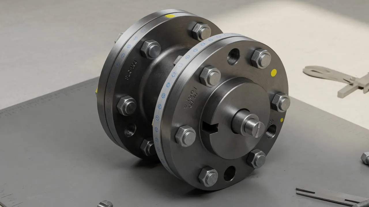
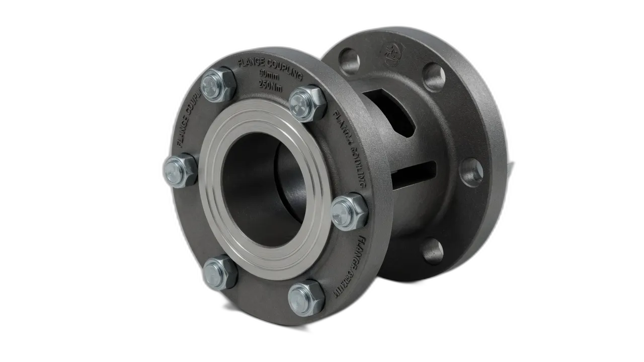
The keyway is the most common coupling hub-to-shaft connection method in Australian industrial machinery, yet it is one of the least understood from an engineering perspective. Most maintenance teams know that “the key goes in the slot” — but the specific dimensions that determine whether the connection is correct, the stress concentrations that make keyways the most common hub failure initiation site, and the installation details that prevent fretting and slip are frequently overlooked. This guide covers the engineering of keyway connections for EP-YL rigid coupling and cast iron and steel shaft coupling hubs — the dimensions that matter, the fits that work, and the installation practices that determine whether a keyed coupling hub lasts for decades or fails within months.
What a Keyway Does — and Why Getting It Right Matters
A keyway connection transmits torque from the shaft to the coupling hub through a steel key fitted into matching keyways machined in both the shaft OD and the hub bore. The key transmits torque through compressive bearing stress on its side faces — the key is pushed against the hub keyway wall on one side under torque, and the opposite face bears against the shaft keyway wall. This bearing contact transmits torque through the key cross-section.
The keyway is also the single most common location for coupling hub fatigue crack initiation. The sharp corners at the keyway root create a stress concentration factor of 1.5–3.0 depending on the corner radius — under cyclic torque, the maximum stress at the keyway root corners significantly exceeds the nominal bore stress. If the cyclic stress at the root exceeds the material’s fatigue limit, cracks initiate at the corners and propagate outward under continued loading. This is why correct keyway geometry — specifically the root radius — is as important as correct key dimensions.
ISO 773 Keyway Dimensions — The Australian Standard
Shaft Diameter (mm)
Key Width × Height (mm)
Shaft Keyway Depth (mm)
Hub Keyway Depth (mm)
Min. Root Radius (mm)
6–8
2 × 2
1.2
1.0
0.16
8–10
3 × 3
1.8
1.4
0.16
10–12
4 × 4
2.5
1.8
0.25
12–17
5 × 5
3.0
2.3
0.25
17–22
6 × 6
3.5
2.8
0.25
22–30
8 × 7
4.0
3.3
0.4
30–38
10 × 8
5.0
3.3
0.4
38–44
12 × 8
5.0
3.3
0.4
44–50
14 × 9
5.5
3.8
0.4
50–58
16 × 10
6.0
4.3
0.4
58–65
18 × 11
7.0
4.4
0.6
65–75
20 × 12
7.5
4.9
0.6
75–85
22 × 14
9.0
5.4
0.6
85–95
25 × 14
9.0
5.4
0.6
95–110
28 × 16
10.0
6.4
0.6
The Key Fit — Getting the Tolerance Right
The fit of the key in the keyway determines whether the connection transmits torque by key side-face bearing (correct) or by key bottom bearing (incorrect). The correct fit has:
Key in shaft keyway: A tight sliding fit — the key should push in by hand without significant force but must not rock side-to-side. The key bottom should make full contact with the keyway floor. No perceptible play in the width direction.
Key in hub keyway: A clearance fit — the key should slide into the hub keyway with minimal force. The hub keyway depth is designed so there is a small gap between the key top and the hub keyway ceiling. This gap is critical — if the key contacts the ceiling before the hub is fully seated, the key will act as a wedge and split the hub bore.
Critical Installation Steps for Keyed Coupling Hubs
1
Check Key and Keyway DimensionsBefore assembly, measure the key width and the shaft keyway width with a micrometer. The key width should be within the specified tolerance for a tight sliding fit in the shaft keyway (typically H9/n9 or H9/js9 fit). Check keyway depth against ISO 773 — a keyway that is too shallow will not develop full torque capacity; one that is too deep may weaken the shaft cross-section.
2
Deburr All EdgesUse a fine file or deburring tool to remove all machining burrs from keyway edges — both the shaft keyway and the hub keyway. A burr at the keyway entry can score the hub bore as it is pushed onto the shaft, creating a stress concentration at the score mark.
3
Apply Anti-Seize to Key Side FacesApply a thin film of copper-based anti-seize to the key side faces and to the shaft OD in the keyway region. This prevents fretting at the key-to-keyway interface and ensures the key can be removed cleanly at future maintenance.
4
Seat the Key Fully in the Shaft KeywayPush or tap the key fully into the shaft keyway using a soft mallet. The key bottom must contact the keyway floor — there must be no gap under the key. An unseated key applies point loads to the hub bore instead of distributed face loads, dramatically increasing hub bore stress.
5
Check Key Height Above Shaft ODWith the key seated, measure the key height above the shaft OD surface. This should match the hub keyway depth specification from ISO 773 — if the key stands too high, it will contact the hub keyway ceiling before the hub bore is fully seated on the shaft, acting as a wedge.
Frequently Asked Questions
What is the standard keyway size for a 50 mm shaft?+
Per ISO 773 (adopted in Australia), a 50 mm shaft uses a 14 mm × 9 mm parallel key (width × height). The keyway in the shaft is 14 mm wide and 5.5 mm deep (half the key height plus half the key depth allowance). The keyway in the hub bore is 14 mm wide and 3.8 mm deep. These dimensions are standardised — any coupling hub specified for 50 mm bore to ISO 773 will have this keyway, and any key to ISO 773 at 14×9 will fit correctly. Always specify keyway dimensions to ISO 773 when ordering coupling hubs to ensure interchangeability.
Can I use a keyway in a coupling hub on a stainless steel shaft?+
Yes. Stainless steel shafts can have keyways machined into them using the same tooling and procedures as carbon steel. The key material should also be stainless steel (316L is appropriate for most applications) to prevent galvanic corrosion at the key-keyway interface in wet or corrosive environments. On 316 stainless shafts, the key sliding fit should be checked carefully — 316 stainless work-hardens and the keyway surface can seize with a stainless key if the fit is too tight. Apply a light film of copper-based anti-seize to the key before installation on stainless assemblies.
What is a Woodruff key and when is it used instead of a parallel key?+
A Woodruff key is a semicircular (half-moon) shaped key that fits into a curved seat cut in the shaft and a straight slot in the hub. It is used primarily on tapered shaft ends — it self-aligns in the tapered seat without the need for key depth adjustment. Woodruff keys are common on smaller motor shaft ends (below 25 mm bore) and on tapered coupling bore designs. For the majority of industrial coupling applications with parallel (cylindrical) shafts, a parallel key per ISO 773 is used. Specify the key type (parallel or Woodruff) when ordering a coupling hub to ensure the correct keyway is machined.
How does keyway depth affect the coupling hub’s torque capacity?+
The keyway depth on the shaft determines the area of the key bearing face — the face that transmits torque from the key to the hub keyway wall. A deeper keyway provides more bearing area and higher torque capacity up to the limit imposed by the key width. The ISO 773 depth dimensions are calculated to provide a torque capacity that matches the shaft’s torsional capacity at that diameter — meaning a correctly specified ISO 773 keyway at the standard depth will not be the weakest link in the torque path. Reducing keyway depth below ISO 773 (through machining error or shallow keyway cutter) reduces torque capacity below the shaft’s full capacity.
What is fretting corrosion at a keyway and how do I prevent it?+
Fretting corrosion at a keyway occurs when micro-slip between the key side faces and the keyway walls generates fine iron oxide powder under cyclic torque loading. This can happen when the key width is slightly loose in the keyway, when the key bottom does not fully contact the keyway floor (leaving a void), or when torque reversals cause cyclic relative movement between key and keyway. Prevention: ensure the key is a snug fit in the shaft keyway (no perceptible side play); apply a thin film of anti-seize to key side faces before installation; and where reversing torque is present, consider using two keys at 180° to eliminate the clearance that allows reversal slip.
Need Expert Coupling Advice?
Our engineering team in Condell Park NSW is ready to help — free of charge.