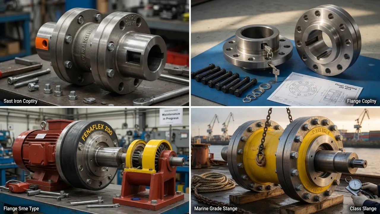
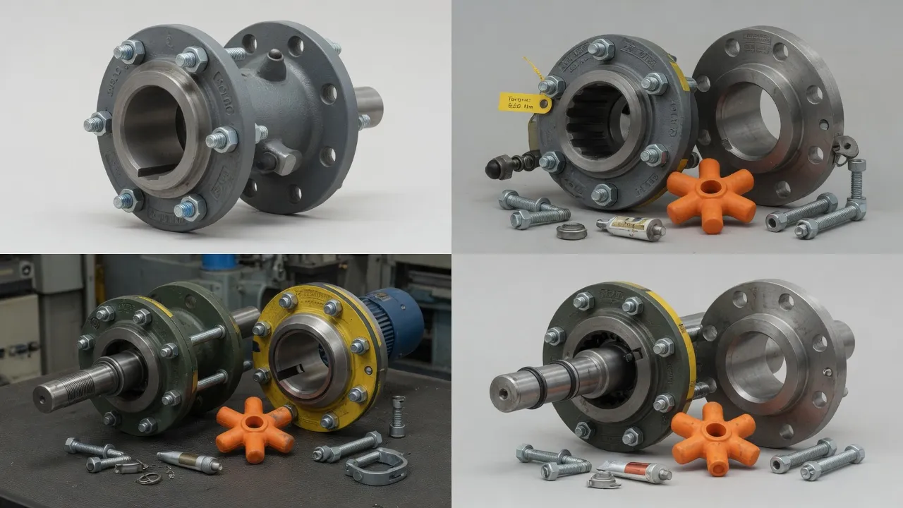
A pump drive that keeps breaking couplings is one of the most reliable indicators of an unresolved underlying problem in the drivetrain — more reliable than bearing failure rates, vibration readings, or seal replacement frequency. A coupling that fails repeatedly is not a defective product; it is a diagnostic instrument pointing at a root cause that has survived every attempt to fix the symptom. Finding and eliminating that root cause is the only way to break the cycle. This guide provides a systematic troubleshooting approach for the pump drive that has consumed multiple couplings, leading through the diagnostic steps from site observation to root cause identification and corrective action. The F-type flexible tyre coupling is the most common coupling type involved in repeat failures on Australian pump drives, with the spacer coupling design providing an important diagnostic and maintenance efficiency advantage once the root cause is identified.
The Diagnostic Framework: Three Questions Before Replacing Again
Before a replacement coupling is ordered for a drive that has already consumed two or more couplings, three questions must be answered with evidence — not assumptions:
Question 1: What did the failed coupling look like, and what does the wear pattern tell us?
Question 2: When was shaft alignment last checked with a laser system — not by eye, not by straight edge?
Question 3: Is the replacement coupling rated for the actual design torque, calculated as nominal torque × service factor?
If the answers are “I don’t know,” “at installation” (without annual re-check), and “same size as the original,” the root cause investigation has not been completed.
Step 1 — Read the Failed Coupling
The failed coupling element is the richest source of diagnostic information available. Examine it before it is discarded:
Wear Pattern
Probable Root Cause
Next Diagnostic Step
One or two lobes severely worn, others minor
Angular misalignment — coupling loaded unevenly
Laser alignment check — check for angular misalignment in the plane of the worn lobes
Wear concentrated at one side of the element circumference
Parallel misalignment — offset in one direction
Laser alignment check — measure parallel offset in both planes
Uniform wear across all lobes — evenly distributed
Calculate design torque; verify against coupling rating; check service factor
Element very hard/brittle, surface crazing
Thermal degradation — operating above elastomer’s temperature limit
Check coupling guard temperature; verify ambient temperature; upgrade to EPDM or Hytrel
Element swollen, soft, oily
Chemical contamination — oil or solvent exposure
Identify contamination source; upgrade to neoprene (CR) element
Element brittle, surface cracked/faded
UV degradation — outdoor installation without UV protection
Upgrade to EPDM element; verify coupling guard condition
Step 2 — Check Alignment With Evidence
1
Perform Laser Alignment Before Touching AnythingBefore removing the motor for coupling replacement, perform a laser shaft alignment measurement on the machine in its current condition. This baseline reading reveals the current misalignment — which may be the cause of the coupling failure that just occurred. Record the reading: it is the evidence for or against misalignment as the root cause.
2
Check Alignment HistoryReview the equipment file for all previous laser alignment readings. If no records exist (alignment has never been formally checked), misalignment has never been excluded as a root cause — even if it was ‘checked at installation’ without documentation. Absence of alignment records is itself a significant finding.
3
Check for Soft-Foot and Hold-Down Bolt TorqueLoose or incorrectly torqued hold-down bolts allow the motor to shift position under operating loads, producing misalignment that was not present at the static alignment check. Check all hold-down bolts for correct torque. Check for soft-foot by observing shaft movement as individual hold-down bolts are loosened.
Step 3 — Verify the Coupling Torque Rating
1
Calculate the Actual Design TorqueT_nominal = 9,550 × kW ÷ RPM. Multiply by the service factor for the application (1.5 for centrifugal pump DOL start as a minimum). This is the design torque that the coupling must be rated for.
2
Compare to the Current Coupling RatingLook up the rated torque of the current coupling in the manufacturer’s datasheet. If the design torque exceeds the rated torque, the coupling is under-rated — upgrade to the next size. If the design torque is within the rating, overload is not the primary cause.
3
Consider Recent Changes to the DriveHas the motor been upgraded to higher power? Has the pump been modified (larger impeller, different operating point)? Has the start frequency increased? Any of these changes increases the applied torque without automatically triggering a coupling upgrade, and each can convert a correctly rated coupling into an under-rated one.
Step 4 — The Corrective Action Checklist
Once the root cause is identified, apply the corrective actions before fitting the replacement coupling:
If root cause is MISALIGNMENT
Perform laser shaft alignment to within 0.1 mm parallel and 0.1° angular in both planes. Correct soft-foot. Re-torque all motor hold-down bolts. Perform post-commissioning alignment check after first 72 hours of operation to catch thermal growth effects. Implement annual alignment check programme.
If root cause is TORQUE OVERLOAD
Calculate the correct design torque with service factor. Select a replacement coupling rated at least 20% above the design torque. Verify the elastomeric element hardness is appropriate — a harder element (92A or 98A) provides more torque capacity at the same coupling size than the standard grade.
If root cause is ENVIRONMENTAL DEGRADATION
Upgrade the elastomeric element grade to match the actual environment: EPDM for UV or chemical exposure; neoprene for oil contamination; Hytrel for high-temperature operation. Inspect the coupling guard and repair or replace if it is not providing adequate environmental protection.
Frequently Asked Questions
Why does my pump coupling keep failing every few months?+
Repeated coupling failure within months of replacement almost always indicates an underlying condition that has not been identified and corrected. The three most likely root causes are: misalignment (either the initial alignment was incorrect, or alignment has drifted due to baseplate settlement or thermal growth); torque overload (the coupling is under-rated for the actual operating torque including starting peaks and service factor); or incorrect elastomeric element specification (the element grade is wrong for the operating temperature, chemical environment, or speed). A coupling replacement that does not investigate the root cause of the previous failure will produce the same outcome.
What is the most common reason a pump coupling fails prematurely in Australia?+
Based on field investigation data from Australian water utilities, process plants, and mining operations, shaft misalignment is the confirmed or probable root cause in more than 60% of premature flexible coupling failures. The pattern is consistently the same: coupling replaced, machine returned to service without alignment check, coupling fails within 12–18 months from the same elastomeric element fatigue pattern, repeat. Implementing annual laser alignment checks after every coupling replacement breaks this cycle in the majority of cases.
How do I know if the coupling is failing from misalignment or from torque overload?+
The wear pattern on the failed elastomeric element distinguishes the two causes. Misalignment failure: the element shows uneven wear — one or two lobes significantly more compressed or torn than the others, or an asymmetric wear pattern across the tyre face. This asymmetry reflects the non-uniform loading that angular or parallel misalignment imposes on the element. Torque overload failure: the element shows uniform wear across all lobes, with fatigue cracking distributed evenly around the element circumference — all lobes experiencing the same overload cycle.
Should I upgrade coupling size if the coupling keeps failing?+
Upgrading coupling size — specifying a larger coupling with a higher torque rating — is the correct response when the root cause investigation concludes that the current coupling is under-rated for the actual operating torque. Calculate the design torque: T = 9,550 × kW ÷ RPM × service factor. If the current coupling’s rated torque is below this design torque, upgrade to the next size that exceeds it. However, if the root cause is misalignment rather than overload, upgrading coupling size will not solve the problem — a larger coupling will fail for the same reason as the smaller one if alignment is not corrected.
What should I check before fitting a replacement coupling on a pump that has had repeated failures?+
Before fitting a replacement, complete the following investigation: perform laser shaft alignment and record the readings; check all motor hold-down bolts for correct torque and soft-foot; inspect the failed coupling element wear pattern to determine whether failure was from misalignment (asymmetric wear) or overload (uniform wear); verify that the replacement coupling’s rated torque exceeds the design torque (nominal × service factor); confirm that the elastomeric element grade is appropriate for the operating environment; and check the baseplate condition for any cracking, grout deterioration, or settling that could cause alignment drift.
Need Expert Coupling Advice?
Our engineering team in Condell Park NSW is ready to help — free of charge.