
Servo motor coupling selection is governed by requirements that rarely appear in general industrial coupling specifications: zero backlash, high torsional stiffness, low inertia, and compatibility with the servo control loop dynamics. A coupling that is perfectly adequate for a pump drive — providing smooth torque transmission and vibration damping — can cause positioning error, control loop instability, or resonance on a servo axis if it introduces torsional compliance or backlash into the feedback loop. This guide explains what servo motor drives actually require from a coupling, and why the disc coupling and the flexible beam coupling are the two designs that most consistently meet those requirements.
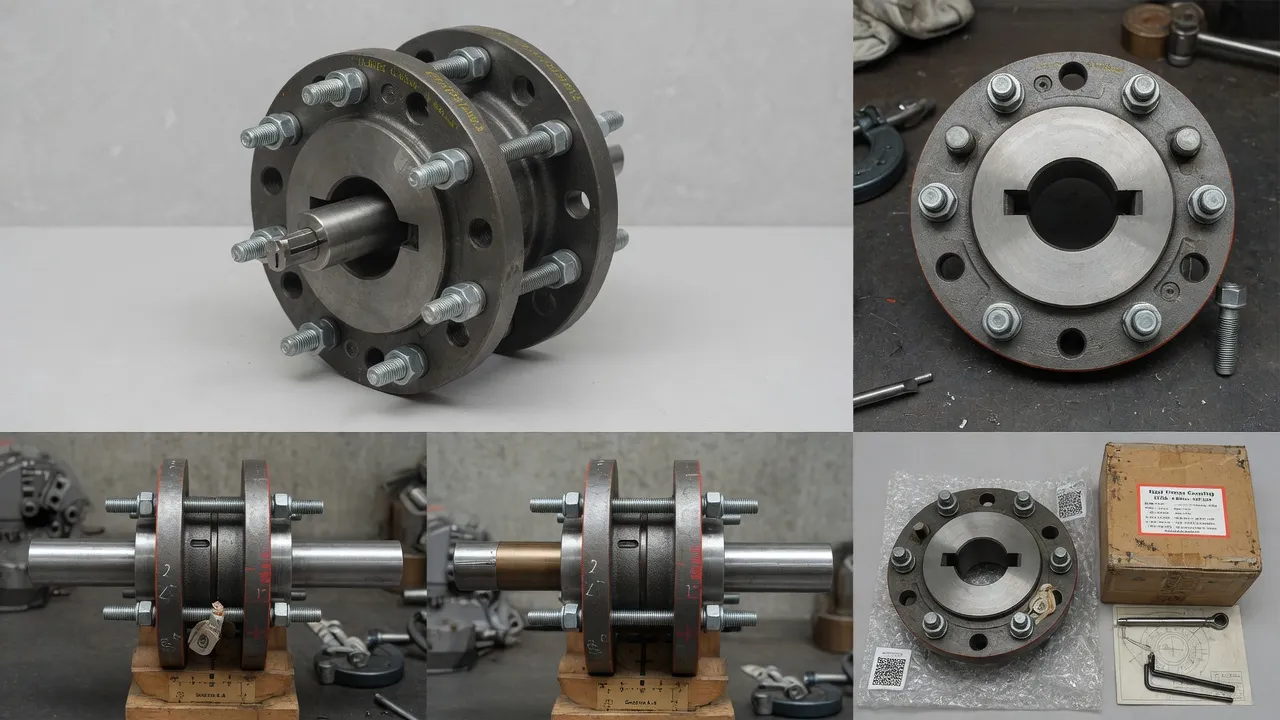
What a Servo Motor Coupling Must Deliver — and Why It Is Different
A standard industrial coupling is selected to transmit torque, accommodate misalignment, and damp vibration. A servo motor coupling must do all of these things and simultaneously provide zero backlash across the full torque range, torsional stiffness high enough that the coupling does not introduce a resonant mode within the servo bandwidth, and rotational inertia low enough that the load-to-motor inertia ratio stays within the servo amplifier’s stability specification.
The torsional stiffness requirement is the one that most engineers underestimate. A servo control system uses position feedback at the motor encoder — it does not directly measure position at the load. If the coupling between the motor and load has low torsional stiffness, the load can oscillate relative to the motor at the coupling’s torsional natural frequency while the motor encoder shows the motor shaft is stationary. This oscillation can excite the servo control loop into instability — causing vibration, positioning error, and mechanical noise that looks like a servo tuning problem but is actually a coupling stiffness deficiency.
Servo Coupling Selection Criteria
| Parameter | Why It Matters | Target Value (Servo Applications) |
|---|---|---|
| Backlash | Dead band in position feedback loop causes positioning error and possible loop instability | Zero — disc, beam, or bellows type only |
| Torsional Stiffness (kt) | Low stiffness → low torsional resonant frequency → risk of resonance in servo bandwidth | 3–5× servo bandwidth as minimum torsional natural frequency |
| Rotational Inertia | High coupling inertia raises load-to-motor inertia ratio, reducing servo response speed | Minimise — aluminium or small-diameter designs |
| Torque Rating | Must exceed peak motor torque during acceleration/deceleration, not just running torque | Coupling rated torque ≥ motor peak torque × 1.5 |
| Misalignment Tolerance | Servo axes often have very small misalignment — but compensation is still needed for thermal growth | 0.5°–1.0° angular; 0.05–0.15 mm parallel |
| Max Speed | Servo motors often run at 3,000–6,000 RPM — balance grade matters | Specified to ISO 1940 G2.5 or better above 3,000 RPM |
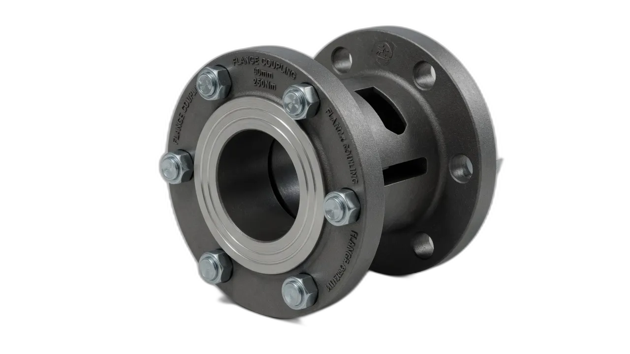
Disc Coupling vs Beam Coupling for Servo Applications
Both the disc coupling and the beam coupling provide zero backlash and high torsional stiffness. The choice between them is primarily determined by torque level and bore size.
Disc Coupling — Servo Grade
Zero backlash, highest torsional stiffness per unit size, torque range 1 Nm to 35,000 Nm. Available in aluminium, steel, or stainless. Accommodates misalignment at both angular and parallel planes simultaneously. The standard choice for servo drives above 65 Nm.
Flexible Beam Coupling
One-piece machined aluminium or stainless. Zero backlash, very low inertia, bore range 3–45 mm. Best for encoder connections, stepper motors, and light servo drives up to ~65 Nm. Cannot handle high misalignment — ideal for precision linear rail-guided axes.
Bellows Coupling
Metallic bellows provides zero backlash with highest misalignment tolerance of the three types. Lower torsional stiffness than disc type — more suitable where misalignment is harder to control. Used in medical devices, optical equipment, and light-load servo axes.
Inertia Matching — Why Coupling Inertia Matters for Servo Response
Servo amplifier manufacturers specify a maximum load-to-motor inertia ratio — typically 3:1 to 10:1 for standard servo systems. Exceeding this ratio reduces servo responsiveness and can make stable tuning impossible. The coupling’s rotational inertia contributes to the load inertia figure. For small servo motors (below 1 kW) with low-inertia loads, the coupling’s own inertia can represent 10–20% of the total load inertia — making the difference between an in-ratio and out-of-ratio system. Always add coupling inertia to the load inertia calculation when verifying the servo inertia ratio.
Frequently Asked Questions
Need Expert Coupling Advice?
Our engineering team in Condell Park NSW is ready to help — free of charge.