Description
The disc coupling — also known as a laminar disc pack flexible coupling — transmits torque through a pack of thin stainless steel discs bolted alternately to the drive and driven flanges around a common bolt circle. Pure elastic deflection of the disc pack handles angular and axial shaft misalignment with zero backlash in both rotational directions. No elastomeric element to degrade with age. No lubrication. No spline clearance. Precision balance carries the assembly past 20,000 rpm in turbomachinery configurations. The disc coupling is the engineering default where speed, temperature, or positional accuracy rules out elastomeric and gear couplings.
Disc Coupling Specifications
The disc coupling family covers turbomachinery, precision servo, and high-speed industrial applications across an extraordinarily wide envelope of speed, torque, and temperature. Single-disc-pack configurations handle angular and axial misalignment; double-disc-pack spacer configurations add radial misalignment through the spacer length. Specifications below define the engineering envelope of the standard EP disc coupling range.
| Parameter | Value | Notes |
|---|---|---|
| Flexible Element | Stainless steel laminar disc pack | 0.5 to 1.5 mm disc thickness |
| Disc Material | AISI 301 / 17-7PH stainless | Higher-grade alloys for special service |
| Backlash | Zero | Both rotational directions |
| Lubrication | None required | Maintenance-free in service |
| Max Speed | 20,000+ rpm | Precision-balanced assemblies |
| Temperature Range | -50 °C to +200 °C | Higher with alloy disc options |
| Angular Misalignment | Up to 1 to 2 ° | Pack-geometry dependent |
| Axial Compliance | Moderate | Higher in double-disc spacer config |
| Radial Misalignment | Double-disc-pack with spacer | Length defines compensation envelope |
| Standards | ISO 9001 / API 671 | API 671 documentation on request |
Disc pack thickness, disc count, and bolt circle dimensions are selected against the application torque, speed, and balance requirement. Single-pack configurations are specified where shaft alignment is precise and the application does not require radial offset compensation; double-disc-pack spacer configurations are specified for back pull-out maintenance access on pump and compressor drives and for any application that requires radial misalignment compensation.
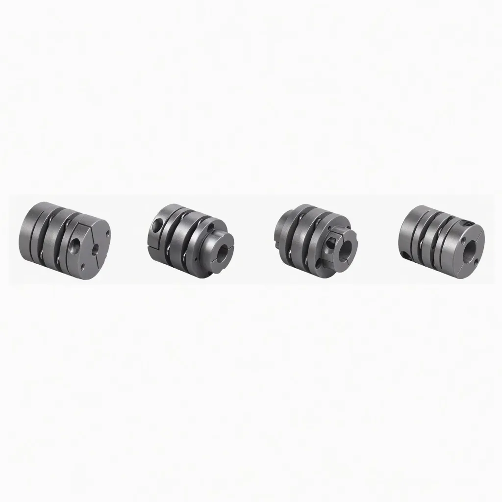
Disc coupling – stainless steel laminar disc pack with alternating bolt pattern. Zero backlash, lubrication-free, precision-balanced. Ever Power Flange Couplings Australia Ltd.
How the Disc Coupling Transmits Torque
Thin stainless steel discs are stacked into a pack with precise hole spacing on a common bolt circle. Bolts pass through the pack in alternating positions — bolt 1 connects the drive flange to the front half of the pack, bolt 2 connects the back half of the pack to the driven flange, bolt 3 returns to the drive flange, and so on around the circle. This alternating bolt pattern forces the disc pack to wind up elastically under applied torque, transmitting the load through pure metal deflection without sliding contact or backlash.
When the input shaft rotates angularly relative to the output shaft — angular misalignment — the disc pack flexes out of its installed plane and the pack accommodates the misalignment through controlled elastic distortion. When the shafts move axially relative to each other — thermal growth on a hot pump or compressor — the disc pack cones slightly and absorbs the axial deflection. Both misalignment modes are handled within the elastic limit of the disc material without any sliding contact, lubrication, or wear.
Why Disc Couplings Specify for Turbomachinery
High-speed centrifugal compressors, gas turbines, and steam turbines operate at speeds and temperatures that exceed the design envelope of any elastomeric industrial shaft coupling. Historically, gear couplings filled this application — but gear couplings introduce backlash that compromises positional accuracy and require periodic lubrication that contaminates downstream equipment. The disc coupling solves both problems: zero backlash for positional accuracy; no lubrication for downstream cleanliness and fire safety in hot installations. This is why the disc coupling has become the industry default for new turbomachinery installations.
Construction and Material Specification
The disc pack is precision-photoetched or laser-cut from stainless steel sheet to ensure dimensional consistency across discs. Standard construction is AISI 301 stainless steel cold-rolled to high tensile strength — chosen for fatigue resistance, corrosion resistance, and dimensional stability through millions of deflection cycles. Disc thickness ranges from 0.5 mm on small instrument couplings up to 1.5 mm on large industrial sizes. Disc count per pack ranges from 6 discs on small sizes through 24 discs on heavy industrial sizes.
Hub flanges are typically machined from medium-carbon steel forgings, with corrosion-protective surface treatments — phosphate-and-paint for industrial atmospheric service, or stainless steel construction for marine and chemical applications. Bolts and nuts are high-tensile alloy steel, supplied torque-rated for the disc pack pre-tension required at the rated torque envelope. For double-disc-pack spacer configurations, the intermediate spacer tube is machined from medium-carbon steel and dynamically balanced to grade G2.5 or better for the rated operating speed.
Engineering Features of the Disc Coupling
Alternating bolt pattern produces a torque path with zero clearance. The disc pack is pre-tensioned during installation; torque reversal does not introduce any positional lost-motion. Critical for servo-driven positioning systems and precision spindle drives.
No elastomeric mass to limit critical speed. Precision-balanced disc-pack assemblies routinely operate above 10,000 rpm in turbomachinery and instrumentation applications. Custom balance specifications support speeds above 20,000 rpm.
No grease, no oil, no lubrication-maintenance schedule. Eliminates contamination of downstream equipment with grease purged from the coupling, and removes the fire hazard of lubricated couplings in hot turbomachinery installations.
Standard 301 stainless: -50 °C to +200 °C. Higher temperatures available with alloy disc options up to +450 °C with appropriate fatigue derating for the operating temperature.
Standard disc coupling specifications support API 671 turbomachinery coupling requirements for refinery, petrochemical, and gas processing facility applications. API 671 documentation package available on request at order.
Disc pack is removable without taking the hubs off the shafts — bolts come out, pack lifts clear, new pack installs in the same position. Routine pack replacement is a single-shift maintenance task at scheduled outage.
Disc coupling installation – alternating bolt pattern on common bolt circle. Disc pack thickness selected for application torque envelope.
Application Field for the Disc Coupling
Disc couplings appear wherever the application combines high speed, high temperature, or high positional accuracy requirement. Refinery and petrochemical plant — centrifugal compressor and pump drives operating under API 671 documentation. LNG and gas processing — turboexpander and main process compressor drives. Power generation — gas turbine and steam turbine main shaft and auxiliary drives. Precision manufacturing — CNC machine tool spindle drives, servo-driven rotary positioning axes, automotive chassis dynamometers.
Aerospace, Defence, and Test Equipment Applications
Aerospace engine test cells, defence propulsion test rigs, and high-end automotive dynamometer installations all rely on the disc coupling for its combination of zero backlash, high speed capability, and lubrication-free operation. These applications cannot tolerate the contamination risk of a lubricated coupling and cannot accept the positional inaccuracy of any backlash in the torque path. The disc coupling is one of very few flexible coupling types that meets all three constraints simultaneously.
Selecting the Correct Disc Coupling Configuration
Disc coupling sizing starts with operating speed and transmitted power, not just rated torque. Above 5000 rpm the centrifugal stress on the disc pack itself becomes significant; above 10,000 rpm the balance specification dominates the selection. Provide operating speed, transmitted power, ambient temperature, shaft diameters, and the misalignment envelope to our Sydney engineering team for size recommendation. Custom disc-pack configurations are routinely engineered for specialised turbomachinery applications.
Single-pack versus double-disc-pack spacer is the second major selection question. Single-pack is sufficient where shaft alignment is precise after laser alignment and the application does not require radial offset compensation. Double-disc-pack spacer is specified where the operating equipment will see significant radial offset under thermal growth, where back pull-out maintenance access on a pump or compressor is required, or where the operating equipment specification calls out spacer-coupling configuration explicitly under API 671 or company internal standards.
Installation and Precision Alignment
Disc coupling installation requires careful precision alignment because the disc pack has limited misalignment capacity compared to elastomeric and gear couplings — operating beyond the rated envelope causes premature disc fatigue and pack failure. The standard installation workflow brings final installed alignment within half the rated envelope, leaving headroom for thermal growth and foundation settlement during operating life.
Inspect the disc pack and hub flanges for shipping damage. Verify all hardware — bolts, washers, locking compound — is supplied. Confirm dimensional inspection certificate is present. Review manufacturer alignment specification for the supplied configuration.
Mount each hub on its respective shaft with the correct rotational orientation. Bring driver and driven equipment to rough alignment with straight edge and feeler gauges before proceeding to precision alignment with laser equipment.
Align angular and parallel offset to within half the rated envelope — typically 0.2 ° angular and 0.1 mm parallel offset for single-pack configurations. Document final alignment values in the equipment maintenance record for future reference at scheduled inspection.
Install the disc pack between the hub flanges. Insert all bolts in the alternating pattern; apply stage-torque sequence with calibrated torque wrench. Apply locking compound to threads per specification. Verify the disc pack is centred with no axial preload.
Re-check alignment after disc pack installation; final installed alignment must be within rated envelope with margin. Run at progressive speed up to operating speed monitoring vibration carefully. Inspect disc pack at first scheduled maintenance interval and replace at any sign of disc cracking.
OEM Cross-Reference and API 671 Documentation
Direct cross-reference is supplied for Rexnord Thomas disc couplings, Lovejoy disc couplings, Renold disc couplings, John Crane disc couplings, and other major OEM disc coupling brands. Provide the OEM size code, operating speed, transmitted power, shaft diameters, and misalignment envelope for confirmed equivalent specification from our Sydney engineering team. For API 671 turbomachinery applications, specify the API 671 documentation requirement at order entry — the documentation package is supplied at no additional charge for standard API 671 sizes.
Custom disc-pack configurations are available for specialised applications including aerospace test rigs (custom balance grades), high-temperature service (Hastelloy or Inconel disc material), corrosive process gas service (special alloy hub material), and replacement-only orders for existing installations where the original OEM is no longer supplying parts. Custom production lead times are 4 to 8 weeks for standard alloy specifications and 8 to 12 weeks for exotic alloy specifications.
Why Choose Ever Power Australia
Ever Power Flange Couplings Australia Ltd. supplies the EP disc coupling range from our Sydney warehouse for Australian turbomachinery, high-speed compressor, and precision drive applications. API 671 documentation, custom balance specifications, and OEM cross-reference work are standard services from our in-house engineering team. The ISO 9001 quality management system ensures consistent disc pack hardness, dimensional accuracy, and bolt torque calibration across the range. Material traceability, dimensional inspection records, and heat-treatment certification are available on request for all disc coupling supply.

Ever Power manufacturing facility — ISO 9001 certified, 12,000 m², 108 dedicated coupling machines, 20+ years of production experience.
Every order placed with our Sydney team is backed by full material traceability, dimensional inspection certificates on request, and direct access to the engineers who specified, machined, and packed your coupling. We do not subcontract technical support — when you phone +61 2 9708 3322 during NSW business hours, you reach the people who actually know the product.
Frequently Asked Questions
Quick answers from our Sydney technical team. Contact us for application-specific guidance.
1. How is zero backlash achieved in the disc coupling? +
2. What is the difference between single-pack and double-disc-pack spacer configurations? +
3. Can the disc coupling operate above 10,000 rpm? +
4. Is the disc coupling appropriate for API 671 turbomachinery service? +
5. How long does a disc coupling disc pack last in normal industrial service? +
Request a Quote — Sydney NSW Stock
Tell us your motor power, shaft diameter, and operating environment. Our New South Wales coupling team confirms availability and pricing within one business day, with same-day dispatch on standard sizes from Condell Park.
Ever Power Flange Couplings Australia Ltd. · 27 Harley Crescent, Condell Park NSW 2200 · [email protected]