
The choice between a rigid flange coupling and a flexible flange coupling is the most fundamental coupling selection decision in any motor-driven drivetrain. Get it right and the connected machines run quietly and reliably for years. Get it wrong and you face a predictable pattern of bearing failures, mechanical seal replacements, and vibration complaints that no amount of alignment work will fully resolve.
The Fundamental Engineering Difference
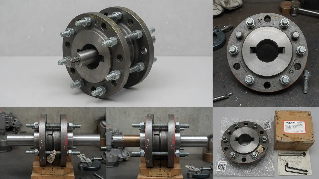
A rigid flange coupling creates a mechanically fixed, inflexible connection between two shaft ends. The two flanged hubs bolt directly together face-to-face with no intermediate element. Any misalignment between the two shafts must be accommodated by deformation of the shafts themselves or the bearings that support them — making rigid couplings excellent at transmitting torque, and equally excellent at transmitting all forces associated with misalignment.
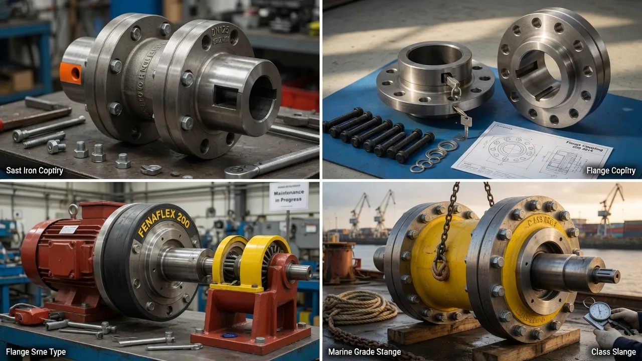
A flexible flange coupling introduces an elastomeric element between the two hubs. This element flexes to accommodate angular, parallel, and axial misalignment without transmitting the associated forces to the bearings. The elastomeric element also absorbs vibration and shock loads, providing a degree of isolation between the motor and the driven machine.
Head-to-Head Comparison Across Key Performance Criteria
| Performance Criterion | Rigid Flange Coupling | Flexible Flange Coupling |
|---|---|---|
| Misalignment Tolerance | Essentially zero — requires ≤0.05 mm TIR | Up to 4° angular / 3 mm parallel (tyre type) |
| Vibration Damping | None — transmits all vibration to bearings | Good — elastomeric element absorbs peaks |
| Torsional Stiffness | Absolute — no angular compliance | Moderate — depends on elastomer hardness and size |
| Bearing Protection | None — full misalignment loads on bearings | Good — element absorbs radial and axial forces |
| Maintenance Requirement | Minimal — inspect bolts periodically | Spider/tyre inspection every 12 months |
| Temperature Range | -20°C to +120°C (metal-to-metal only) | Depends on elastomer — NR up to 70°C, EPDM to 120°C |
| Total Cost of Ownership | Higher if misalignment causes bearing failures | Lower overall in most industrial applications |
When Rigid Couplings Are the Right Choice
Rigid flange couplings have a legitimate role in industrial applications — but they are the right choice in a narrower range of situations than many engineers assume. The conditions that genuinely favour a rigid coupling include: precision test stands and dynamometer drives where torsional compliance would introduce measurement error; close-coupled vertically-mounted pump sets where the pump bearing supports the motor shaft and alignment is guaranteed by design; and servo and encoder connections where zero backlash is required and shaft alignment is controlled by precision linear rails.
When Flexible Couplings Are the Right Choice
The flexible flange coupling is the correct default for almost all pump, fan, compressor, and conveyor drives in Australian industry. If any of the following apply, a flexible coupling is required: the motor and pump are mounted on separate frames or baseplates; the baseplate is grouted or epoxy-filled; the connected equipment operates at significantly different temperatures; the motor is started direct-on-line; or the driven machine generates vibration, as all reciprocating pumps do.
Frequently Asked Questions
Need Expert Coupling Advice?
Our engineering team in Condell Park NSW is ready to help — free of charge.