Product Description
Product Details
| General Products Application/Service Area | Metal Parts Solution for Vehicle, Agriculture machine, Construction Machine, transportation equipment, Valve and Pump system. E.g. Engine bracket, truck chassis bracket, gear box , gear housing , gear cover, shaft, spline shaft , pulley, flange, connection pipe, pipe, hydraulic valve , valve housing ,Fitting , flange, wheel, flywheel, oil pump housing, starter housing, coolant pump housing, transmission shaft , transmission gear, sprocket, chains etc. |
| Process for Casting Iron | Sand Casting , Resin Sand Casting, Green Sand Casting, Shell Molding, Automatic Molding, |
| Casting Tolerance | CT9-10 for Machine Molding Process, CT8-9 for Shell Molding and Lost Foam Molding Casting Process CT10-11 for Manual Molding Sand casting Process |
| Applicable Material | Ductile Iron, Grey Iron Casting, or as customer request. |
| Applicable Finish Surface Treatment | Shot/sand blast, polishing, Powder coating, ED- Coating, etc |
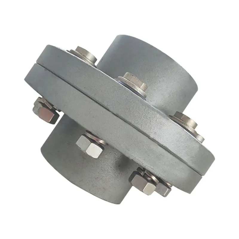
Product Show
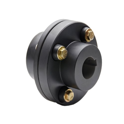
Flange Couplings for Motor-to-Shaft and Shaft-to-Shaft Connections
Flange couplings are versatile components that can be used for both motor-to-shaft and shaft-to-shaft connections in a wide range of mechanical systems. Their design and features make them suitable for various applications:
1. Motor-to-Shaft Connections: Flange couplings are commonly used to connect electric motors to driven equipment, such as pumps, fans, compressors, and conveyors. In motor-to-shaft connections, the flange coupling is mounted on the motor shaft and connected to the input shaft of the driven equipment. This configuration ensures efficient power transmission from the motor to the driven component.
2. Shaft-to-Shaft Connections: Flange couplings are also employed for shaft-to-shaft connections, where two shafts need to be linked together. This could involve connecting two separate pieces of machinery or extending the length of an existing shaft. Flange couplings allow for the secure and precise alignment of the two shafts, ensuring smooth rotation and power transmission between them.
Flange couplings are available in various designs, such as rigid flange couplings, flexible flange couplings, and floating shaft couplings. Rigid flange couplings offer a more rigid connection, ideal for applications where shaft misalignment is minimal. Flexible flange couplings, on the other hand, can accommodate some degree of misalignment and provide vibration dampening, making them suitable for systems with dynamic conditions or slight misalignments.
When selecting a flange coupling for a specific connection, factors such as the required torque capacity, shaft sizes, misalignment tolerance, and operating conditions need to be considered. Proper installation and alignment are crucial to ensure the optimal performance and longevity of the flange coupling in both motor-to-shaft and shaft-to-shaft connections.
In summary, flange couplings are versatile components that can be effectively used for both motor-to-shaft and shaft-to-shaft connections. Their ability to provide secure and efficient power transmission makes them a valuable choice in various industries and mechanical systems.

How Does a Flange Coupling Help in Power Transmission Efficiency?
A flange coupling plays a crucial role in improving power transmission efficiency in mechanical systems. It efficiently transfers power from one shaft to another while maintaining the alignment and minimizing energy losses. Here’s how flange couplings contribute to power transmission efficiency:
1. Direct Power Transfer: Flange couplings provide a direct connection between the driving and driven shafts, ensuring a solid and reliable power transfer without the need for intermediate components. This direct coupling minimizes power losses that can occur in systems with multiple components and connections.
2. Rigid and Precise Connection: Rigid flange couplings offer a precise and firm connection between shafts, minimizing angular and parallel misalignments. By reducing misalignment, energy losses due to friction and vibrations are minimized, leading to more efficient power transmission.
3. Absence of Slippage: Flange couplings are designed to provide a secure and non-slip connection between shafts. Unlike some other coupling types that might experience slippage under heavy loads or during acceleration, flange couplings maintain constant power transmission without loss of torque.
4. High Load-Carrying Capacity: Flange couplings are capable of handling high torque and axial loads, making them suitable for heavy-duty applications. The ability to handle these loads without deformation ensures efficient power transmission even in demanding industrial settings.
5. Minimal Maintenance: Flange couplings are generally low-maintenance components. Once properly installed, they require minimal attention, reducing downtime and enhancing overall system efficiency.
6. Balancing and Vibration Damping: Some flange coupling designs, such as flexible and torsionally flexible couplings, provide additional benefits like vibration damping and torsional flexibility. These features help to absorb shocks and vibrations, ensuring a smoother power transmission and protecting connected equipment from damage.
7. Selection of Appropriate Flange Type: Choosing the right type of flange coupling for a specific application is crucial for optimal power transmission efficiency. Different flange designs offer varying levels of flexibility and alignment capabilities, allowing engineers to select the most suitable coupling based on the system requirements.
In summary, flange couplings facilitate efficient power transmission by maintaining alignment, reducing energy losses, and providing a robust and reliable connection between shafts. Properly selected and installed flange couplings help improve the overall efficiency and performance of mechanical systems.

What are the Maintenance Requirements for Flange Couplings?
Flange couplings require regular maintenance to ensure optimal performance and longevity. Proper maintenance can help prevent unexpected failures and downtime in the machinery or equipment. Here are the key maintenance requirements for flange couplings:
1. Inspection: Regularly inspect the flange coupling for signs of wear, damage, or misalignment. Check for cracks, corrosion, or any deformations in the flange and bolt holes. Ensure that the coupling is properly aligned with the shafts.2. Lubrication: Lubricate the flange coupling as per the manufacturer’s recommendations. Proper lubrication helps reduce friction and wear between the mating surfaces of the flanges, bolts, and nuts. Use the right type of lubricant that is compatible with the coupling material.3. Bolt Torque Check: Check the bolt torque regularly to ensure that the flange coupling is securely fastened. Loose bolts can lead to misalignment and coupling failure. Follow the recommended torque values provided by the manufacturer.4. Alignment: Maintain proper shaft alignment to prevent excessive forces on the flange coupling. Misalignment can cause uneven load distribution and accelerated wear on the coupling components.5. Environmental Protection: If the flange coupling is exposed to harsh or corrosive environments, take necessary measures to protect it. Consider using protective coatings or seals to prevent corrosion and damage.6. Regular Servicing: Schedule regular servicing of the machinery or equipment, including the flange coupling. This allows for a thorough inspection and timely replacement of worn-out or damaged components.7. Replacement of Worn Parts: When signs of wear or damage are detected during inspections, replace the worn or damaged parts promptly. Delaying the replacement can lead to further damage and compromise the performance of the coupling.8. Follow Manufacturer’s Guidelines: Always follow the maintenance guidelines provided by the flange coupling manufacturer. They may have specific recommendations based on the design and material of the coupling. Proper maintenance and regular checks can extend the life of the flange coupling and contribute to the overall reliability and efficiency of the connected machinery. It is essential to create a maintenance schedule and adhere to it diligently to ensure the smooth operation of the flange coupling and the entire mechanical system.


editor by CX 2023-08-18
China high quality Universal Flange Adaptor Flexible Coupling for Di AC Steel PVC HDPE Pipe flange coupling
Product Description
Dismantling Joints are designed to provide a simple method of installation and removal of flanged pipeline components such as valves, pumps and strainers from a pipeline. Dismantling Joints allow a variable setting distance of 50mm on site and are supplied complete, ready to be installed. Dismantling Joints are restrained products that prevent axial pipe movement, they are most suited to valve and pump chambers, and complex steel fitting installations.
PRODUCT DESCRIPTION:
Body: ductile iron grade 500-7/450-12 in accordance with ISO 1083 .
Bolts:carbon steel with zinc coating/stainless steel CZPT customers’ request.
Gasket :EPDM/NBR/SBR
Size and Pressure
Size:DN50-DN2000 Pressure:PN10 PN16 PN25 PN40
Coating
External coatings
zinc coating+biHangZhou coating
liquid epoxy painting
epoxy applied by FBE
according to customers’ requirements
Internal coatings
cement mortar lining
liquid epoxy painting
epoxy applied by FBE
according to customers’ requirements
Package
Bubble bags , cartons or wookden case for free options.
Use
The ductile iron dismantling joint is a pipe expansion joint than could reduce vibration and noise greatly , which is widely used in pipeline system to solve pipe interface axial stretching displacement .
Our machining shop located in HangZhou, using the latest CNC equipment to provide our customer with high quality products.
Horizontal and Vertical Machining Center
CNC lathe and normal lathe
CNC drilling and milling Center
Other assistant equipment
Test Equipment
We use first-class facilities in the world to control all the processes to offer products with the best component quality and the correct dimension.Customer’s satisfaction is our final target!
Our test equipment include :Three dimentional machine,inspection gauge,Metallurgical structure analysis,Direct reading spectrometer,Tensile testing machine,Inside micrometer,Geneal gauge.
| Standard | ISO 2531 & BS EN 545 & EN 598 |
| Material | GGG40 & GGG50 & other ductile iron |
| Package | Wooden pallet & Wooden case &As request |
| Accessories | Gasket, Bolt & Nut available CZPT request |
| Payment | 30%in advance by TT,balance before loading |
| Coating | Fusion bonded epoxy coating ; Cement CZPT inside and zinc primer and biHangZhou painting outside ; BiHangZhou painting inside and outside ; Red anti-rustcoating |
What Industries Commonly Use Flange Couplings for Power Transmission?
Flange couplings are widely used in various industries for power transmission due to their reliability and versatility. Some of the common industries where flange couplings are employed include:
1. Manufacturing: In manufacturing industries such as automotive, aerospace, electronics, and consumer goods, flange couplings are utilized in machinery and equipment to transmit power between different components.
2. Oil and Gas: The oil and gas industry often uses flange couplings in pumps, compressors, and turbines for power transmission in exploration, extraction, and refining processes.
3. Chemical and Petrochemical: Flange couplings are used in various equipment within the chemical and petrochemical industry, including mixers, agitators, and pumps, to transfer power efficiently.
4. Mining and Construction: Heavy-duty machinery in mining and construction applications relies on flange couplings to transmit power in demanding and challenging environments.
5. Power Generation: Power plants, including thermal, hydroelectric, and wind power facilities, use flange couplings in turbines, generators, and auxiliary systems for power transmission.
6. Marine: In the marine industry, flange couplings are utilized in propulsion systems, winches, and other equipment that requires power transmission in marine vessels.
7. Steel and Metal Processing: Steel mills and metal processing plants use flange couplings in various equipment, including rolling mills and conveyor systems.
8. Food and Beverage: The food processing and beverage industry use flange couplings in mixers, pumps, and conveyor systems to handle power transmission in hygienic environments.
9. Pharmaceutical: Pharmaceutical manufacturing equipment employs flange couplings for power transmission in processes such as mixing, granulation, and tablet compression.
10. Water and Wastewater: Flange couplings are used in water treatment plants and wastewater facilities to transfer power in pumps and other equipment.
These are just a few examples, and flange couplings are found in many other industries where reliable power transmission is essential for smooth operations.
Can Flange Couplings Be Used in Heavy-Duty Applications Such as Mining and Construction?
Yes, flange couplings can be used in heavy-duty applications such as mining and construction, where they are often employed to transmit power between large machinery and equipment. Flange couplings are designed to handle high torque and axial loads, making them suitable for these demanding industries. Here are some reasons why flange couplings are well-suited for heavy-duty applications:
1. High Load Capacity: Flange couplings are engineered to provide high load-carrying capacity, making them ideal for heavy machinery used in mining and construction. They can efficiently transfer power between components with large torque requirements, such as conveyors, crushers, and excavators.
2. Tolerance to Misalignment: Heavy-duty equipment may experience misalignment due to uneven loading, vibrations, or other factors. Flange couplings can accommodate certain degrees of misalignment, reducing stress on connected components and preventing premature wear or failure.
3. Durability and Strength: In mining and construction, equipment is subjected to harsh conditions, impacts, and vibrations. Flange couplings are typically made from robust materials like steel or cast iron, providing exceptional strength and durability to withstand the rugged environments encountered in these industries.
4. Easy Maintenance: While heavy-duty applications may expose equipment to extreme conditions, maintenance and downtime should be minimized. Flange couplings are designed to be relatively easy to install and maintain, ensuring that machinery can quickly get back to work after routine maintenance or repairs.
5. Various Flange Designs: Flange couplings come in different designs, including rigid, flexible, and torsionally flexible variations. This allows engineers to select the most appropriate type for the specific needs of mining and construction equipment.
However, it is crucial to consider factors such as the specific load requirements, operating conditions, and alignment precision when choosing flange couplings for heavy-duty applications. Proper installation, regular inspection, and adherence to recommended maintenance schedules are essential to ensure the reliable performance and extended service life of the flange couplings in mining and construction equipment.

What is a flange coupling and how does it work?
A flange coupling is a type of rigid coupling used to connect two shafts together in a mechanical system. It consists of two flanges, one on each shaft, which are bolted together to form a solid and robust connection. Flange couplings are widely used in applications where precise alignment, high torque transmission, and zero backlash are critical.
The key components of a flange coupling include:
- Flanges: The flanges are circular discs with holes around the perimeter for bolting them to the respective shaft ends. The flanges are made from materials such as steel, cast iron, or aluminum, depending on the application requirements.
- Fasteners: High-strength bolts or studs with nuts are used to fasten the flanges together securely. The number and size of the bolts depend on the size and torque capacity of the coupling.
- Gaskets: In some cases, gaskets or spacers are used between the flanges to provide insulation, prevent corrosion, or compensate for any slight misalignments between the shafts.
How a flange coupling works:
- The two shafts that need to be connected are brought together with their respective flanges facing each other.
- The flanges are aligned precisely to ensure that both shafts are in perfect axial alignment. Proper alignment is essential to prevent excessive loads on the bearings and to ensure efficient torque transmission.
- Once the flanges are aligned, high-strength bolts or studs are inserted through the holes in the flanges, and nuts are fastened tightly to hold the flanges together securely.
- The tight connection between the flanges creates a rigid joint between the shafts, allowing torque to be transmitted from one shaft to the other with minimal losses.
- Flange couplings are designed to have zero backlash, meaning there is no play or free movement between the shafts when the direction of rotation changes. This feature ensures precise and immediate power transmission between the connected shafts.
Flange couplings are commonly used in various industrial applications, including heavy machinery, pumps, compressors, and marine propulsion systems. They are preferred when a reliable, high-torque transmission with precise alignment is required. However, they do not offer flexibility to accommodate misalignment, which is a limitation compared to flexible couplings. Therefore, proper alignment during installation is critical to avoid premature wear and failure of the coupling and connected equipment.
editor by CX 2023-08-15
China wholesaler ISO2531 Ductile Iron Flange Adaptor Flexible Coupling Flange Adaptor Coupling flange coupling
Product Description
Ductile Iron flange adapter with PN10/16 coupling for Ductile Iron Pipe fitting
The flange adapter transmits the pressure and thrust of the connected parts (blind plate force) and compensates the pipeline error, so as to reduce the damage of the axial thrust to the pipeline and pipeline equipment. It is mainly used for loose sleeve connection of pump, valve, pipeline and other accessories.
Specifications
Body: Ductile iron
Bolts: Galvanized steel / Stainless steel
Seal gasket: EPDM
Coating: CZPT Epoxy
Class: PN10/16, 125/150Lbs
Size:DN50-DN600
|
Size |
DN50-DN300 |
|
Standard |
ISO2531/EN545/EN598/AWWA |
|
Pressure |
PN10/PN16/PN25 |
|
Material |
Ductile Iron GGG50 material with FBE coated |
|
Coating |
Fusion bonded epoxy coating(250 micron) |
|
Color |
Blue FBE / Epoxy Coating |
|
Connection Type |
Flange Joint |
|
Gasket |
EPDM, SBR/NBR also available |
|
bolt nut |
Steel 8.8 zinced/Dacro |
Our Factory
HangZhou Fluido Import and Export Co.,Ltd. is a professional flange, pipe fittings,valves and ductile iron pipe fitting manufacturer and exporter for water treatment, construction, petrochemical and oilfield industry. We deliver exceptional value by providing customers with the most important elements : Premium Quality, Reasonable Price and Impeccable Services.
Our products adhere to GB, JIS, DIN, DIN, EN, API, ANSI/ASME specifications for material content, pressure ratings and quality assurance, ensuring that our customers receive consistent quality and reliability every time. Additionally, we are able to modify existing products or manufacture new designs to meet specific requirements.
We have been known as a company who always keeps our promise of quality products, reasonable pricing, and prompt delivery. By providing a broad range of high quality products at competitive prices, We see ourselves not just as a supplier for our clients, but as their partner in helping them achieved their own goals and objectives.
Package as customized
Certifications
Other Related Product
Our Services
1. Many years experience in manufacturing and exporting fittings
2. Experienced technical staff
3. Marking the customer’s brand on the product surface directly
4. All fittings are approved by CE and ISO
5. Supply OEM service
6. Small orders accepted
7. Competitive prices, top quality, professional service and prompt delivery
8. Quality checking and controlling strictly
FAQ
Q:When can I get the quotation?
A:We usually quote within 12 hours after we get your inquiry.If you are very urgent to get the price,pls call us or tell us in your email so that we will regard your inquiry priority.
Q: Could I get samples?
A: Yes,we have materials in stock to help you to get the samples as soon as we can.
Q:Can you do the design for us?
A:We have a professional team having rich experience in manufacturing.We could supply customized size,grade of material,and the coating.We also could supply the package according to your request.
Q.How are orders packed and shipped ?
A: For custom order, we can design full-color custom packaging to match your brand, if requires. Most shipments include boxes packed inside an outer carton and placed on a wooden pallet.
Q:What abount the lead time for mass production?
A:Honestly,it depends on the order quantity and your specific requirements of products.
Q.What are your quality control procedures?
A: We adhere to strict quality control procedures that begin with product design and carry through to the end of the production process using state-of -the-art quality control equipment.

Factors to Consider When Choosing a Flange Coupling for a Specific System
When selecting a flange coupling for a specific system, several factors need to be taken into consideration to ensure optimal performance and reliability. Here are the key factors to consider:
- 1. Load and Torque Requirements: Determine the maximum load and torque that the flange coupling will experience in the application. This includes both static and dynamic loads. Select a flange coupling that can handle these loads without exceeding its rated capacity.
- 2. Shaft Diameter: Measure the diameter of the shafts that will be connected by the flange coupling. Ensure that the coupling’s bore size matches the shaft diameter to provide a proper fit and secure connection.
- 3. Misalignment Tolerance: Consider the amount of misalignment that the system may experience during operation. Flange couplings are available in different designs, and some can accommodate higher levels of misalignment than others. Choose a coupling that can handle the expected misalignment to prevent premature wear and stress on the system.
- 4. Operating Speed: Determine the rotational speed of the connected equipment. High-speed applications may require precision balancing and careful selection of materials to prevent issues like resonance and excessive vibration.
- 5. Environmental Conditions: Consider the environmental factors the flange coupling will be exposed to, such as temperature, humidity, dust, and chemicals. Choose a material and coating that can withstand the specific environmental conditions to prevent corrosion and degradation.
- 6. Space Limitations: Evaluate the available space for installing the flange coupling. Some applications may have limited space for coupling installation, requiring compact designs or custom solutions.
- 7. Serviceability: Assess the ease of installation and maintenance of the flange coupling. A coupling that is easy to install and service can reduce downtime and maintenance costs.
- 8. Compatibility: Ensure that the flange coupling is compatible with the equipment and shafts in the system. Consider factors such as keyways, set screws, and other connection methods.
- 9. Material Selection: Choose the appropriate material for the flange coupling based on factors like load, temperature, and corrosion resistance. Common materials include steel, stainless steel, aluminum, and various alloys.
- 10. Cost: Compare the cost of different flange coupling options, considering both the initial investment and long-term maintenance expenses. Balance the cost with the desired performance and reliability.
It is essential to consult with coupling manufacturers or industry experts to ensure the flange coupling’s suitability for the specific application. Properly selecting and installing the right flange coupling can contribute to the efficiency, reliability, and longevity of the connected machinery and system.

Common Installation Mistakes to Avoid When Using Flange Couplings
Proper installation is crucial for the efficient and reliable operation of flange couplings. Avoiding common installation mistakes can help ensure the longevity and optimal performance of the coupling. Here are some common installation mistakes to avoid:
1. Improper Alignment: One of the most critical aspects of flange coupling installation is ensuring proper shaft alignment. Misalignment can lead to increased wear, vibrations, and decreased power transmission efficiency. Always use precision alignment tools and techniques to achieve accurate alignment.
2. Over-Tightening: Over-tightening the coupling’s bolts can cause excessive stresses on the coupling and connected equipment. It may lead to premature failure or deformation of the coupling. Follow the manufacturer’s recommended torque values for tightening the bolts.
3. Under-Tightening: On the other hand, under-tightening the bolts may result in a loose connection, leading to misalignment and potential damage to the coupling during operation. Make sure to achieve the proper torque during installation.
4. Lack of Lubrication: Insufficient or improper lubrication of the coupling’s components can result in increased friction and wear. Follow the manufacturer’s guidelines for lubrication, and use the recommended lubricant to ensure smooth operation.
5. Contamination: Avoid introducing dirt, debris, or foreign particles into the coupling during installation. Contaminants can lead to wear and damage over time, reducing the coupling’s performance.
6. Incorrect Coupling Selection: Choosing the wrong type or size of flange coupling for the application can lead to performance issues. Consider factors like torque, speed, load, and operating environment when selecting the coupling.
7. Lack of Inspection: After installation, regularly inspect the flange coupling and its components for signs of wear, damage, or misalignment. Early detection of issues allows for timely maintenance and prevents potential system failures.
8. Ignoring Manufacturer Guidelines: Always follow the manufacturer’s installation instructions and guidelines. Each flange coupling may have specific requirements and recommendations that must be adhered to for proper functioning.
9. Incorrect Shaft Fit: Ensure that the coupling properly fits the shafts’ dimensions. A loose fit can cause slippage, while a tight fit can lead to stress concentration and premature failure.
10. Inadequate Inspection of Components: Before installation, inspect all coupling components, including flanges, bolts, and keyways, for any defects or damage. Replace any damaged parts before installation.
By avoiding these common installation mistakes, you can maximize the performance and lifespan of flange couplings in your mechanical systems.
What is a flange coupling and how does it work?
A flange coupling is a type of rigid coupling used to connect two shafts together in a mechanical system. It consists of two flanges, one on each shaft, which are bolted together to form a solid and robust connection. Flange couplings are widely used in applications where precise alignment, high torque transmission, and zero backlash are critical.
The key components of a flange coupling include:
- Flanges: The flanges are circular discs with holes around the perimeter for bolting them to the respective shaft ends. The flanges are made from materials such as steel, cast iron, or aluminum, depending on the application requirements.
- Fasteners: High-strength bolts or studs with nuts are used to fasten the flanges together securely. The number and size of the bolts depend on the size and torque capacity of the coupling.
- Gaskets: In some cases, gaskets or spacers are used between the flanges to provide insulation, prevent corrosion, or compensate for any slight misalignments between the shafts.
How a flange coupling works:
- The two shafts that need to be connected are brought together with their respective flanges facing each other.
- The flanges are aligned precisely to ensure that both shafts are in perfect axial alignment. Proper alignment is essential to prevent excessive loads on the bearings and to ensure efficient torque transmission.
- Once the flanges are aligned, high-strength bolts or studs are inserted through the holes in the flanges, and nuts are fastened tightly to hold the flanges together securely.
- The tight connection between the flanges creates a rigid joint between the shafts, allowing torque to be transmitted from one shaft to the other with minimal losses.
- Flange couplings are designed to have zero backlash, meaning there is no play or free movement between the shafts when the direction of rotation changes. This feature ensures precise and immediate power transmission between the connected shafts.
Flange couplings are commonly used in various industrial applications, including heavy machinery, pumps, compressors, and marine propulsion systems. They are preferred when a reliable, high-torque transmission with precise alignment is required. However, they do not offer flexibility to accommodate misalignment, which is a limitation compared to flexible couplings. Therefore, proper alignment during installation is critical to avoid premature wear and failure of the coupling and connected equipment.
editor by CX 2023-08-14
China best CZPT HRC Flexible Rubber Coupling HRC130 with B, F and H Flange for Transmissiom Machine flange coupling
Product Description
Product Description
We are the leading top Chinese coupling manufacturer, and are specializing in various high quality HRC coupling.
KASIN HRC Shaft Couplings
1. Material:the hub of the Couplings is Cast Iron,the Elastomer is Rubbe
2. OEM and ODM are available
3. High efficient in transmission
4. Finishing:The surface treatment is normally Phosphated and painting
5. High quality with competitive price
6. Different models suitable for your different demands
7. Stock for different bore size on both sides available.
8. Application in wide range of environment.
9. Quick and easy mounting and disassembly.
10. Resistant to oil and electrical insulation.
11. Identical clockwise and anticlockwise rotational characteristics.
12. Small dimension, low weight, high transmitted torque.
13. It has good performance on compensating the misalignment.
14.Feature of couplings:free of maintenance,simple structure and easy to install.
15.Application:Mainly used in the mining, metallurgical, cement, chemicals, construction, building materials, electric power, telecommunications, textiles, and transportation departments.
Techncial Date
Related Products
Roller Chain Coupling FCL Coupling Curved Jaw Coupling
Manufacturing
Applications:
NM couplings are offered in the industry’s largest variety of stock bore/keyway combinations. These couplings require no lubrication and provide highly reliable service for light, medium, and heavy duty electrical motor and internal combustion power transmission applications. Applications include power transmission to industrial equipment such as pumps, gear boxes, compressors, blowers, mixers, and conveyors.
About Us
Kasin group was established in 1989, and its first product is casting carrier trolley for power & free conveyor system. In 1995, CZPT purchased HangZhou Guoping Forging Factory (LYGP), a marketer of forging bolts & nuts to power & free line market in china. With this acquisition, CZPT positioned itself as 1 of major parts suppliers of monorail and power & free conveyor system in china.
In 2/8822 0571 -57152031 Fax: 86~/8822 0571 -57152030
Http://kasinchain
Flange Couplings for Motor-to-Shaft and Shaft-to-Shaft Connections
Flange couplings are versatile components that can be used for both motor-to-shaft and shaft-to-shaft connections in a wide range of mechanical systems. Their design and features make them suitable for various applications:
1. Motor-to-Shaft Connections: Flange couplings are commonly used to connect electric motors to driven equipment, such as pumps, fans, compressors, and conveyors. In motor-to-shaft connections, the flange coupling is mounted on the motor shaft and connected to the input shaft of the driven equipment. This configuration ensures efficient power transmission from the motor to the driven component.
2. Shaft-to-Shaft Connections: Flange couplings are also employed for shaft-to-shaft connections, where two shafts need to be linked together. This could involve connecting two separate pieces of machinery or extending the length of an existing shaft. Flange couplings allow for the secure and precise alignment of the two shafts, ensuring smooth rotation and power transmission between them.
Flange couplings are available in various designs, such as rigid flange couplings, flexible flange couplings, and floating shaft couplings. Rigid flange couplings offer a more rigid connection, ideal for applications where shaft misalignment is minimal. Flexible flange couplings, on the other hand, can accommodate some degree of misalignment and provide vibration dampening, making them suitable for systems with dynamic conditions or slight misalignments.
When selecting a flange coupling for a specific connection, factors such as the required torque capacity, shaft sizes, misalignment tolerance, and operating conditions need to be considered. Proper installation and alignment are crucial to ensure the optimal performance and longevity of the flange coupling in both motor-to-shaft and shaft-to-shaft connections.
In summary, flange couplings are versatile components that can be effectively used for both motor-to-shaft and shaft-to-shaft connections. Their ability to provide secure and efficient power transmission makes them a valuable choice in various industries and mechanical systems.

How do Flange Couplings Handle Shaft Misalignment in Rotating Equipment?
Flange couplings are designed to handle certain degrees of shaft misalignment in rotating equipment. The flexibility of flange couplings allows them to accommodate minor misalignments between the connected shafts without causing significant stress or damage. The ability to handle shaft misalignment is one of the key advantages of using flange couplings in various industrial applications. Here’s how flange couplings handle shaft misalignment:
1. Radial Misalignment: Flange couplings can handle radial misalignment, which is the offset between the rotational axis of two connected shafts. This misalignment can be in the form of parallel misalignment or angular misalignment. Flange couplings with flexible elements, such as elastomeric inserts or diaphragms, can absorb and compensate for radial misalignment, ensuring smooth power transmission between the shafts.
2. Axial Misalignment: Axial misalignment occurs when there is a linear displacement along the rotational axis of the shafts. While some flange couplings may have limited axial misalignment capabilities, others may not be designed to accommodate significant axial movements. Engineers must consider the specific requirements of the application to ensure that the selected flange coupling can handle the anticipated axial misalignment.
3. Angular Misalignment: Angular misalignment refers to the angle between the rotational axes of the two shafts. Flange couplings with flexible elements can handle a certain degree of angular misalignment by flexing and adjusting to the changing angle. However, excessive angular misalignment can lead to increased wear and reduced coupling life, so it’s essential to keep the misalignment within acceptable limits.
4. Rigid Couplings vs. Flexible Couplings: Rigid couplings, such as sleeve couplings or clamp-style couplings, are not capable of handling misalignment and require precise alignment during installation. On the other hand, flexible flange couplings can tolerate misalignment, making them more forgiving and easier to install in applications where perfect alignment is challenging to achieve.
It is important to note that while flange couplings can handle certain degrees of misalignment, excessive or sustained misalignment can lead to premature wear, reduced coupling life, and potential equipment damage. Therefore, proper alignment during installation and regular maintenance checks are essential to ensure the optimal performance and longevity of flange couplings in rotating equipment.

Materials Used in Manufacturing Flange Couplings
Flange couplings are manufactured using various materials, each offering specific properties and advantages. The choice of material depends on factors such as application requirements, environmental conditions, and cost considerations. Here are some commonly used materials in manufacturing flange couplings:
- 1. Steel: Steel is one of the most common materials for flange couplings. It offers excellent strength, durability, and resistance to wear. Steel couplings are suitable for a wide range of applications and can handle high torque and heavy loads.
- 2. Stainless Steel: Stainless steel is chosen for its superior corrosion resistance, making it ideal for applications where the coupling is exposed to moisture, chemicals, or aggressive substances. Stainless steel flange couplings are common in industries such as food processing, pharmaceuticals, and marine.
- 3. Cast Iron: Cast iron couplings are known for their excellent strength and vibration-damping characteristics. They are often used in industrial settings, including pumps, compressors, and conveyor systems.
- 4. Aluminum: Aluminum couplings are lightweight and suitable for applications where weight is a concern. They are commonly used in industries such as aerospace and automotive.
- 5. Brass: Brass couplings offer good corrosion resistance and electrical conductivity. They are used in specific applications that require these properties.
- 6. Bronze: Bronze couplings are valued for their high strength, corrosion resistance, and resistance to wear. They are commonly used in marine and heavy machinery applications.
- 7. Plastic: Plastic couplings, such as nylon or polyurethane, are used in applications where weight, non-conductivity, and chemical resistance are critical factors.
- 8. Composite Materials: Some modern flange couplings may use composite materials that combine different properties, such as strength, flexibility, and corrosion resistance.
When selecting the material for a flange coupling, it is essential to consider factors such as load capacity, temperature range, chemical exposure, and the specific demands of the application. Proper material selection ensures that the flange coupling performs optimally and has a long service life in its intended environment.
editor by CX 2023-08-10
China Professional Flange Cast Iron Coupling Steel Universal Joint Cardan Pump Rubber Motor Disc Curved Tooth Flex Rigid Drive Shaft Nm Yox Fluid Jaw Flexible Chain Gear Couplings flange coupling
Product Description
Excellent powder metallurgy parts metallic sintered parts
We could offer various powder metallurgy parts including iron based and copper based with top quality and cheapest price, please only send the drawing or sample to us, we will according to customer’s requirement to make it. if you are interested in our product, please do not hesitate to contact us, we would like to offer the top quality and best service for you. thank you!
How do We Work with Our Clients
1. For a design expert or a big company with your own engineering team: we prefer to receive a fully RFQ pack from you including drawing, 3D model, quantity, pictures;
2. For a start-up company owner or green hand for engineering: just send an idea that you want to try, you don’t even need to know what casting is;
3. Our sales will reply you within 24 hours to confirm further details and give the estimated quote time;
4. Our engineering team will evaluate your inquiry and provide our offer within next 1~3 working days.
5. We can arrange a technical communication meeting with you and our engineers together anytime if required.
| Place of origin: | Jangsu,China |
| Type: | Powder metallurgy sintering |
| Spare parts type: | Powder metallurgy parts |
| Machinery Test report: | Provided |
| Material: | Iron,stainless,steel,copper |
| Key selling points: | Quality assurance |
| Mould type: | Tungsten steel |
| Material standard: | MPIF 35,DIN 3571,JIS Z 2550 |
| Application: | Small home appliances,Lockset,Electric tool, automobile, |
| Brand Name: | OEM SERVICE |
| Plating: | Customized |
| After-sales Service: | Online support |
| Processing: | Powder Metallurgr,CNC Machining |
| Powder Metallurgr: | High frequency quenching, oil immersion |
| Quality Control: | 100% inspection |
The Advantage of Powder Metallurgy Process
1. Cost effective
The final products can be compacted with powder metallurgy method ,and no need or can shorten the processing of machine .It can save material greatly and reduce the production cost .
2. Complex shapes
Powder metallurgy allows to obtain complex shapes directly from the compacting tooling ,without any machining operation ,like teeth ,splines ,profiles ,frontal geometries etc.
3. High precision
Achievable tolerances in the perpendicular direction of compacting are typically IT 8-9 as sintered,improvable up to IT 5-7 after sizing .Additional machining operations can improve the precision .
4. Self-lubrication
The interconnected porosity of the material can be filled with oils ,obtaining then a self-lubricating bearing :the oil provides constant lubrication between bearing and shaft ,and the system does not need any additional external lubricant .
5. Green technology
The manufacturing process of sintered components is certified as ecological ,because the material waste is very low ,the product is recyclable ,and the energy efficiency is good because the material is not molten.
FAQ
Q1: What is the type of payment?
A: Usually you should prepay 50% of the total amount. The balance should be pay off before shipment.
Q2: How to guarantee the high quality?
A: 100% inspection. We have Carl Zeiss high-precision testing equipment and testing department to make sure every product of size,appearance and pressure test are good.
Q3: How long will you give me the reply?
A: we will contact you in 12 hours as soon as we can.
Q4. How about your delivery time?
A: Generally, it will take 25 to 35 days after receiving your advance payment. The specific delivery time depends on the items and the quantity of your order. and if the item was non standard, we have to consider extra 10-15days for tooling/mould made.
Q5. Can you produce according to the samples or drawings?
A: Yes, we can produce by your samples or technical drawings. We can build the molds and fixtures.
Q6: How about tooling Charge?
A: Tooling charge only charge once when first order, all future orders would not charge again even tooling repair or under maintance.
Q7: What is your sample policy?
A: We can supply the sample if we have ready parts in stock, but the customers have to pay the sample cost and the courier cost.
Q8: How do you make our business long-term and good relationship?
A: 1. We keep good quality and competitive price to ensure our customers benefit ;
2. We respect every customer as our friend and we sincerely do business and make friends with them, no matter where they come from.
Torque and Speed Ratings of Flange Couplings
Flange couplings are available in various sizes and designs to accommodate a wide range of torque and rotational speed requirements. The torque and speed ratings of flange couplings depend on several factors, including their size, material, and design.
Torque Rating:
The torque rating of a flange coupling indicates the maximum amount of torque it can transmit without experiencing failure or damage. It is typically specified in Nm (Newton-meters) or lb-ft (pound-feet). The torque rating varies for different sizes and types of flange couplings. Larger flange couplings generally have higher torque ratings compared to smaller ones.
Speed Rating:
The speed rating of a flange coupling represents the maximum rotational speed at which it can operate reliably without excessive vibration or wear. It is typically expressed in RPM (revolutions per minute). The speed rating is influenced by factors such as the design, material, and balancing of the flange coupling. Higher-speed applications require flange couplings that can handle the increased centrifugal forces and dynamic loads associated with higher RPMs.
Size and Type:
The torque and speed ratings vary for different sizes and types of flange couplings. For example:
- Smaller flange couplings, such as those used in light-duty applications, may have torque ratings ranging from a few Nm to several hundred Nm, and speed ratings up to a few thousand RPM.
- Larger flange couplings, used in heavy-duty industrial applications, can have torque ratings exceeding several thousand Nm and speed ratings that may reach tens of thousands of RPM.
- Flexible flange couplings may have slightly lower torque ratings compared to rigid flange couplings but offer greater misalignment compensation.
Manufacturer Specifications:
It is essential to refer to the manufacturer’s specifications and technical data to determine the specific torque and speed ratings for each size and type of flange coupling. Manufacturers typically provide detailed performance data to help users select the appropriate flange coupling for their specific application.
Application Considerations:
When selecting a flange coupling, it is crucial to consider the torque and speed requirements of the application. The operating conditions, such as load fluctuations and thermal effects, should also be taken into account to ensure the flange coupling’s reliable performance and longevity.
Conclusion:
Flange couplings come in various sizes and designs, each with its own torque and speed ratings. Properly selecting a flange coupling that meets the specific torque and speed requirements of the application is essential to ensure efficient and trouble-free power transmission in mechanical systems.

Key Features to Consider When Purchasing a Flange Coupling
When purchasing a flange coupling, it is essential to consider several key features to ensure it meets the specific requirements of your application. Here are the main factors to look for:
- Type of Flange Coupling: There are various types of flange couplings, such as rigid, flexible, and fluid couplings. Choose the type that best suits your application’s needs, considering factors like misalignment compensation, torsional stiffness, and vibration damping.
- Size and Dimensions: Select the flange coupling with the appropriate size and dimensions to fit your shafts and equipment. Consider shaft diameter, coupling length, and any space limitations.
- Material: Flange couplings can be made from various materials, including steel, aluminum, stainless steel, and elastomers. Choose a material that offers the required strength, corrosion resistance, and durability for your operating conditions.
- Torsional Rating: Check the torsional rating of the flange coupling to ensure it can handle the torque requirements of your application without failure or deformation.
- Misalignment Compensation: If your application experiences shaft misalignment, opt for a flexible flange coupling that can accommodate angular, parallel, and axial misalignment to prevent stress on connected equipment.
- Backlash: For precision applications, select a flange coupling with minimal or no backlash to maintain accurate positioning and reduce the effects of mechanical play.
- Operating Speed: Consider the operating speed range of the flange coupling to ensure it can handle the rotational speed requirements without issues like resonance or fatigue.
- Environmental Compatibility: Evaluate the flange coupling’s ability to withstand the environmental conditions of your application, such as temperature, humidity, and exposure to chemicals or corrosive substances.
- Installation and Maintenance: Choose a flange coupling that is easy to install and maintain, as proper installation and periodic maintenance are crucial for optimal performance and longevity.
- Cost and Value: Compare the cost of the flange coupling with its features and performance to ensure you are getting the best value for your investment.
By carefully considering these key features, you can select a flange coupling that not only meets the demands of your application but also ensures reliable and efficient power transmission while minimizing downtime and maintenance costs.
What is a flange coupling and how does it work?
A flange coupling is a type of rigid coupling used to connect two shafts together in a mechanical system. It consists of two flanges, one on each shaft, which are bolted together to form a solid and robust connection. Flange couplings are widely used in applications where precise alignment, high torque transmission, and zero backlash are critical.
The key components of a flange coupling include:
- Flanges: The flanges are circular discs with holes around the perimeter for bolting them to the respective shaft ends. The flanges are made from materials such as steel, cast iron, or aluminum, depending on the application requirements.
- Fasteners: High-strength bolts or studs with nuts are used to fasten the flanges together securely. The number and size of the bolts depend on the size and torque capacity of the coupling.
- Gaskets: In some cases, gaskets or spacers are used between the flanges to provide insulation, prevent corrosion, or compensate for any slight misalignments between the shafts.
How a flange coupling works:
- The two shafts that need to be connected are brought together with their respective flanges facing each other.
- The flanges are aligned precisely to ensure that both shafts are in perfect axial alignment. Proper alignment is essential to prevent excessive loads on the bearings and to ensure efficient torque transmission.
- Once the flanges are aligned, high-strength bolts or studs are inserted through the holes in the flanges, and nuts are fastened tightly to hold the flanges together securely.
- The tight connection between the flanges creates a rigid joint between the shafts, allowing torque to be transmitted from one shaft to the other with minimal losses.
- Flange couplings are designed to have zero backlash, meaning there is no play or free movement between the shafts when the direction of rotation changes. This feature ensures precise and immediate power transmission between the connected shafts.
Flange couplings are commonly used in various industrial applications, including heavy machinery, pumps, compressors, and marine propulsion systems. They are preferred when a reliable, high-torque transmission with precise alignment is required. However, they do not offer flexibility to accommodate misalignment, which is a limitation compared to flexible couplings. Therefore, proper alignment during installation is critical to avoid premature wear and failure of the coupling and connected equipment.
editor by CX 2023-08-02
China Gear Coupling Flexible Fluid Flange HRC Spacer Pin Mh Rigid Nm Jaw Steel Chain Brake Standard Drum Wheel Rolling Shaft Steel Transmission Parts dry break coupling
Item Description
Gear coupling flexible Fluid Flange HRC Spacer PIN MH Rigid NM Jaw Steel chain brake standard drum wheel rolling shaft metal transmission parts
At any time-Energy market is 1 of the most significant couplings producer in China, have presently exported lots of equipment couplings, Jaw couplings, chain couplings and many others.. to Japan, Korea, Italy , United states of america …..
Main selection of Couplings
| Standard Or Nonstandard: | Standard |
|---|---|
| Material: | Stainless Steel |
| Transport Package: | Wooden Case |
| Trademark: | EPT |
| Origin: | Zhejiang China |
###
| Samples: |
US$ 999/Piece
1 Piece(Min.Order) |
|---|
| Standard Or Nonstandard: | Standard |
|---|---|
| Material: | Stainless Steel |
| Transport Package: | Wooden Case |
| Trademark: | EPT |
| Origin: | Zhejiang China |
###
| Samples: |
US$ 999/Piece
1 Piece(Min.Order) |
|---|
Understanding the Different Types of Couplings
A coupling is a device that joins two rotating shafts together. It transmits power from one to the other and is designed to allow some amount of end-movement and misalignment. It is a simple mechanism that is extremely common in many industries. Learn more about couplings in this article.
Flexible coupling
When choosing the correct flexible coupling for your application, there are several factors to consider. One of the most important factors is backlash, which is the amount of rotational play introduced by moving parts. Other factors to consider include lubrication and accessibility for maintenance. Choosing the right flexible coupling can be challenging, but it is possible to find the right fit for your specific application.
A flexible coupling is an excellent choice for applications that require high alignment accuracy, which is essential for reliable system performance. These couplings can compensate for angular and parallel misalignment, ensuring proper positioning between the driving and driven shafts. In addition, flexible couplings are more affordable than most traditional couplings.
The most common flexible coupling is the elastomeric type, which uses a resilient material to transmit torque. These couplings can be made of plastic or rubber. In either case, they can be relatively lightweight compared to other types of couplings. Elastomeric couplings can also be used for high-speed applications.
Another important factor to consider when selecting the best Flexible Coupling is the pipe you’re connecting. Some couplings are easier to install than others, and some even have tapered edges to make them slide easily on the pipe. Regardless of the choice you make, it’s crucial to remember that proper installation is critical for reliability and safety.
CZPT coupling
An CZPT coupling is a flexible, mechanical coupling that features a high degree of angular misalignment and eccentricity. They are available in different lengths, with MOL being the longest. They are ideal for applications that involve high parallel misalignment, limited assembly access, electrical insulation, and other conditions.
CZPT couplings are a versatile type of coupling, and they are often used to connect parallel shafts. They work by transmitting torque from one to the other using the same speed and rotation mechanism. They are available in various materials, including aluminum, brass, and polymers. In addition, they can work under high temperatures.
One of the main benefits of using an CZPT coupling is the fact that it does not require the use of a gearbox. These couplings are flexible, and their design allows them to cope with misalignment problems that may occur in power transmission applications. They are also able to absorb shock.
Another advantage of CZPT couplings is that they are suitable for systems with low-to-medium amounts of shaft misalignment. Because their friction is limited to the surface of the hubs, they are able to accommodate low bearing loads. CZPT couplings can also be used in systems with limited shaft access, since the disks are easily removed.
Clamped coupling
Clamped couplings are designed to provide a high-strength connection between two objects. A standard coupling has two parts: a nipple and a clamp sleeve. Each part is designed in such a way as to cooperate with each other. The sleeve and clamp are made of rubber. A reinforcing braid is often used to protect the exposed steel braid from rusting.
PIC Design provides a wide variety of standard clamping couplings for many different industries. These include medical, dental, military, laboratory, and precision industrial control equipment. They have a simple design that makes them ideal for these applications. Clamped couplings are also available for custom manufacturing. These couplings are available in metric, inch, and Metric.
The most common type of clamp coupling is a hose clamp. This type of coupling is used to connect two hoses or piping units. It consists of two conical binding sleeves that fit into the ends of the two parts. The coupling is then tightened with a screwdriver. It’s a versatile coupling because it allows two piping units or hoses to be joined together.
Another type of clamp coupling is the two-piece clamp coupling. The two-piece design allows for a quick and easy installation. Unlike other types of couplings, the clamp coupling is not necessary to remove the bearings before installing it. Its keyway is designed with shims in place so that it fits over the shaft. These couplings are available in different sizes, and they are made of steel or dutile iron.
Helicoidal coupling
Helicoidal coupling is a form of nonlinear coupling between two molecules. It occurs when the molecules in a double helix are subjected to oscillations. These oscillations can occur either in the right or left-handed direction. These oscillations are called solitons. Helicoidal coupling can provide quantitative or qualitative support to a structure, such as an electron.
Split Muff coupling
The Split-Muff Coupling market report provides detailed market analysis and key insights. The study covers the market size, segmentation, growth and sales forecast. It also examines key factors driving the market growth and limiting its development. The report also covers current trends and vendor landscapes. Therefore, you can get a deep understanding of the Split-Muff Coupling industry and make the right business decisions.
The report also provides data on the competitive landscape and the latest product and technology innovations. It also provides information on market size, production and income. It also covers the impact of the COVID-19 regulations. The market report is a valuable resource for companies looking to expand their businesses, or to improve existing ones.
In terms of application, Split-Muff Couplings can be used in light to medium duty applications. They are shaped like a semi-cylindrical disc that fits over a shaft. Both parts are threaded for assembly and disassembly. It can be disassembled easily and quickly, and can be used for medium to heavy-duty applications with moderate speeds.
Split Muff couplings are the most popular type of couplings for transferring wet and abrasive materials. Their flanged end fits on most major brands of smooth material muff hoses. In addition, this type of coupling is corrosion-resistant and easy to install. It also does not require any adjustments to the drive shaft’s position.
Flexible beam coupling
The Flexible beam coupling is one of the most popular types of couplings in the industry. It is comprised of two sets of parallel coils separated by a solid member, and it offers a wide range of torsional stiffness. These couplings are made of aluminum alloy or stainless steel. They offer excellent flexibility and are less expensive than many other types of couplings. They also require zero maintenance and can tolerate shaft misalignment.
Beam couplings are categorized into two types: helical and axial. The former is characterized by a high degree of flexibility, while the latter is used to compensate for higher misalignment. Both types are suitable for small torque applications and are available in a wide range of shaft sizes.
Flexible beam couplings are available in metric and US sizes, and feature a variety of options. They feature stainless steel or aluminum materials and are highly durable and corrosion-resistant. They also offer high torque capacities and excellent fatigue resistance. Flexible beam couplings are available with a wide range of options to meet your unique application needs.
editor by czh 2022-12-26