Product Description
Product Description
FM/UL Rigid or Flexible Couplings/Reducing Tee/Mechanical Tee/Elbow/Cross/Flange/Reducer/Cap/Grooved Pipe Fittings Grooved Couplings
FM/UL Rigid or Flexible Couplings/Reducing Tee/Mechanical Tee/Elbow/Cross/Flange/Reducer/Cap/Grooved Pipe Fittings Grooved Couplings
Ductile iron grooved pipe fittings and couplings (FM and UL approved) mainly including 2 kinds of grooved products:
(1) the pipe fittings function on connecting and sealing such as rigid coupling, flexible coupling, mechanical tee and grooved flange,
(2) the pipe fittings function on connecting and transition such as bend, tee, cross, reducer.
Specification
| Name | Rigid coupling, Flexible coupling, 90° Elbow, 45° Elbow, 22.5° Elbow, 11.25° Elbow, Split Flange, Adaptor Flange, Cap | |
| Tee, Reducing Tee(Grooved/Threaded), Mechnical Tee(Grooved/Threaded), U-bolted Mechnical Tee | ||
| Cross, Reducing Cross(Grooved/Threaded), Mechnical Cross(Grooved/Threaded) | ||
| Reducer(Grooved/Threaded), Grooved Eccentric Reducer | ||
| H.S. CODE | 735710000 | |
| Technology | Casting | |
| Connections | Grooved-Thread End, Grooved End | |
| Pressure Rate | 300PSI / 2.07MPa | |
| Size | 1” – 12” | |
| Pipe O.D. | 33.7MM – 323.9MM | |
| Surface Finish | Epoxy Powder,Painting,Galvanization,Dacromet (in Red/Orange/Blue/White Color) | |
| Design Standard | American Standard | ANSI/ASTM |
| European Standard | EN | |
| British Standard | BS | |
| Germany Standard | DIN | |
| Japanese Standard | JIS | |
| ISO Standard | ISO | |
| Thread Standard | ASME B.1.20.1 / EN15716 / DIN2999 / ISO7-1 / ISO228 / IS554 / BS EN15716 / BS 21.173 | |
| Material Standard | Ductile Iron confirms to ASTM A-536 Gr65-45-12,EN1563,JIS G5502,QT450-12 | |
| Gasket Material | EPDM,NBR or Silicon Rubber | |
| Bolts & Nuts | ISO 898-1class 8.8 | |
| Flanges Standard | PN series or Class series | |
| Packages | Plywood Cases or Plywood Pallets or Boxes | |
| Application | Fire Fighting System,Petrochemical & Gas Industry,Chemical,Machinery,Electric Power,Construction Water Works,Valve Industry,etc. | |
| Advantages | High Quality + Ready Stock + Faster Delivery + Customized | |
| Brand | LMP | |
| Certificate | ISO9001,API,CE,UL/FM | |
Company Profile
We are a leading manufacturer of pipe fittings and valves establised in 1996
1. We have over 20 years experience in exporting pipeline products.
2. 5 factories,complete 100+ projects every year.
3. Your 1 more good choice for better customer service.
Certifications
FAQ
/* January 22, 2571 19:08:37 */!function(){function s(e,r){var a,o={};try{e&&e.split(“,”).forEach(function(e,t){e&&(a=e.match(/(.*?):(.*)$/))&&1

How Does a Flange Coupling Handle Angular, Parallel, and Axial Misalignment?
A flange coupling is designed to accommodate various types of misalignment that may occur between two shafts. Here’s how it handles different types of misalignment:
- Angular Misalignment: Flange couplings can handle angular misalignment by allowing a slight flexing or bending of the flexible elements. The coupling’s flexible components, such as elastomeric or metallic elements, can bend and compensate for angular misalignment between the shafts. This flexibility ensures that the coupling can transmit torque smoothly even when the shafts are not perfectly aligned in a straight line.
- Parallel Misalignment: Flange couplings can also accommodate parallel misalignment between the shafts. When the two shafts are slightly offset in a parallel direction, the flexible elements in the coupling can move laterally to accommodate this misalignment. This lateral movement helps prevent excessive forces and wear on the coupling and connected equipment, ensuring efficient power transmission even in slightly misaligned conditions.
- Axial Misalignment: Axial misalignment refers to the situation when two shafts are displaced along their common axis. Flange couplings are not specifically designed to handle large axial misalignment. However, certain types of flange couplings may have limited axial movement capabilities due to the flexibility of their components. In some cases, an additional feature like an end float or sliding flange design may be incorporated to accommodate limited axial movement.
It is important to note that while flange couplings can handle a certain degree of misalignment, excessive misalignment can lead to premature wear and failure of the coupling. Regular maintenance and proper alignment of the shafts are essential to ensure the coupling’s optimal performance and longevity.
Electrical Insulation in Flange Couplings
In certain applications, flange couplings may need to provide electrical insulation between shafts to prevent the flow of electrical currents and ensure safety and proper functioning. The handling of electrical insulation in flange couplings depends on the design and materials used:
1. Material Selection: Some flange couplings are manufactured using electrically insulating materials, such as certain polymers or composite materials. These materials have high resistivity and do not conduct electricity, effectively isolating one shaft from the other.
2. Sleeve or Coating: In some cases, a non-conductive sleeve or coating is added to the coupling to provide electrical insulation. This sleeve can be made from materials like rubber or other insulating compounds.
3. Insulating Inserts: Flange couplings may incorporate insulating inserts or liners between the mating surfaces to prevent electrical conduction.
4. Dielectric Grease: Dielectric grease, a non-conductive and water-resistant grease, can be used to fill any gaps between mating surfaces and enhance the electrical insulation properties of the flange coupling.
It’s crucial to ensure that the chosen flange coupling provides adequate electrical insulation for the specific application. The level of insulation required will depend on the electrical characteristics and voltages involved in the system. Additionally, proper installation and maintenance are essential to maintain the integrity of the electrical insulation over time.

How Does a Flange Coupling Protect Connected Equipment from Shock Loads and Vibrations?
A flange coupling plays a crucial role in protecting connected equipment from shock loads and vibrations by absorbing and dampening the impact and oscillations. The design and material properties of flange couplings contribute to their ability to mitigate shock and vibrations effectively. Below are the key factors explaining how flange couplings provide protection:
1. Flexibility: Flexible flange couplings are designed with elastomeric or metallic elements that offer flexibility between the connected shafts. When subjected to shock loads or vibrations, these elements can absorb and dissipate the energy, preventing it from transmitting to the connected equipment. The flexibility allows the coupling to accommodate misalignment and minor shocks, reducing the stress on the system.
2. Damping Properties: Elastomeric elements used in certain flange coupling designs possess inherent damping properties. These materials can absorb and dissipate vibrational energy, reducing resonance and preventing harmful vibrations from being amplified in the system.
3. Misalignment Compensation: Flange couplings with flexible elements can compensate for certain degrees of misalignment between the shafts. Misalignment can lead to additional forces and vibrations in the system, but the coupling’s ability to accommodate this misalignment reduces the impact on the connected equipment.
4. Resilience: Flange couplings made from materials like steel or other alloys have high resilience and can withstand sudden shock loads without permanent deformation. This resilience helps maintain the coupling’s integrity and allows it to continue functioning effectively after exposure to shock events.
5. Friction Damping: Some rigid flange coupling designs incorporate friction damping features. These couplings rely on friction between the mating surfaces to dampen vibrations and prevent resonant frequencies from causing issues in the system.
6. Material Selection: The choice of materials for both flexible and rigid flange couplings is critical in their ability to protect connected equipment from shock loads and vibrations. High-quality materials with appropriate mechanical properties, such as strength and elasticity, enhance the coupling’s ability to withstand shocks and vibrations.
7. Proper Installation: Correct installation and alignment of the flange coupling are essential to ensure it functions as intended. Properly installed couplings can effectively manage shocks and vibrations, while misaligned couplings may experience premature wear and transmit higher forces to the connected equipment.
8. Maintenance: Regular maintenance, including inspection, lubrication, and monitoring, ensures that the flange coupling continues to provide protection against shocks and vibrations throughout its service life.
In summary, flange couplings protect connected equipment from shock loads and vibrations by providing flexibility, damping properties, misalignment compensation, resilience, and friction damping. The selection of suitable materials, proper installation, and regular maintenance further enhance their performance in protecting industrial machinery and equipment from potential damage caused by dynamic forces.


editor by CX 2024-04-11
China Custom Rigid or Flexible Couplings/Reducing Tee/Mechanical Tee/Elbow/Cross/Flange/Reducer/Cap/Grooved Pipe Fittings Grooved Couplings flange coupling
Product Description
UL/FM/CE Fire-Protection Ductile Iron Grooved Pipe Fitting Flexible Coupling
Ductile iron grooved pipe fittings and couplings (FM and UL approved) mainly including 2 kinds of grooved products: (1) the pipe fittings function on connecting and sealing such as rigid coupling, flexible coupling, mechanical tee and grooved flange, (2) the pipe fittings function on connecting and transition such as bend, tee, cross, reducer.
Specifications
| Name | Rigid coupling, Flexible coupling, 90° Elbow, 45° Elbow, 22.5° Elbow, 11.25° Elbow, Split Flange, Adaptor Flange, Cap | |
| Tee, Reducing Tee(Grooved/Threaded), Mechnical Tee(Grooved/Threaded), U-bolted Mechnical Tee | ||
| Cross, Reducing Cross(Grooved/Threaded), Mechnical Cross(Grooved/Threaded) | ||
| Reducer(Grooved/Threaded), Grooved Eccentric Reducer | ||
| H.S. CODE | 735710000 | |
| Technology | Casting | |
| Connections | Grooved-Thread End, Grooved End | |
| Pressure Rate | 300PSI / 2.07MPa | |
| Size | 1” – 12” | |
| Pipe O.D. | 33.7MM – 323.9MM | |
| Surface Finish | Epoxy Powder,Painting,Galvanization,Dacromet (in Red/Orange/Blue/White Color) | |
| Design Standard | American Standard | ANSI/ASTM |
| European Standard | EN | |
| British Standard | BS | |
| Germany Standard | DIN | |
| Japanese Standard | JIS | |
| ISO Standard | ISO | |
| Thread Standard | ASME B.1.20.1 / EN15716 / DIN2999 / ISO7-1 / ISO228 / IS554 / BS EN15716 / BS 21.173 | |
| Material Standard | Ductile Iron confirms to ASTM A-536 Gr65-45-12,EN1563,JIS G5502,QT450-12 | |
| Gasket Material | EPDM,NBR or Silicon Rubber | |
| Bolts & Nuts | ISO 898-1class 8.8 | |
| Flanges Standard | PN series or Class series | |
| Packages | Plywood Cases or Plywood Pallets or Boxes | |
| Application | Fire Fighting System,Petrochemical & Gas Industry,Chemical,Machinery,Electric Power,Construction Water Works,Valve Industry,etc. | |
| Advantages | High Quality + Ready Stock + Faster Delivery + Customized | |
| Brand | LMP | |
| Certificate | ISO9001,API,CE,UL/FM | |
Company Profile
We are a leading manufacturer of pipe fittings and valves establised in 1996
1. We have over 20 years experience in exporting pipeline products.
2. 5 factories,complete 100+ projects every year.
3. Your 1 more good choice for better customer service.
Factory and Packing
FAQ
Q1:What certificate do you have?
A: We have ISO 9001, CE certificate.
Q2. Can I get free samples?
A: Yes, The free samples can be offered for free.
Q3. Can I have my own Logo on the product?
A: Yes, Simple logo design is available based on not small order quantity.
Q4: Can I have my own customized product?
A: Yes, your customized requirements for color, size, mark, etc.
Q5: Can you produce the products according to my own drawing?
A: Yes, we can produce the products according to your drawing.
Q6: How long is your delivery time?
A: Generally it is about 30-45days depends on the order quantity.
Q7:What’s your product range?
A:Forged Pipe Fitting,Butt welding Pipe Fitting,Pipe Clamps,Ductile Iron Groove Pipe Fitting,OEM Parts,Valves
Certification
Contact
HangZhou CHINAMFG Industrial Co., Ltd.
/* March 10, 2571 17:59:20 */!function(){function s(e,r){var a,o={};try{e&&e.split(“,”).forEach(function(e,t){e&&(a=e.match(/(.*?):(.*)$/))&&1

Impact of Flange Coupling on the Overall Reliability of Connected Equipment
A flange coupling plays a crucial role in ensuring the overall reliability and performance of connected equipment in a mechanical system. Its impact can be summarized as follows:
- 1. Power Transmission Efficiency: Flange couplings provide a secure and rigid connection between shafts, enabling efficient power transmission from one component to another. By minimizing energy losses through slippage or vibration, flange couplings help maintain the overall efficiency of the system.
- 2. Reducing Wear and Tear: Flange couplings accommodate misalignment and slight axial movement, reducing stress on connected equipment. By absorbing shocks and vibrations, they protect the components from excessive wear and fatigue, increasing their lifespan.
- 3. Controlling Vibration and Noise: A properly selected and installed flange coupling helps dampen vibrations and reduces noise levels in the system. This is particularly important in precision machinery, where vibrations can affect the accuracy and performance of the equipment.
- 4. Handling Misalignment: Flange couplings can compensate for angular, parallel, and axial misalignment between shafts. This capability ensures smooth operation and prevents excessive forces that could lead to premature failure of equipment components.
- 5. Improving System Flexibility: Flange couplings offer flexibility in design and installation. They allow for quick and easy disconnection and reconnection of equipment for maintenance or repairs, minimizing downtime and increasing the system’s overall availability.
- 6. Protection Against Overloads: In high-torque applications, flange couplings provide a safeguard against overloads by slipping or disengaging when the torque exceeds the coupling’s capacity. This helps prevent damage to the equipment and ensures the safety of the system and operators.
- 7. Corrosion Resistance: Depending on the material selected, flange couplings can offer excellent corrosion resistance, making them suitable for use in harsh environments or corrosive conditions. This protects the connected equipment from premature deterioration.
- 8. Maintenance and Downtime Reduction: The reliability of flange couplings leads to reduced maintenance needs and less frequent downtime. A well-maintained coupling can significantly extend the life of connected equipment and reduce the frequency of replacements or repairs.
- 9. Enhancing System Safety: Flange couplings provide a secure connection that ensures the safe operation of rotating machinery. They minimize the risk of unexpected equipment failure or disconnection, promoting the safety of operators and surrounding personnel.
- 10. Adaptability to Different Industries: Flange couplings are widely used across various industries, from manufacturing and power generation to mining and aerospace. Their versatility and reliability make them suitable for a wide range of applications, contributing to the overall success and efficiency of these industries.
In conclusion, the proper selection and use of flange couplings significantly impact the overall reliability and performance of connected equipment. Their ability to transmit power efficiently, handle misalignment, and protect against wear and overloads ensures smooth and safe operation, reducing maintenance costs, and increasing the lifespan of machinery.

How Does a Flange Coupling Contribute to the Longevity of Connected Equipment?
A flange coupling plays a crucial role in enhancing the longevity of connected equipment by providing several key benefits:
- Shock and Vibration Damping: Flange couplings, especially flexible types, are designed to absorb and dampen shock loads and vibrations that may occur during the operation of rotating machinery. By reducing the impact of these forces on the connected equipment, the coupling helps prevent premature wear and fatigue, thus extending the lifespan of the equipment.
- Misalignment Compensation: In many industrial applications, shaft misalignment is unavoidable due to various factors like thermal expansion, foundation settling, and equipment repositioning. Flange couplings, especially flexible ones, can accommodate both angular and parallel misalignment, ensuring that the connected equipment operates smoothly even under such conditions. This helps prevent stress on the equipment’s bearings and other components, leading to longer service life.
- Torsional Vibration Control: Torsional vibrations can occur in rotating machinery, especially when sudden changes in load or speed happen. Flange couplings with proper torsional stiffness and damping characteristics help control these vibrations, reducing the risk of fatigue failure in the connected equipment.
- Reduced Wear and Tear: By minimizing shock, vibration, and misalignment-related stresses, a flange coupling helps reduce wear and tear on the connected equipment’s components, such as shafts, bearings, and gears. This reduction in wear contributes to the equipment’s overall longevity and decreases the frequency of maintenance and replacement.
- Protection Against Overloads: Flange couplings can act as a safeguard against unexpected overloads in the system. In cases where the equipment experiences excessive loads or torque spikes, the coupling can provide a level of protection by disengaging or slipping, preventing damage to the machinery.
- Optimized Power Transmission: A well-selected and properly installed flange coupling ensures efficient power transmission between the driving and driven shafts. The smooth and reliable transfer of power reduces the risk of power losses, heat buildup, and excessive strain on the connected equipment, which are all factors that could impact its longevity.
- Corrosion Resistance: Flange couplings made from corrosion-resistant materials are well-suited for applications in harsh environments, such as those involving moisture or corrosive substances. By protecting against corrosion, these couplings help maintain the integrity and durability of the connected equipment.
In conclusion, a flange coupling’s ability to dampen shocks, compensate for misalignment, control vibrations, and optimize power transmission contributes significantly to the longevity and reliable performance of the connected equipment, ultimately leading to reduced downtime and maintenance costs.

Selecting the Appropriate Flange Coupling for a Specific Application
Choosing the right flange coupling for a particular application involves considering several key factors to ensure optimal performance and reliability. Here’s a step-by-step guide to the selection process:
- 1. Identify Application Requirements: Understand the specific requirements of the application, including torque, speed, and operating conditions. Determine if the coupling will be exposed to harsh environments, extreme temperatures, or corrosive substances.
- 2. Calculate Torque and Power: Calculate the torque and power requirements for the shaft connection. This involves evaluating the motor or engine’s output torque and ensuring the selected coupling can handle the transmitted power.
- 3. Consider Misalignment: Assess the level of misalignment that may occur between the shafts during operation. For applications with significant misalignment, consider using flexible flange couplings that can accommodate angular, parallel, and axial misalignment.
- 4. Evaluate Speed and RPM: Determine the rotational speed (RPM) at which the coupling will operate. High-speed applications may require a balanced or precision-designed flange coupling to minimize vibrations and prevent damage to connected equipment.
- 5. Check Space Constraints: Consider the available space for installing the coupling. Some flange coupling designs may require more space than others, so ensure that the selected coupling fits within the available area.
- 6. Review Environmental Conditions: Evaluate the environmental conditions in which the coupling will operate. If the application involves exposure to dust, dirt, or moisture, consider using a protected or sealed flange coupling to prevent contamination.
- 7. Determine Flexibility: Decide on the level of flexibility required. Flexible flange couplings are suitable for applications where there may be shaft misalignment or torsional vibration. Rigid flange couplings, on the other hand, are ideal for precision applications with minimal misalignment.
- 8. Check Material Compatibility: Ensure that the material of the flange coupling is compatible with the shafts and the operating environment. Consider factors such as corrosion resistance, temperature tolerance, and mechanical properties.
- 9. Seek Expert Advice: When in doubt, consult with coupling manufacturers or engineering experts to help you select the most suitable flange coupling for your specific application.
By carefully considering these factors, you can select the appropriate flange coupling that meets the performance and operational requirements of your application, leading to a reliable and efficient shaft connection.
editor by CX 2024-01-12
China manufacturer FM/UL Rigid or Flexible Couplings/Reducing Tee/Mechanical Tee/Elbow/Cross/Flange/Reducer/Cap/Grooved Pipe Fittings Grooved Couplings flange coupling
Product Description
Product Description
FM/UL Rigid or Flexible Couplings/Reducing Tee/Mechanical Tee/Elbow/Cross/Flange/Reducer/Cap/Grooved Pipe Fittings Grooved Couplings
FM/UL Rigid or Flexible Couplings/Reducing Tee/Mechanical Tee/Elbow/Cross/Flange/Reducer/Cap/Grooved Pipe Fittings Grooved Couplings
Ductile iron grooved pipe fittings and couplings (FM and UL approved) mainly including 2 kinds of grooved products:
(1) the pipe fittings function on connecting and sealing such as rigid coupling, flexible coupling, mechanical tee and grooved flange,
(2) the pipe fittings function on connecting and transition such as bend, tee, cross, reducer.
Specification
| Name | Rigid coupling, Flexible coupling, 90° Elbow, 45° Elbow, 22.5° Elbow, 11.25° Elbow, Split Flange, Adaptor Flange, Cap | |
| Tee, Reducing Tee(Grooved/Threaded), Mechnical Tee(Grooved/Threaded), U-bolted Mechnical Tee | ||
| Cross, Reducing Cross(Grooved/Threaded), Mechnical Cross(Grooved/Threaded) | ||
| Reducer(Grooved/Threaded), Grooved Eccentric Reducer | ||
| H.S. CODE | 735710000 | |
| Technology | Casting | |
| Connections | Grooved-Thread End, Grooved End | |
| Pressure Rate | 300PSI / 2.07MPa | |
| Size | 1” – 12” | |
| Pipe O.D. | 33.7MM – 323.9MM | |
| Surface Finish | Epoxy Powder,Painting,Galvanization,Dacromet (in Red/Orange/Blue/White Color) | |
| Design Standard | American Standard | ANSI/ASTM |
| European Standard | EN | |
| British Standard | BS | |
| Germany Standard | DIN | |
| Japanese Standard | JIS | |
| ISO Standard | ISO | |
| Thread Standard | ASME B.1.20.1 / EN15716 / DIN2999 / ISO7-1 / ISO228 / IS554 / BS EN15716 / BS 21.173 | |
| Material Standard | Ductile Iron confirms to ASTM A-536 Gr65-45-12,EN1563,JIS G5502,QT450-12 | |
| Gasket Material | EPDM,NBR or Silicon Rubber | |
| Bolts & Nuts | ISO 898-1class 8.8 | |
| Flanges Standard | PN series or Class series | |
| Packages | Plywood Cases or Plywood Pallets or Boxes | |
| Application | Fire Fighting System,Petrochemical & Gas Industry,Chemical,Machinery,Electric Power,Construction Water Works,Valve Industry,etc. | |
| Advantages | High Quality + Ready Stock + Faster Delivery + Customized | |
| Brand | LMP | |
| Certificate | ISO9001,API,CE,UL/FM | |
Company Profile
We are a leading manufacturer of pipe fittings and valves establised in 1996
1. We have over 20 years experience in exporting pipeline products.
2. 5 factories,complete 100+ projects every year.
3. Your 1 more good choice for better customer service.
Certifications
FAQ
What Industries Commonly Use Flange Couplings for Power Transmission?
Flange couplings are widely used in various industries for power transmission due to their reliability and versatility. Some of the common industries where flange couplings are employed include:
1. Manufacturing: In manufacturing industries such as automotive, aerospace, electronics, and consumer goods, flange couplings are utilized in machinery and equipment to transmit power between different components.
2. Oil and Gas: The oil and gas industry often uses flange couplings in pumps, compressors, and turbines for power transmission in exploration, extraction, and refining processes.
3. Chemical and Petrochemical: Flange couplings are used in various equipment within the chemical and petrochemical industry, including mixers, agitators, and pumps, to transfer power efficiently.
4. Mining and Construction: Heavy-duty machinery in mining and construction applications relies on flange couplings to transmit power in demanding and challenging environments.
5. Power Generation: Power plants, including thermal, hydroelectric, and wind power facilities, use flange couplings in turbines, generators, and auxiliary systems for power transmission.
6. Marine: In the marine industry, flange couplings are utilized in propulsion systems, winches, and other equipment that requires power transmission in marine vessels.
7. Steel and Metal Processing: Steel mills and metal processing plants use flange couplings in various equipment, including rolling mills and conveyor systems.
8. Food and Beverage: The food processing and beverage industry use flange couplings in mixers, pumps, and conveyor systems to handle power transmission in hygienic environments.
9. Pharmaceutical: Pharmaceutical manufacturing equipment employs flange couplings for power transmission in processes such as mixing, granulation, and tablet compression.
10. Water and Wastewater: Flange couplings are used in water treatment plants and wastewater facilities to transfer power in pumps and other equipment.
These are just a few examples, and flange couplings are found in many other industries where reliable power transmission is essential for smooth operations.
Can Flange Couplings Be Used in Applications with High Shock and Impact Loads?
Yes, flange couplings are designed to handle high shock and impact loads in various industrial applications. Their robust construction and rigid design make them suitable for use in systems where sudden shocks and impacts are common.
The ability of flange couplings to withstand shock and impact loads is influenced by several factors:
1. Material Selection: Flange couplings are often made from high-strength materials, such as alloy steels or stainless steels, which provide excellent toughness and resistance to impact loads.
2. Robust Design: The design of flange couplings typically includes features like sturdy flanges and high-strength bolts that enhance their ability to withstand shocks and impacts.
3. Tolerance for Misalignment: Some flange couplings, such as flexible flange couplings, have the ability to accommodate slight misalignments between shafts. This flexibility helps absorb shocks and vibrations, reducing the impact on connected equipment.
4. Proper Installation: Proper installation and alignment are crucial for ensuring that flange couplings can handle shock and impact loads effectively. Precision alignment and the correct torque on the bolts prevent premature failures due to misalignment.
5. Application Considerations: When selecting a flange coupling for an application with high shock and impact loads, factors such as torque requirements, rotational speed, and the magnitude of the shock should be taken into account to choose the most suitable coupling type and size.
Overall, flange couplings are a reliable choice for systems where shock and impact loads are present. However, it is essential to consult with coupling manufacturers or engineering experts to ensure the proper selection and installation of the coupling for specific high-impact applications.

Advantages of Flange Couplings in Mechanical Systems
Flange couplings offer several advantages in mechanical systems, making them a popular choice for connecting shafts in various applications:
- High Torque Transmission: Flange couplings provide a rigid and secure connection between shafts, allowing for efficient transmission of high torque without slippage or power loss.
- Precise Alignment: Proper alignment of flange couplings ensures that the connected shafts are in perfect axial alignment, reducing the risk of excessive bearing loads and increasing the longevity of the machinery.
- Zero Backlash: Flange couplings have no play or free movement between the shafts, resulting in immediate torque transmission and precise motion control, especially in applications requiring precise positioning.
- Robust and Durable: Flange couplings are typically made from high-quality materials such as steel, cast iron, or aluminum, providing excellent durability and resistance to wear and corrosion.
- Wide Range of Sizes and Torque Capacities: Flange couplings are available in various sizes and configurations, allowing them to be used in a wide range of applications with different torque requirements.
- Simple Installation: Installing flange couplings is relatively straightforward, requiring alignment and fastening of the flanges with bolts and nuts.
- Wide Application Range: Flange couplings are used in various industries, including heavy machinery, pumps, compressors, marine propulsion, and power generation equipment.
- Suitable for High-Speed Applications: Flange couplings can handle high rotational speeds, making them suitable for applications requiring high-speed power transmission.
- Minimal Maintenance: Once properly installed, flange couplings require minimal maintenance, reducing downtime and operational costs.
Despite their advantages, flange couplings also have some limitations. They lack the ability to compensate for misalignment like flexible couplings, which can lead to increased stress on bearings and other components if not correctly aligned. Additionally, the rigid nature of flange couplings means they may not be suitable for applications where shaft misalignment is common or where shock and vibration absorption is required.
Overall, flange couplings are a reliable and robust choice for mechanical systems, particularly in applications demanding high torque transmission and precise shaft alignment. Proper installation and maintenance are crucial to ensure optimal performance and longevity of both the coupling and the connected machinery.
editor by CX 2023-10-06
China Professional Flange Cast Iron Coupling Steel Universal Joint Cardan Pump Rubber Motor Disc Curved Tooth Flex Rigid Drive Shaft Nm Yox Fluid Jaw Flexible Chain Gear Couplings flange coupling
Product Description
Excellent powder metallurgy parts metallic sintered parts
We could offer various powder metallurgy parts including iron based and copper based with top quality and cheapest price, please only send the drawing or sample to us, we will according to customer’s requirement to make it. if you are interested in our product, please do not hesitate to contact us, we would like to offer the top quality and best service for you. thank you!
How do We Work with Our Clients
1. For a design expert or a big company with your own engineering team: we prefer to receive a fully RFQ pack from you including drawing, 3D model, quantity, pictures;
2. For a start-up company owner or green hand for engineering: just send an idea that you want to try, you don’t even need to know what casting is;
3. Our sales will reply you within 24 hours to confirm further details and give the estimated quote time;
4. Our engineering team will evaluate your inquiry and provide our offer within next 1~3 working days.
5. We can arrange a technical communication meeting with you and our engineers together anytime if required.
| Place of origin: | Jangsu,China |
| Type: | Powder metallurgy sintering |
| Spare parts type: | Powder metallurgy parts |
| Machinery Test report: | Provided |
| Material: | Iron,stainless,steel,copper |
| Key selling points: | Quality assurance |
| Mould type: | Tungsten steel |
| Material standard: | MPIF 35,DIN 3571,JIS Z 2550 |
| Application: | Small home appliances,Lockset,Electric tool, automobile, |
| Brand Name: | OEM SERVICE |
| Plating: | Customized |
| After-sales Service: | Online support |
| Processing: | Powder Metallurgr,CNC Machining |
| Powder Metallurgr: | High frequency quenching, oil immersion |
| Quality Control: | 100% inspection |
The Advantage of Powder Metallurgy Process
1. Cost effective
The final products can be compacted with powder metallurgy method ,and no need or can shorten the processing of machine .It can save material greatly and reduce the production cost .
2. Complex shapes
Powder metallurgy allows to obtain complex shapes directly from the compacting tooling ,without any machining operation ,like teeth ,splines ,profiles ,frontal geometries etc.
3. High precision
Achievable tolerances in the perpendicular direction of compacting are typically IT 8-9 as sintered,improvable up to IT 5-7 after sizing .Additional machining operations can improve the precision .
4. Self-lubrication
The interconnected porosity of the material can be filled with oils ,obtaining then a self-lubricating bearing :the oil provides constant lubrication between bearing and shaft ,and the system does not need any additional external lubricant .
5. Green technology
The manufacturing process of sintered components is certified as ecological ,because the material waste is very low ,the product is recyclable ,and the energy efficiency is good because the material is not molten.
FAQ
Q1: What is the type of payment?
A: Usually you should prepay 50% of the total amount. The balance should be pay off before shipment.
Q2: How to guarantee the high quality?
A: 100% inspection. We have Carl Zeiss high-precision testing equipment and testing department to make sure every product of size,appearance and pressure test are good.
Q3: How long will you give me the reply?
A: we will contact you in 12 hours as soon as we can.
Q4. How about your delivery time?
A: Generally, it will take 25 to 35 days after receiving your advance payment. The specific delivery time depends on the items and the quantity of your order. and if the item was non standard, we have to consider extra 10-15days for tooling/mould made.
Q5. Can you produce according to the samples or drawings?
A: Yes, we can produce by your samples or technical drawings. We can build the molds and fixtures.
Q6: How about tooling Charge?
A: Tooling charge only charge once when first order, all future orders would not charge again even tooling repair or under maintance.
Q7: What is your sample policy?
A: We can supply the sample if we have ready parts in stock, but the customers have to pay the sample cost and the courier cost.
Q8: How do you make our business long-term and good relationship?
A: 1. We keep good quality and competitive price to ensure our customers benefit ;
2. We respect every customer as our friend and we sincerely do business and make friends with them, no matter where they come from.

Torque and Speed Ratings of Flange Couplings
Flange couplings are available in various sizes and designs to accommodate a wide range of torque and rotational speed requirements. The torque and speed ratings of flange couplings depend on several factors, including their size, material, and design.
Torque Rating:
The torque rating of a flange coupling indicates the maximum amount of torque it can transmit without experiencing failure or damage. It is typically specified in Nm (Newton-meters) or lb-ft (pound-feet). The torque rating varies for different sizes and types of flange couplings. Larger flange couplings generally have higher torque ratings compared to smaller ones.
Speed Rating:
The speed rating of a flange coupling represents the maximum rotational speed at which it can operate reliably without excessive vibration or wear. It is typically expressed in RPM (revolutions per minute). The speed rating is influenced by factors such as the design, material, and balancing of the flange coupling. Higher-speed applications require flange couplings that can handle the increased centrifugal forces and dynamic loads associated with higher RPMs.
Size and Type:
The torque and speed ratings vary for different sizes and types of flange couplings. For example:
- Smaller flange couplings, such as those used in light-duty applications, may have torque ratings ranging from a few Nm to several hundred Nm, and speed ratings up to a few thousand RPM.
- Larger flange couplings, used in heavy-duty industrial applications, can have torque ratings exceeding several thousand Nm and speed ratings that may reach tens of thousands of RPM.
- Flexible flange couplings may have slightly lower torque ratings compared to rigid flange couplings but offer greater misalignment compensation.
Manufacturer Specifications:
It is essential to refer to the manufacturer’s specifications and technical data to determine the specific torque and speed ratings for each size and type of flange coupling. Manufacturers typically provide detailed performance data to help users select the appropriate flange coupling for their specific application.
Application Considerations:
When selecting a flange coupling, it is crucial to consider the torque and speed requirements of the application. The operating conditions, such as load fluctuations and thermal effects, should also be taken into account to ensure the flange coupling’s reliable performance and longevity.
Conclusion:
Flange couplings come in various sizes and designs, each with its own torque and speed ratings. Properly selecting a flange coupling that meets the specific torque and speed requirements of the application is essential to ensure efficient and trouble-free power transmission in mechanical systems.
Key Features to Consider When Purchasing a Flange Coupling
When purchasing a flange coupling, it is essential to consider several key features to ensure it meets the specific requirements of your application. Here are the main factors to look for:
- Type of Flange Coupling: There are various types of flange couplings, such as rigid, flexible, and fluid couplings. Choose the type that best suits your application’s needs, considering factors like misalignment compensation, torsional stiffness, and vibration damping.
- Size and Dimensions: Select the flange coupling with the appropriate size and dimensions to fit your shafts and equipment. Consider shaft diameter, coupling length, and any space limitations.
- Material: Flange couplings can be made from various materials, including steel, aluminum, stainless steel, and elastomers. Choose a material that offers the required strength, corrosion resistance, and durability for your operating conditions.
- Torsional Rating: Check the torsional rating of the flange coupling to ensure it can handle the torque requirements of your application without failure or deformation.
- Misalignment Compensation: If your application experiences shaft misalignment, opt for a flexible flange coupling that can accommodate angular, parallel, and axial misalignment to prevent stress on connected equipment.
- Backlash: For precision applications, select a flange coupling with minimal or no backlash to maintain accurate positioning and reduce the effects of mechanical play.
- Operating Speed: Consider the operating speed range of the flange coupling to ensure it can handle the rotational speed requirements without issues like resonance or fatigue.
- Environmental Compatibility: Evaluate the flange coupling’s ability to withstand the environmental conditions of your application, such as temperature, humidity, and exposure to chemicals or corrosive substances.
- Installation and Maintenance: Choose a flange coupling that is easy to install and maintain, as proper installation and periodic maintenance are crucial for optimal performance and longevity.
- Cost and Value: Compare the cost of the flange coupling with its features and performance to ensure you are getting the best value for your investment.
By carefully considering these key features, you can select a flange coupling that not only meets the demands of your application but also ensures reliable and efficient power transmission while minimizing downtime and maintenance costs.
What is a flange coupling and how does it work?
A flange coupling is a type of rigid coupling used to connect two shafts together in a mechanical system. It consists of two flanges, one on each shaft, which are bolted together to form a solid and robust connection. Flange couplings are widely used in applications where precise alignment, high torque transmission, and zero backlash are critical.
The key components of a flange coupling include:
- Flanges: The flanges are circular discs with holes around the perimeter for bolting them to the respective shaft ends. The flanges are made from materials such as steel, cast iron, or aluminum, depending on the application requirements.
- Fasteners: High-strength bolts or studs with nuts are used to fasten the flanges together securely. The number and size of the bolts depend on the size and torque capacity of the coupling.
- Gaskets: In some cases, gaskets or spacers are used between the flanges to provide insulation, prevent corrosion, or compensate for any slight misalignments between the shafts.
How a flange coupling works:
- The two shafts that need to be connected are brought together with their respective flanges facing each other.
- The flanges are aligned precisely to ensure that both shafts are in perfect axial alignment. Proper alignment is essential to prevent excessive loads on the bearings and to ensure efficient torque transmission.
- Once the flanges are aligned, high-strength bolts or studs are inserted through the holes in the flanges, and nuts are fastened tightly to hold the flanges together securely.
- The tight connection between the flanges creates a rigid joint between the shafts, allowing torque to be transmitted from one shaft to the other with minimal losses.
- Flange couplings are designed to have zero backlash, meaning there is no play or free movement between the shafts when the direction of rotation changes. This feature ensures precise and immediate power transmission between the connected shafts.
Flange couplings are commonly used in various industrial applications, including heavy machinery, pumps, compressors, and marine propulsion systems. They are preferred when a reliable, high-torque transmission with precise alignment is required. However, they do not offer flexibility to accommodate misalignment, which is a limitation compared to flexible couplings. Therefore, proper alignment during installation is critical to avoid premature wear and failure of the coupling and connected equipment.
editor by CX 2023-08-02
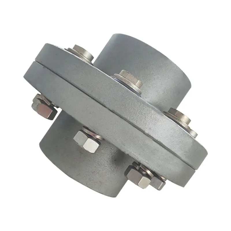
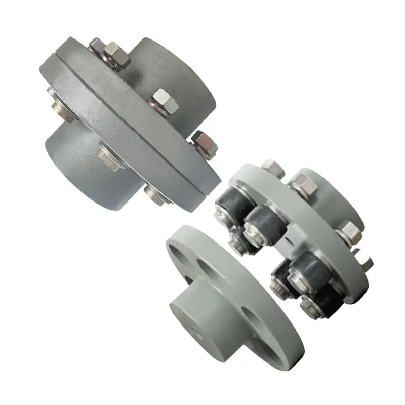
China OEM Rigid Stainless Steel Grooved Fitting Couplings Ruixuan Manufacture dc coupling
Product Description
Product Description
Steel flexible joint is also called clamp, open expansion joint, steel flexible pipe joint. Steel flexible joint is a kind of pipe connection, reliable performance, easy to install products. At low pressure, by the elastic deformation of the sealing ring, to achieve the purpose of sealing; When the pressure increases, the medium acts on the sealing ring to play the role of self-sealing, and there is a gap between the pipe ends to compensate for the displacement and deflection of the pipe caused by thermal expansion and cold contraction.
The working temperature of the clamp joint is generally -30ºC-+130ºC. The medium property is weak acid, weak alkali and lubricating oil range can be applied. If beyond the above range can also provide our company with the nature of the medium parameters or optional parameters or optional specified rubber ring material. In addition to the connection function, the joint can also provide compensation, withstand axial force, provide Angle, reduce vibration wave, adapt to the change of foundation.
The advantages of clamp joint:
1 Clamp joint has good continuity, will not produce distortion, easy to achieve the ideal laying state.
2 Clamp pipe joint in a free state, do not bear the weight of the pipe, not subjected to external shear, especially DN200 pipe diameter, more must consider the weight of the pipe.
3. It is easy to keep the coaxial position when installing the clamp joint to ensure the uneven distribution of the radial clearance between the inner diameter of the pipe clamp and the outer diameter of the pipe. The rubber ring will be deformed under high pressure due to the large local clearance, which will affect the sealing effect and even destroy the rubber ring.
4. It is suitable for the application in the subsidence zone, which can reduce the Angle between the pipe segments caused by the subsidence of the support pier.
5 is conducive to pipeline maintenance. Turn the pipe, save labor and effort when changing the pipe.
Detailed Photos
Product Parameters
PN1.6/2.5/4.0/6.4MPa KRHD
| DN(mm) | Dw(mm) | Allowable Angle Φ |
Installation length L (mm) |
Maximal length (mm) |
Fitting bolt d×L (mm) |
| 80 | 89 | 17.90 | 100 | 110 | M12*60 |
| 100 | 108 | 15.06 | 100 | 110 | M14*60 |
| 125 | 133 | 13.05 | 105 | 115 | M14*60 |
| 150 | 159 | 12.09 | 110 | 120 | M14*60 |
| 175 | 194 | 10.51 | 110 | 120 | M16*60 |
| 200 | 219 | 9.33 | 116 | 126 | M16*75 |
| 225 | 245 | 8.36 | 122 | 132 | M16*80 |
| 250 | 273 | 7.51 | 127 | 137 | M18*90 |
| 300 | 325 | 6.32 | 130 | 140 | M18*100 |
| 350 | 377 | 5.45 | 135 | 145 | M18*100 |
| 400 | 426 | 4.80 | 140 | 150 | M18*110 |
| 450 | 480 | 4.28 | 145 | 155 | M18*110 |
| 500 | 530 | 3.88 | 150 | 160 | M18*120 |
| 600 | 630 | 3.27 | 155 | 165 | M18*120 |
| 700 | 720 | 2.86 | 160 | 170 | M20*120 |
| 800 | 820 | 2.51 | 165 | 175 | M20*130 |
| 900 | 920 | 2.24 | 170 | 180 | M20*130 |
| 1000 | 1571 | 2.02 | 175 | 185 | M20*130 |
| 1200 | 1220 | 1.69 | 180 | 190 | M22*140 |
| 1400 | 1420 | 1.45 | 185 | 195 | M22*140 |
| 1600 | 1620 | 1.27 | 190 | 200 | M22*140 |
| 1800 | 1820 | 1.13 | 195 | 205 | M22*150 |
| 2000 | 2571 | 1.01 | 200 | 210 | M24*150 |
| 2200 | 2571 | 1.01 | 205 | 215 | M24*150 |
| 2400 | 2420 | 1.01 | 210 | 220 | M24*150 |
| 2600 | 2620 | 1.01 | 215 | 225 | M24*160 |
| 2800 | 2830 | 1.01 | 220 | 230 | M27*160 |
| 3000 | 3571 | 1.01 | 225 | 230 | M27*160 |
| 3200 | 3220 | 1.01 | 230 | 240 | M27*180 |
Datas above are only for reference,if you want to know more details, please click here to contact us.
Installation Instructions
1. Prepare groove pipe sections, fittings and accessories that meet the requirements.
2. Check whether the rubber sealing ring is damaged and put it on the end of a steel pipe.
3. There should be a certain gap between the end and both ends of the steel pipe close to the end and both ends of the pipe which has been covered with rubber sealing ring. The clearance shall meet the standard requirements.
4. Put the rubber seal ring on the end of another steel pipe, make the rubber seal ring in the middle of the interface, and apply lubricant on the same side.
5. Check the axis of the pipe.
6. Install upper and lower clamps on the outer side of rubber seal-ing ring at the interface position, and clip the collar convex edge into the groove.
7. Press the upper and lower clamp ears with hand force, tighten the collar of the clamp with a wooden hammer, and tighten the upper and lower clamps tightly.
8. At the clamp screw hole position, put on the studs and tighten the nuts evenly to prevent the rubber sealing ring from wrin-kling.
9. check and comfirm that the collar convex edge is clamped into the groove.
products application
Company Profile
HangZhou Ruixuan pipeline equipment factory was founded in 1996.It is an excellent enterprise specializing in manufacturing and selling pipe fittings.It’s located in Xicun village ,HangZhou city,ZheJiang province ,the concentrated area of pipeline equipment industry in China.The company factory is located in Xicun town pipeline equipment industrial park.It covered an area of20000 square meters.
At present, the company has the production capacity of pipeline equipment with a maximum diameter of 4000mm, and its main products are: Steel expansion joint, flexible waterproof sleeve, large diameter flange, double flange force transfer expansion joint, large deflection loose sleeve compensation joint, spherical compensation joint, sleeve compensator, bellows compensator, non-metallic compensator, rubber expansion joint, DC medium no thrust sleeve compensator, flexible expansion pipe and other pipeline equipment. The annual production capacity is 30 million sets.
The flexible telescopic pipe equipment is mainly used in the pipeline crossing different geological structures under different conditions and the application of pipe installation drop, reduce or avoid the impact of geological settlement and crustal activity on the pipeline, so that the construction unit can save more than 50% of the cost when purchasing the equipment. The rubber expansion joint series products of the company, the maximum production diameter of 3600mm, have been applied in millions of units of thermal power projects in China for many times, and have been praised by the users.
The company passed ISO9001:2008 quality management system certification in 2009 and ISO14000:2004 environmental management system certification in 2009. The company has a strict quality control system, standard production process, standard factory inspection hand section, to ensure that every product meets the national standards and customer requirements.
Business philosophy: responsible production of products, return the trust of customers; To build a community with a sense of belonging and appreciate employees’ contributions; Make a contribution to the society of enterprises, give back to the good times. HangZhou Ruixuan pipeline equipment factory is willing to work with friends from all walks of life hand in hand, mutual support, create a better future!
Certifications
FAQ
Q:Can you make the product as per client’s requirement?
A:Yes, we can make it with your exact requirement.
Q:What are your payment terms?
A:T/T (30% as deposit, the rest 70% will be paid before delivery), L/C at sight.
Q:Where is your nearest loading port?
A:ZheJiang , HangZhou or ZheJiang , China.
Q:How can you guarantee the quality or any warranty?
A:If any quality problems during use, all the products can be returned or according to consumer’s requests.
Q:Do you accept small quantity order?
A:Of course we do.
Q:And what is your shipment and delivery time?
A:By sea or air. Normally 7 to 14 Days for delivery, according to your order quantity.
|
Shipping Cost:
Estimated freight per unit. |
To be negotiated |
|---|
| Application: | Fire Fighting |
|---|---|
| Feature: | Corrosion Resistant |
| Material: | Ductile Iron |
| Samples: |
US$ 6.5/Piece
1 Piece(Min.Order) | Order Sample |
|---|
| Customization: |
Available
| Customized Request |
|---|

What Is a Coupling?
A coupling is a device used to connect two shafts. It transmits power between them and allows for some misalignment or end movement. There are several types of couplings. The most common ones are gear couplings and planetary couplings. However, there are many others as well.
Transfer of energy
Energy coupling is a process by which two biological reactions are linked by sharing energy. The energy released during one reaction can be used to drive the second. It is a very useful mechanism that synchronizes two biological systems. All cells have two types of reactions, exergonic and endergonic, and they are connected through energy coupling.
This process is important for a number of reasons. The first is that it allows the exchange of electrons and their energy. In a single molecule, this energy transfer involves the exchange of two electrons of different energy and spin. This exchange occurs because of the overlap interaction of two MOs.
Secondly, it is possible to achieve quadratic coupling. This is a phenomenon that occurs in circular membrane resonators when the system is statically deflected. This phenomenon has been gaining a great deal of interest as a mechanism for stronger coupling. If this mechanism is employed in a physical system, energy can be transferred on a nanometer scale.
The magnetic field is another important factor that affects the exchange of energy between semiconductor QWs. A strong magnetic field controls the strength of the coupling and the energy order of the exciton. The magnetic field can also influence the direction of polariton-mediated energy transfer. This mechanism is very promising for controlling the routing of excitation in a semiconductor.
Functions
Couplings play a variety of functions, including transferring power, compensating for misalignment, and absorbing shock. These functions depend on the type of shaft being coupled. There are four basic types: angular, parallel, and symmetrical. In many cases, coupling is necessary to accommodate misalignment.
Couplings are mechanical devices that join two rotating pieces of equipment. They are used to transfer power and allow for a small degree of end-to-end misalignment. This allows them to be used in many different applications, such as the transmission from the gearbox to the differential in an automobile. In addition, couplings can be used to transfer power to spindles.
Types
There are two main types of couplings: rigid and flexible. Rigid couplings are designed to prevent relative motion between the two shafts and are suitable for applications where precise alignment is required. However, high stresses in the case of significant misalignment can cause early failure of the coupling. Flexible couplings, on the other hand, allow for misalignment and allow for torque transmission.
A software application may exhibit different types of coupling. The first type involves the use of data. This means that one module may use data from another module for its operation. A good example of data coupling is the inheritance of an object. In a software application, one module can use another module’s data and parameters.
Another type of coupling is a rigid sleeve coupling. This type of coupling has a pipe with a bore that is finished to a specified tolerance. The pipe contains two threaded holes for transmitting torque. The sleeve is secured by a gib head key. This type of coupling may be used in applications where a couple of shafts are close together.
Other types of coupling include common and external. Common coupling occurs when two modules share global data and communication protocols. This type of coupling can lead to uncontrollable error propagation and unforeseen side effects when changes are made to the system. External coupling, on the other hand, involves two modules sharing an external device interface or communication protocol. Both types of coupling involve a shared code structure and depend on the external modules or hardware.
Mechanical couplings are essential in power transmission. They connect rotating shafts and can either be rigid or flexible, depending on the accuracy required. These couplings are used in pumps, compressors, motors, and generators to transmit power and torque. In addition to transferring power, couplings can also prevent torque overload.
Applications
Different coupling styles are ideal for different applications, and they have different characteristics that influence the coupling’s reliability during operation. These characteristics include stiffness, misalignment capability, ease of installation and maintenance, inherent balance, and speed capability. Selecting the right coupling style for a particular application is essential to minimize performance problems and maximize utility.
It is important to know the requirements for the coupling you choose before you start shopping. A proper selection process takes into account several design criteria, including torque and rpm, acoustic signals, and environmental factors. Once you’ve identified these parameters, you can select the best coupling for the job.
A gear coupling provides a mechanical connection between two rotating shafts. These couplings use gear mesh to transmit torque and power between two shafts. They’re typically used on large industrial machines, but they can also be used in smaller motion control systems. In smaller systems, a zero-backlash coupling design is ideal.
Another type of coupling is the flange coupling. These are easy to manufacture. Their design is similar to a sleeve coupling. But unlike a sleeve coupling, a flange coupling features a keyway on one side and two threaded holes on the other. These couplings are used in medium-duty industrial applications.
Besides being useful for power transmission, couplings can also prevent machine vibration. If vibration occurs in a machine, it can cause it to deviate from its predetermined position, or damage the motor. Couplings, however, help prevent this by absorbing the vibration and shock and preventing damage to expensive parts.
Couplings are heavily used in the industrial machinery and electrical industries. They provide the necessary rotation mechanism required by machinery and other equipment. Coupling suppliers can help customers find the right coupling for a specific application.
Criteria for selecting a coupling
When selecting a coupling for a specific application, there are a number of different factors to consider. These factors vary greatly, as do operating conditions, so selecting the best coupling for your system can be challenging. Some of these factors include horsepower, torque, and speed. You also need to consider the size of the shafts and the geometry of the equipment. Space restrictions and maintenance and installation requirements should also be taken into account. Other considerations can be specific to your system, such as the need for reversing.
First, determine what size coupling you need. The coupling’s size should be able to handle the torque required by the application. In addition, determine the interface connection, such as straight or tapered keyed shafts. Some couplings also feature integral flange connections.
During the specification process, be sure to specify which materials the coupling will be made of. This is important because the material will dictate most of its performance characteristics. Most couplings are made of stainless steel or aluminum, but you can also find ones made of Delrin, titanium, or other engineering-grade materials.
One of the most important factors to consider when selecting a coupling is its torque capability. If the torque rating is not adequate, the coupling can be damaged or break easily. Torque is a major factor in coupling selection, but it is often underestimated. In order to ensure maximum coupling performance, you should also take into consideration the size of the shafts and hubs.
In some cases, a coupling will need lubrication throughout its lifecycle. It may need to be lubricated every six months or even once a year. But there are couplings available that require no lubrication at all. An RBI flexible coupling by CZPT is one such example. Using a coupling of this kind can immediately cut down your total cost of ownership.
editor by CX 2023-08-02