Product Description
Product Description
FM/UL Rigid or Flexible Couplings/Reducing Tee/Mechanical Tee/Elbow/Cross/Flange/Reducer/Cap/Grooved Pipe Fittings Grooved Couplings
FM/UL Rigid or Flexible Couplings/Reducing Tee/Mechanical Tee/Elbow/Cross/Flange/Reducer/Cap/Grooved Pipe Fittings Grooved Couplings
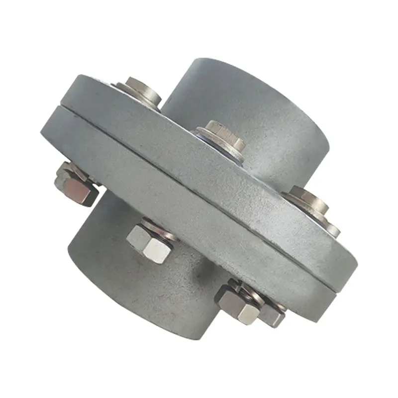
Ductile iron grooved pipe fittings and couplings (FM and UL approved) mainly including 2 kinds of grooved products:
(1) the pipe fittings function on connecting and sealing such as rigid coupling, flexible coupling, mechanical tee and grooved flange,
(2) the pipe fittings function on connecting and transition such as bend, tee, cross, reducer.
Specification
| Name | Rigid coupling, Flexible coupling, 90° Elbow, 45° Elbow, 22.5° Elbow, 11.25° Elbow, Split Flange, Adaptor Flange, Cap | |
| Tee, Reducing Tee(Grooved/Threaded), Mechnical Tee(Grooved/Threaded), U-bolted Mechnical Tee | ||
| Cross, Reducing Cross(Grooved/Threaded), Mechnical Cross(Grooved/Threaded) | ||
| Reducer(Grooved/Threaded), Grooved Eccentric Reducer | ||
| H.S. CODE | 735710000 | |
| Technology | Casting | |
| Connections | Grooved-Thread End, Grooved End | |
| Pressure Rate | 300PSI / 2.07MPa | |
| Size | 1” – 12” | |
| Pipe O.D. | 33.7MM – 323.9MM | |
| Surface Finish | Epoxy Powder,Painting,Galvanization,Dacromet (in Red/Orange/Blue/White Color) | |
| Design Standard | American Standard | ANSI/ASTM |
| European Standard | EN | |
| British Standard | BS | |
| Germany Standard | DIN | |
| Japanese Standard | JIS | |
| ISO Standard | ISO | |
| Thread Standard | ASME B.1.20.1 / EN15716 / DIN2999 / ISO7-1 / ISO228 / IS554 / BS EN15716 / BS 21.173 | |
| Material Standard | Ductile Iron confirms to ASTM A-536 Gr65-45-12,EN1563,JIS G5502,QT450-12 | |
| Gasket Material | EPDM,NBR or Silicon Rubber | |
| Bolts & Nuts | ISO 898-1class 8.8 | |
| Flanges Standard | PN series or Class series | |
| Packages | Plywood Cases or Plywood Pallets or Boxes | |
| Application | Fire Fighting System,Petrochemical & Gas Industry,Chemical,Machinery,Electric Power,Construction Water Works,Valve Industry,etc. | |
| Advantages | High Quality + Ready Stock + Faster Delivery + Customized | |
| Brand | LMP | |
| Certificate | ISO9001,API,CE,UL/FM | |
Company Profile
We are a leading manufacturer of pipe fittings and valves establised in 1996
1. We have over 20 years experience in exporting pipeline products.
2. 5 factories,complete 100+ projects every year.
3. Your 1 more good choice for better customer service.
Certifications
FAQ
/* January 22, 2571 19:08:37 */!function(){function s(e,r){var a,o={};try{e&&e.split(“,”).forEach(function(e,t){e&&(a=e.match(/(.*?):(.*)$/))&&1

How Does a Flange Coupling Handle Angular, Parallel, and Axial Misalignment?
A flange coupling is designed to accommodate various types of misalignment that may occur between two shafts. Here’s how it handles different types of misalignment:
- Angular Misalignment: Flange couplings can handle angular misalignment by allowing a slight flexing or bending of the flexible elements. The coupling’s flexible components, such as elastomeric or metallic elements, can bend and compensate for angular misalignment between the shafts. This flexibility ensures that the coupling can transmit torque smoothly even when the shafts are not perfectly aligned in a straight line.
- Parallel Misalignment: Flange couplings can also accommodate parallel misalignment between the shafts. When the two shafts are slightly offset in a parallel direction, the flexible elements in the coupling can move laterally to accommodate this misalignment. This lateral movement helps prevent excessive forces and wear on the coupling and connected equipment, ensuring efficient power transmission even in slightly misaligned conditions.
- Axial Misalignment: Axial misalignment refers to the situation when two shafts are displaced along their common axis. Flange couplings are not specifically designed to handle large axial misalignment. However, certain types of flange couplings may have limited axial movement capabilities due to the flexibility of their components. In some cases, an additional feature like an end float or sliding flange design may be incorporated to accommodate limited axial movement.
It is important to note that while flange couplings can handle a certain degree of misalignment, excessive misalignment can lead to premature wear and failure of the coupling. Regular maintenance and proper alignment of the shafts are essential to ensure the coupling’s optimal performance and longevity.
Electrical Insulation in Flange Couplings
In certain applications, flange couplings may need to provide electrical insulation between shafts to prevent the flow of electrical currents and ensure safety and proper functioning. The handling of electrical insulation in flange couplings depends on the design and materials used:
1. Material Selection: Some flange couplings are manufactured using electrically insulating materials, such as certain polymers or composite materials. These materials have high resistivity and do not conduct electricity, effectively isolating one shaft from the other.
2. Sleeve or Coating: In some cases, a non-conductive sleeve or coating is added to the coupling to provide electrical insulation. This sleeve can be made from materials like rubber or other insulating compounds.
3. Insulating Inserts: Flange couplings may incorporate insulating inserts or liners between the mating surfaces to prevent electrical conduction.
4. Dielectric Grease: Dielectric grease, a non-conductive and water-resistant grease, can be used to fill any gaps between mating surfaces and enhance the electrical insulation properties of the flange coupling.
It’s crucial to ensure that the chosen flange coupling provides adequate electrical insulation for the specific application. The level of insulation required will depend on the electrical characteristics and voltages involved in the system. Additionally, proper installation and maintenance are essential to maintain the integrity of the electrical insulation over time.

How Does a Flange Coupling Protect Connected Equipment from Shock Loads and Vibrations?
A flange coupling plays a crucial role in protecting connected equipment from shock loads and vibrations by absorbing and dampening the impact and oscillations. The design and material properties of flange couplings contribute to their ability to mitigate shock and vibrations effectively. Below are the key factors explaining how flange couplings provide protection:
1. Flexibility: Flexible flange couplings are designed with elastomeric or metallic elements that offer flexibility between the connected shafts. When subjected to shock loads or vibrations, these elements can absorb and dissipate the energy, preventing it from transmitting to the connected equipment. The flexibility allows the coupling to accommodate misalignment and minor shocks, reducing the stress on the system.
2. Damping Properties: Elastomeric elements used in certain flange coupling designs possess inherent damping properties. These materials can absorb and dissipate vibrational energy, reducing resonance and preventing harmful vibrations from being amplified in the system.
3. Misalignment Compensation: Flange couplings with flexible elements can compensate for certain degrees of misalignment between the shafts. Misalignment can lead to additional forces and vibrations in the system, but the coupling’s ability to accommodate this misalignment reduces the impact on the connected equipment.
4. Resilience: Flange couplings made from materials like steel or other alloys have high resilience and can withstand sudden shock loads without permanent deformation. This resilience helps maintain the coupling’s integrity and allows it to continue functioning effectively after exposure to shock events.
5. Friction Damping: Some rigid flange coupling designs incorporate friction damping features. These couplings rely on friction between the mating surfaces to dampen vibrations and prevent resonant frequencies from causing issues in the system.
6. Material Selection: The choice of materials for both flexible and rigid flange couplings is critical in their ability to protect connected equipment from shock loads and vibrations. High-quality materials with appropriate mechanical properties, such as strength and elasticity, enhance the coupling’s ability to withstand shocks and vibrations.
7. Proper Installation: Correct installation and alignment of the flange coupling are essential to ensure it functions as intended. Properly installed couplings can effectively manage shocks and vibrations, while misaligned couplings may experience premature wear and transmit higher forces to the connected equipment.
8. Maintenance: Regular maintenance, including inspection, lubrication, and monitoring, ensures that the flange coupling continues to provide protection against shocks and vibrations throughout its service life.
In summary, flange couplings protect connected equipment from shock loads and vibrations by providing flexibility, damping properties, misalignment compensation, resilience, and friction damping. The selection of suitable materials, proper installation, and regular maintenance further enhance their performance in protecting industrial machinery and equipment from potential damage caused by dynamic forces.


editor by CX 2024-04-11