Product Description
Product Details
| General Products Application/Service Area | Metal Parts Solution for Vehicle, Agriculture machine, Construction Machine, transportation equipment, Valve and Pump system. E.g. Engine bracket, truck chassis bracket, gear box , gear housing , gear cover, shaft, spline shaft , pulley, flange, connection pipe, pipe, hydraulic valve , valve housing ,Fitting , flange, wheel, flywheel, oil pump housing, starter housing, coolant pump housing, transmission shaft , transmission gear, sprocket, chains etc. |
| Process for Casting Iron | Sand Casting , Resin Sand Casting, Green Sand Casting, Shell Molding, Automatic Molding, |
| Casting Tolerance | CT9-10 for Machine Molding Process, CT8-9 for Shell Molding and Lost Foam Molding Casting Process CT10-11 for Manual Molding Sand casting Process |
| Applicable Material | Ductile Iron, Grey Iron Casting, or as customer request. |
| Applicable Finish Surface Treatment | Shot/sand blast, polishing, Powder coating, ED- Coating, etc |
Product Show
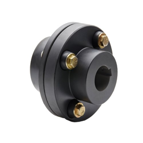
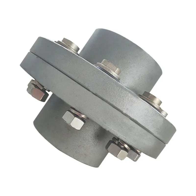
Flange Couplings for Motor-to-Shaft and Shaft-to-Shaft Connections
Flange couplings are versatile components that can be used for both motor-to-shaft and shaft-to-shaft connections in a wide range of mechanical systems. Their design and features make them suitable for various applications:
1. Motor-to-Shaft Connections: Flange couplings are commonly used to connect electric motors to driven equipment, such as pumps, fans, compressors, and conveyors. In motor-to-shaft connections, the flange coupling is mounted on the motor shaft and connected to the input shaft of the driven equipment. This configuration ensures efficient power transmission from the motor to the driven component.
2. Shaft-to-Shaft Connections: Flange couplings are also employed for shaft-to-shaft connections, where two shafts need to be linked together. This could involve connecting two separate pieces of machinery or extending the length of an existing shaft. Flange couplings allow for the secure and precise alignment of the two shafts, ensuring smooth rotation and power transmission between them.
Flange couplings are available in various designs, such as rigid flange couplings, flexible flange couplings, and floating shaft couplings. Rigid flange couplings offer a more rigid connection, ideal for applications where shaft misalignment is minimal. Flexible flange couplings, on the other hand, can accommodate some degree of misalignment and provide vibration dampening, making them suitable for systems with dynamic conditions or slight misalignments.
When selecting a flange coupling for a specific connection, factors such as the required torque capacity, shaft sizes, misalignment tolerance, and operating conditions need to be considered. Proper installation and alignment are crucial to ensure the optimal performance and longevity of the flange coupling in both motor-to-shaft and shaft-to-shaft connections.
In summary, flange couplings are versatile components that can be effectively used for both motor-to-shaft and shaft-to-shaft connections. Their ability to provide secure and efficient power transmission makes them a valuable choice in various industries and mechanical systems.

How Does a Flange Coupling Help in Power Transmission Efficiency?
A flange coupling plays a crucial role in improving power transmission efficiency in mechanical systems. It efficiently transfers power from one shaft to another while maintaining the alignment and minimizing energy losses. Here’s how flange couplings contribute to power transmission efficiency:
1. Direct Power Transfer: Flange couplings provide a direct connection between the driving and driven shafts, ensuring a solid and reliable power transfer without the need for intermediate components. This direct coupling minimizes power losses that can occur in systems with multiple components and connections.
2. Rigid and Precise Connection: Rigid flange couplings offer a precise and firm connection between shafts, minimizing angular and parallel misalignments. By reducing misalignment, energy losses due to friction and vibrations are minimized, leading to more efficient power transmission.
3. Absence of Slippage: Flange couplings are designed to provide a secure and non-slip connection between shafts. Unlike some other coupling types that might experience slippage under heavy loads or during acceleration, flange couplings maintain constant power transmission without loss of torque.
4. High Load-Carrying Capacity: Flange couplings are capable of handling high torque and axial loads, making them suitable for heavy-duty applications. The ability to handle these loads without deformation ensures efficient power transmission even in demanding industrial settings.
5. Minimal Maintenance: Flange couplings are generally low-maintenance components. Once properly installed, they require minimal attention, reducing downtime and enhancing overall system efficiency.
6. Balancing and Vibration Damping: Some flange coupling designs, such as flexible and torsionally flexible couplings, provide additional benefits like vibration damping and torsional flexibility. These features help to absorb shocks and vibrations, ensuring a smoother power transmission and protecting connected equipment from damage.
7. Selection of Appropriate Flange Type: Choosing the right type of flange coupling for a specific application is crucial for optimal power transmission efficiency. Different flange designs offer varying levels of flexibility and alignment capabilities, allowing engineers to select the most suitable coupling based on the system requirements.
In summary, flange couplings facilitate efficient power transmission by maintaining alignment, reducing energy losses, and providing a robust and reliable connection between shafts. Properly selected and installed flange couplings help improve the overall efficiency and performance of mechanical systems.

What are the Maintenance Requirements for Flange Couplings?
Flange couplings require regular maintenance to ensure optimal performance and longevity. Proper maintenance can help prevent unexpected failures and downtime in the machinery or equipment. Here are the key maintenance requirements for flange couplings:
1. Inspection: Regularly inspect the flange coupling for signs of wear, damage, or misalignment. Check for cracks, corrosion, or any deformations in the flange and bolt holes. Ensure that the coupling is properly aligned with the shafts.2. Lubrication: Lubricate the flange coupling as per the manufacturer’s recommendations. Proper lubrication helps reduce friction and wear between the mating surfaces of the flanges, bolts, and nuts. Use the right type of lubricant that is compatible with the coupling material.3. Bolt Torque Check: Check the bolt torque regularly to ensure that the flange coupling is securely fastened. Loose bolts can lead to misalignment and coupling failure. Follow the recommended torque values provided by the manufacturer.4. Alignment: Maintain proper shaft alignment to prevent excessive forces on the flange coupling. Misalignment can cause uneven load distribution and accelerated wear on the coupling components.5. Environmental Protection: If the flange coupling is exposed to harsh or corrosive environments, take necessary measures to protect it. Consider using protective coatings or seals to prevent corrosion and damage.6. Regular Servicing: Schedule regular servicing of the machinery or equipment, including the flange coupling. This allows for a thorough inspection and timely replacement of worn-out or damaged components.7. Replacement of Worn Parts: When signs of wear or damage are detected during inspections, replace the worn or damaged parts promptly. Delaying the replacement can lead to further damage and compromise the performance of the coupling.8. Follow Manufacturer’s Guidelines: Always follow the maintenance guidelines provided by the flange coupling manufacturer. They may have specific recommendations based on the design and material of the coupling. Proper maintenance and regular checks can extend the life of the flange coupling and contribute to the overall reliability and efficiency of the connected machinery. It is essential to create a maintenance schedule and adhere to it diligently to ensure the smooth operation of the flange coupling and the entire mechanical system.


editor by CX 2023-08-18
China high quality Universal Flange Adaptor Flexible Coupling for Di AC Steel PVC HDPE Pipe flange coupling
Product Description
Dismantling Joints are designed to provide a simple method of installation and removal of flanged pipeline components such as valves, pumps and strainers from a pipeline. Dismantling Joints allow a variable setting distance of 50mm on site and are supplied complete, ready to be installed. Dismantling Joints are restrained products that prevent axial pipe movement, they are most suited to valve and pump chambers, and complex steel fitting installations.
PRODUCT DESCRIPTION:
Body: ductile iron grade 500-7/450-12 in accordance with ISO 1083 .
Bolts:carbon steel with zinc coating/stainless steel CZPT customers’ request.
Gasket :EPDM/NBR/SBR
Size and Pressure
Size:DN50-DN2000 Pressure:PN10 PN16 PN25 PN40
Coating
External coatings
zinc coating+biHangZhou coating
liquid epoxy painting
epoxy applied by FBE
according to customers’ requirements
Internal coatings
cement mortar lining
liquid epoxy painting
epoxy applied by FBE
according to customers’ requirements
Package
Bubble bags , cartons or wookden case for free options.
Use
The ductile iron dismantling joint is a pipe expansion joint than could reduce vibration and noise greatly , which is widely used in pipeline system to solve pipe interface axial stretching displacement .
Our machining shop located in HangZhou, using the latest CNC equipment to provide our customer with high quality products.
Horizontal and Vertical Machining Center
CNC lathe and normal lathe
CNC drilling and milling Center
Other assistant equipment
Test Equipment
We use first-class facilities in the world to control all the processes to offer products with the best component quality and the correct dimension.Customer’s satisfaction is our final target!
Our test equipment include :Three dimentional machine,inspection gauge,Metallurgical structure analysis,Direct reading spectrometer,Tensile testing machine,Inside micrometer,Geneal gauge.
| Standard | ISO 2531 & BS EN 545 & EN 598 |
| Material | GGG40 & GGG50 & other ductile iron |
| Package | Wooden pallet & Wooden case &As request |
| Accessories | Gasket, Bolt & Nut available CZPT request |
| Payment | 30%in advance by TT,balance before loading |
| Coating | Fusion bonded epoxy coating ; Cement CZPT inside and zinc primer and biHangZhou painting outside ; BiHangZhou painting inside and outside ; Red anti-rustcoating |
What Industries Commonly Use Flange Couplings for Power Transmission?
Flange couplings are widely used in various industries for power transmission due to their reliability and versatility. Some of the common industries where flange couplings are employed include:
1. Manufacturing: In manufacturing industries such as automotive, aerospace, electronics, and consumer goods, flange couplings are utilized in machinery and equipment to transmit power between different components.
2. Oil and Gas: The oil and gas industry often uses flange couplings in pumps, compressors, and turbines for power transmission in exploration, extraction, and refining processes.
3. Chemical and Petrochemical: Flange couplings are used in various equipment within the chemical and petrochemical industry, including mixers, agitators, and pumps, to transfer power efficiently.
4. Mining and Construction: Heavy-duty machinery in mining and construction applications relies on flange couplings to transmit power in demanding and challenging environments.
5. Power Generation: Power plants, including thermal, hydroelectric, and wind power facilities, use flange couplings in turbines, generators, and auxiliary systems for power transmission.
6. Marine: In the marine industry, flange couplings are utilized in propulsion systems, winches, and other equipment that requires power transmission in marine vessels.
7. Steel and Metal Processing: Steel mills and metal processing plants use flange couplings in various equipment, including rolling mills and conveyor systems.
8. Food and Beverage: The food processing and beverage industry use flange couplings in mixers, pumps, and conveyor systems to handle power transmission in hygienic environments.
9. Pharmaceutical: Pharmaceutical manufacturing equipment employs flange couplings for power transmission in processes such as mixing, granulation, and tablet compression.
10. Water and Wastewater: Flange couplings are used in water treatment plants and wastewater facilities to transfer power in pumps and other equipment.
These are just a few examples, and flange couplings are found in many other industries where reliable power transmission is essential for smooth operations.
Can Flange Couplings Be Used in Heavy-Duty Applications Such as Mining and Construction?
Yes, flange couplings can be used in heavy-duty applications such as mining and construction, where they are often employed to transmit power between large machinery and equipment. Flange couplings are designed to handle high torque and axial loads, making them suitable for these demanding industries. Here are some reasons why flange couplings are well-suited for heavy-duty applications:
1. High Load Capacity: Flange couplings are engineered to provide high load-carrying capacity, making them ideal for heavy machinery used in mining and construction. They can efficiently transfer power between components with large torque requirements, such as conveyors, crushers, and excavators.
2. Tolerance to Misalignment: Heavy-duty equipment may experience misalignment due to uneven loading, vibrations, or other factors. Flange couplings can accommodate certain degrees of misalignment, reducing stress on connected components and preventing premature wear or failure.
3. Durability and Strength: In mining and construction, equipment is subjected to harsh conditions, impacts, and vibrations. Flange couplings are typically made from robust materials like steel or cast iron, providing exceptional strength and durability to withstand the rugged environments encountered in these industries.
4. Easy Maintenance: While heavy-duty applications may expose equipment to extreme conditions, maintenance and downtime should be minimized. Flange couplings are designed to be relatively easy to install and maintain, ensuring that machinery can quickly get back to work after routine maintenance or repairs.
5. Various Flange Designs: Flange couplings come in different designs, including rigid, flexible, and torsionally flexible variations. This allows engineers to select the most appropriate type for the specific needs of mining and construction equipment.
However, it is crucial to consider factors such as the specific load requirements, operating conditions, and alignment precision when choosing flange couplings for heavy-duty applications. Proper installation, regular inspection, and adherence to recommended maintenance schedules are essential to ensure the reliable performance and extended service life of the flange couplings in mining and construction equipment.

What is a flange coupling and how does it work?
A flange coupling is a type of rigid coupling used to connect two shafts together in a mechanical system. It consists of two flanges, one on each shaft, which are bolted together to form a solid and robust connection. Flange couplings are widely used in applications where precise alignment, high torque transmission, and zero backlash are critical.
The key components of a flange coupling include:
- Flanges: The flanges are circular discs with holes around the perimeter for bolting them to the respective shaft ends. The flanges are made from materials such as steel, cast iron, or aluminum, depending on the application requirements.
- Fasteners: High-strength bolts or studs with nuts are used to fasten the flanges together securely. The number and size of the bolts depend on the size and torque capacity of the coupling.
- Gaskets: In some cases, gaskets or spacers are used between the flanges to provide insulation, prevent corrosion, or compensate for any slight misalignments between the shafts.
How a flange coupling works:
- The two shafts that need to be connected are brought together with their respective flanges facing each other.
- The flanges are aligned precisely to ensure that both shafts are in perfect axial alignment. Proper alignment is essential to prevent excessive loads on the bearings and to ensure efficient torque transmission.
- Once the flanges are aligned, high-strength bolts or studs are inserted through the holes in the flanges, and nuts are fastened tightly to hold the flanges together securely.
- The tight connection between the flanges creates a rigid joint between the shafts, allowing torque to be transmitted from one shaft to the other with minimal losses.
- Flange couplings are designed to have zero backlash, meaning there is no play or free movement between the shafts when the direction of rotation changes. This feature ensures precise and immediate power transmission between the connected shafts.
Flange couplings are commonly used in various industrial applications, including heavy machinery, pumps, compressors, and marine propulsion systems. They are preferred when a reliable, high-torque transmission with precise alignment is required. However, they do not offer flexibility to accommodate misalignment, which is a limitation compared to flexible couplings. Therefore, proper alignment during installation is critical to avoid premature wear and failure of the coupling and connected equipment.
editor by CX 2023-08-15
China wholesaler ISO2531 Ductile Iron Flange Adaptor Flexible Coupling Flange Adaptor Coupling flange coupling
Product Description
Ductile Iron flange adapter with PN10/16 coupling for Ductile Iron Pipe fitting
The flange adapter transmits the pressure and thrust of the connected parts (blind plate force) and compensates the pipeline error, so as to reduce the damage of the axial thrust to the pipeline and pipeline equipment. It is mainly used for loose sleeve connection of pump, valve, pipeline and other accessories.
Specifications
Body: Ductile iron
Bolts: Galvanized steel / Stainless steel
Seal gasket: EPDM
Coating: CZPT Epoxy
Class: PN10/16, 125/150Lbs
Size:DN50-DN600
|
Size |
DN50-DN300 |
|
Standard |
ISO2531/EN545/EN598/AWWA |
|
Pressure |
PN10/PN16/PN25 |
|
Material |
Ductile Iron GGG50 material with FBE coated |
|
Coating |
Fusion bonded epoxy coating(250 micron) |
|
Color |
Blue FBE / Epoxy Coating |
|
Connection Type |
Flange Joint |
|
Gasket |
EPDM, SBR/NBR also available |
|
bolt nut |
Steel 8.8 zinced/Dacro |
Our Factory
HangZhou Fluido Import and Export Co.,Ltd. is a professional flange, pipe fittings,valves and ductile iron pipe fitting manufacturer and exporter for water treatment, construction, petrochemical and oilfield industry. We deliver exceptional value by providing customers with the most important elements : Premium Quality, Reasonable Price and Impeccable Services.
Our products adhere to GB, JIS, DIN, DIN, EN, API, ANSI/ASME specifications for material content, pressure ratings and quality assurance, ensuring that our customers receive consistent quality and reliability every time. Additionally, we are able to modify existing products or manufacture new designs to meet specific requirements.
We have been known as a company who always keeps our promise of quality products, reasonable pricing, and prompt delivery. By providing a broad range of high quality products at competitive prices, We see ourselves not just as a supplier for our clients, but as their partner in helping them achieved their own goals and objectives.
Package as customized
Certifications
Other Related Product
Our Services
1. Many years experience in manufacturing and exporting fittings
2. Experienced technical staff
3. Marking the customer’s brand on the product surface directly
4. All fittings are approved by CE and ISO
5. Supply OEM service
6. Small orders accepted
7. Competitive prices, top quality, professional service and prompt delivery
8. Quality checking and controlling strictly
FAQ
Q:When can I get the quotation?
A:We usually quote within 12 hours after we get your inquiry.If you are very urgent to get the price,pls call us or tell us in your email so that we will regard your inquiry priority.
Q: Could I get samples?
A: Yes,we have materials in stock to help you to get the samples as soon as we can.
Q:Can you do the design for us?
A:We have a professional team having rich experience in manufacturing.We could supply customized size,grade of material,and the coating.We also could supply the package according to your request.
Q.How are orders packed and shipped ?
A: For custom order, we can design full-color custom packaging to match your brand, if requires. Most shipments include boxes packed inside an outer carton and placed on a wooden pallet.
Q:What abount the lead time for mass production?
A:Honestly,it depends on the order quantity and your specific requirements of products.
Q.What are your quality control procedures?
A: We adhere to strict quality control procedures that begin with product design and carry through to the end of the production process using state-of -the-art quality control equipment.

Factors to Consider When Choosing a Flange Coupling for a Specific System
When selecting a flange coupling for a specific system, several factors need to be taken into consideration to ensure optimal performance and reliability. Here are the key factors to consider:
- 1. Load and Torque Requirements: Determine the maximum load and torque that the flange coupling will experience in the application. This includes both static and dynamic loads. Select a flange coupling that can handle these loads without exceeding its rated capacity.
- 2. Shaft Diameter: Measure the diameter of the shafts that will be connected by the flange coupling. Ensure that the coupling’s bore size matches the shaft diameter to provide a proper fit and secure connection.
- 3. Misalignment Tolerance: Consider the amount of misalignment that the system may experience during operation. Flange couplings are available in different designs, and some can accommodate higher levels of misalignment than others. Choose a coupling that can handle the expected misalignment to prevent premature wear and stress on the system.
- 4. Operating Speed: Determine the rotational speed of the connected equipment. High-speed applications may require precision balancing and careful selection of materials to prevent issues like resonance and excessive vibration.
- 5. Environmental Conditions: Consider the environmental factors the flange coupling will be exposed to, such as temperature, humidity, dust, and chemicals. Choose a material and coating that can withstand the specific environmental conditions to prevent corrosion and degradation.
- 6. Space Limitations: Evaluate the available space for installing the flange coupling. Some applications may have limited space for coupling installation, requiring compact designs or custom solutions.
- 7. Serviceability: Assess the ease of installation and maintenance of the flange coupling. A coupling that is easy to install and service can reduce downtime and maintenance costs.
- 8. Compatibility: Ensure that the flange coupling is compatible with the equipment and shafts in the system. Consider factors such as keyways, set screws, and other connection methods.
- 9. Material Selection: Choose the appropriate material for the flange coupling based on factors like load, temperature, and corrosion resistance. Common materials include steel, stainless steel, aluminum, and various alloys.
- 10. Cost: Compare the cost of different flange coupling options, considering both the initial investment and long-term maintenance expenses. Balance the cost with the desired performance and reliability.
It is essential to consult with coupling manufacturers or industry experts to ensure the flange coupling’s suitability for the specific application. Properly selecting and installing the right flange coupling can contribute to the efficiency, reliability, and longevity of the connected machinery and system.

Common Installation Mistakes to Avoid When Using Flange Couplings
Proper installation is crucial for the efficient and reliable operation of flange couplings. Avoiding common installation mistakes can help ensure the longevity and optimal performance of the coupling. Here are some common installation mistakes to avoid:
1. Improper Alignment: One of the most critical aspects of flange coupling installation is ensuring proper shaft alignment. Misalignment can lead to increased wear, vibrations, and decreased power transmission efficiency. Always use precision alignment tools and techniques to achieve accurate alignment.
2. Over-Tightening: Over-tightening the coupling’s bolts can cause excessive stresses on the coupling and connected equipment. It may lead to premature failure or deformation of the coupling. Follow the manufacturer’s recommended torque values for tightening the bolts.
3. Under-Tightening: On the other hand, under-tightening the bolts may result in a loose connection, leading to misalignment and potential damage to the coupling during operation. Make sure to achieve the proper torque during installation.
4. Lack of Lubrication: Insufficient or improper lubrication of the coupling’s components can result in increased friction and wear. Follow the manufacturer’s guidelines for lubrication, and use the recommended lubricant to ensure smooth operation.
5. Contamination: Avoid introducing dirt, debris, or foreign particles into the coupling during installation. Contaminants can lead to wear and damage over time, reducing the coupling’s performance.
6. Incorrect Coupling Selection: Choosing the wrong type or size of flange coupling for the application can lead to performance issues. Consider factors like torque, speed, load, and operating environment when selecting the coupling.
7. Lack of Inspection: After installation, regularly inspect the flange coupling and its components for signs of wear, damage, or misalignment. Early detection of issues allows for timely maintenance and prevents potential system failures.
8. Ignoring Manufacturer Guidelines: Always follow the manufacturer’s installation instructions and guidelines. Each flange coupling may have specific requirements and recommendations that must be adhered to for proper functioning.
9. Incorrect Shaft Fit: Ensure that the coupling properly fits the shafts’ dimensions. A loose fit can cause slippage, while a tight fit can lead to stress concentration and premature failure.
10. Inadequate Inspection of Components: Before installation, inspect all coupling components, including flanges, bolts, and keyways, for any defects or damage. Replace any damaged parts before installation.
By avoiding these common installation mistakes, you can maximize the performance and lifespan of flange couplings in your mechanical systems.
What is a flange coupling and how does it work?
A flange coupling is a type of rigid coupling used to connect two shafts together in a mechanical system. It consists of two flanges, one on each shaft, which are bolted together to form a solid and robust connection. Flange couplings are widely used in applications where precise alignment, high torque transmission, and zero backlash are critical.
The key components of a flange coupling include:
- Flanges: The flanges are circular discs with holes around the perimeter for bolting them to the respective shaft ends. The flanges are made from materials such as steel, cast iron, or aluminum, depending on the application requirements.
- Fasteners: High-strength bolts or studs with nuts are used to fasten the flanges together securely. The number and size of the bolts depend on the size and torque capacity of the coupling.
- Gaskets: In some cases, gaskets or spacers are used between the flanges to provide insulation, prevent corrosion, or compensate for any slight misalignments between the shafts.
How a flange coupling works:
- The two shafts that need to be connected are brought together with their respective flanges facing each other.
- The flanges are aligned precisely to ensure that both shafts are in perfect axial alignment. Proper alignment is essential to prevent excessive loads on the bearings and to ensure efficient torque transmission.
- Once the flanges are aligned, high-strength bolts or studs are inserted through the holes in the flanges, and nuts are fastened tightly to hold the flanges together securely.
- The tight connection between the flanges creates a rigid joint between the shafts, allowing torque to be transmitted from one shaft to the other with minimal losses.
- Flange couplings are designed to have zero backlash, meaning there is no play or free movement between the shafts when the direction of rotation changes. This feature ensures precise and immediate power transmission between the connected shafts.
Flange couplings are commonly used in various industrial applications, including heavy machinery, pumps, compressors, and marine propulsion systems. They are preferred when a reliable, high-torque transmission with precise alignment is required. However, they do not offer flexibility to accommodate misalignment, which is a limitation compared to flexible couplings. Therefore, proper alignment during installation is critical to avoid premature wear and failure of the coupling and connected equipment.
editor by CX 2023-08-14
China best CZPT HRC Flexible Rubber Coupling HRC130 with B, F and H Flange for Transmissiom Machine flange coupling
Product Description
Product Description
We are the leading top Chinese coupling manufacturer, and are specializing in various high quality HRC coupling.
KASIN HRC Shaft Couplings
1. Material:the hub of the Couplings is Cast Iron,the Elastomer is Rubbe
2. OEM and ODM are available
3. High efficient in transmission
4. Finishing:The surface treatment is normally Phosphated and painting
5. High quality with competitive price
6. Different models suitable for your different demands
7. Stock for different bore size on both sides available.
8. Application in wide range of environment.
9. Quick and easy mounting and disassembly.
10. Resistant to oil and electrical insulation.
11. Identical clockwise and anticlockwise rotational characteristics.
12. Small dimension, low weight, high transmitted torque.
13. It has good performance on compensating the misalignment.
14.Feature of couplings:free of maintenance,simple structure and easy to install.
15.Application:Mainly used in the mining, metallurgical, cement, chemicals, construction, building materials, electric power, telecommunications, textiles, and transportation departments.
Techncial Date
Related Products
Roller Chain Coupling FCL Coupling Curved Jaw Coupling
Manufacturing
Applications:
NM couplings are offered in the industry’s largest variety of stock bore/keyway combinations. These couplings require no lubrication and provide highly reliable service for light, medium, and heavy duty electrical motor and internal combustion power transmission applications. Applications include power transmission to industrial equipment such as pumps, gear boxes, compressors, blowers, mixers, and conveyors.
About Us
Kasin group was established in 1989, and its first product is casting carrier trolley for power & free conveyor system. In 1995, CZPT purchased HangZhou Guoping Forging Factory (LYGP), a marketer of forging bolts & nuts to power & free line market in china. With this acquisition, CZPT positioned itself as 1 of major parts suppliers of monorail and power & free conveyor system in china.
In 2/8822 0571 -57152031 Fax: 86~/8822 0571 -57152030
Http://kasinchain
Flange Couplings for Motor-to-Shaft and Shaft-to-Shaft Connections
Flange couplings are versatile components that can be used for both motor-to-shaft and shaft-to-shaft connections in a wide range of mechanical systems. Their design and features make them suitable for various applications:
1. Motor-to-Shaft Connections: Flange couplings are commonly used to connect electric motors to driven equipment, such as pumps, fans, compressors, and conveyors. In motor-to-shaft connections, the flange coupling is mounted on the motor shaft and connected to the input shaft of the driven equipment. This configuration ensures efficient power transmission from the motor to the driven component.
2. Shaft-to-Shaft Connections: Flange couplings are also employed for shaft-to-shaft connections, where two shafts need to be linked together. This could involve connecting two separate pieces of machinery or extending the length of an existing shaft. Flange couplings allow for the secure and precise alignment of the two shafts, ensuring smooth rotation and power transmission between them.
Flange couplings are available in various designs, such as rigid flange couplings, flexible flange couplings, and floating shaft couplings. Rigid flange couplings offer a more rigid connection, ideal for applications where shaft misalignment is minimal. Flexible flange couplings, on the other hand, can accommodate some degree of misalignment and provide vibration dampening, making them suitable for systems with dynamic conditions or slight misalignments.
When selecting a flange coupling for a specific connection, factors such as the required torque capacity, shaft sizes, misalignment tolerance, and operating conditions need to be considered. Proper installation and alignment are crucial to ensure the optimal performance and longevity of the flange coupling in both motor-to-shaft and shaft-to-shaft connections.
In summary, flange couplings are versatile components that can be effectively used for both motor-to-shaft and shaft-to-shaft connections. Their ability to provide secure and efficient power transmission makes them a valuable choice in various industries and mechanical systems.

How do Flange Couplings Handle Shaft Misalignment in Rotating Equipment?
Flange couplings are designed to handle certain degrees of shaft misalignment in rotating equipment. The flexibility of flange couplings allows them to accommodate minor misalignments between the connected shafts without causing significant stress or damage. The ability to handle shaft misalignment is one of the key advantages of using flange couplings in various industrial applications. Here’s how flange couplings handle shaft misalignment:
1. Radial Misalignment: Flange couplings can handle radial misalignment, which is the offset between the rotational axis of two connected shafts. This misalignment can be in the form of parallel misalignment or angular misalignment. Flange couplings with flexible elements, such as elastomeric inserts or diaphragms, can absorb and compensate for radial misalignment, ensuring smooth power transmission between the shafts.
2. Axial Misalignment: Axial misalignment occurs when there is a linear displacement along the rotational axis of the shafts. While some flange couplings may have limited axial misalignment capabilities, others may not be designed to accommodate significant axial movements. Engineers must consider the specific requirements of the application to ensure that the selected flange coupling can handle the anticipated axial misalignment.
3. Angular Misalignment: Angular misalignment refers to the angle between the rotational axes of the two shafts. Flange couplings with flexible elements can handle a certain degree of angular misalignment by flexing and adjusting to the changing angle. However, excessive angular misalignment can lead to increased wear and reduced coupling life, so it’s essential to keep the misalignment within acceptable limits.
4. Rigid Couplings vs. Flexible Couplings: Rigid couplings, such as sleeve couplings or clamp-style couplings, are not capable of handling misalignment and require precise alignment during installation. On the other hand, flexible flange couplings can tolerate misalignment, making them more forgiving and easier to install in applications where perfect alignment is challenging to achieve.
It is important to note that while flange couplings can handle certain degrees of misalignment, excessive or sustained misalignment can lead to premature wear, reduced coupling life, and potential equipment damage. Therefore, proper alignment during installation and regular maintenance checks are essential to ensure the optimal performance and longevity of flange couplings in rotating equipment.

Materials Used in Manufacturing Flange Couplings
Flange couplings are manufactured using various materials, each offering specific properties and advantages. The choice of material depends on factors such as application requirements, environmental conditions, and cost considerations. Here are some commonly used materials in manufacturing flange couplings:
- 1. Steel: Steel is one of the most common materials for flange couplings. It offers excellent strength, durability, and resistance to wear. Steel couplings are suitable for a wide range of applications and can handle high torque and heavy loads.
- 2. Stainless Steel: Stainless steel is chosen for its superior corrosion resistance, making it ideal for applications where the coupling is exposed to moisture, chemicals, or aggressive substances. Stainless steel flange couplings are common in industries such as food processing, pharmaceuticals, and marine.
- 3. Cast Iron: Cast iron couplings are known for their excellent strength and vibration-damping characteristics. They are often used in industrial settings, including pumps, compressors, and conveyor systems.
- 4. Aluminum: Aluminum couplings are lightweight and suitable for applications where weight is a concern. They are commonly used in industries such as aerospace and automotive.
- 5. Brass: Brass couplings offer good corrosion resistance and electrical conductivity. They are used in specific applications that require these properties.
- 6. Bronze: Bronze couplings are valued for their high strength, corrosion resistance, and resistance to wear. They are commonly used in marine and heavy machinery applications.
- 7. Plastic: Plastic couplings, such as nylon or polyurethane, are used in applications where weight, non-conductivity, and chemical resistance are critical factors.
- 8. Composite Materials: Some modern flange couplings may use composite materials that combine different properties, such as strength, flexibility, and corrosion resistance.
When selecting the material for a flange coupling, it is essential to consider factors such as load capacity, temperature range, chemical exposure, and the specific demands of the application. Proper material selection ensures that the flange coupling performs optimally and has a long service life in its intended environment.
editor by CX 2023-08-10
China Professional Flange Cast Iron Coupling Steel Universal Joint Cardan Pump Rubber Motor Disc Curved Tooth Flex Rigid Drive Shaft Nm Yox Fluid Jaw Flexible Chain Gear Couplings flange coupling
Product Description
Excellent powder metallurgy parts metallic sintered parts
We could offer various powder metallurgy parts including iron based and copper based with top quality and cheapest price, please only send the drawing or sample to us, we will according to customer’s requirement to make it. if you are interested in our product, please do not hesitate to contact us, we would like to offer the top quality and best service for you. thank you!
How do We Work with Our Clients
1. For a design expert or a big company with your own engineering team: we prefer to receive a fully RFQ pack from you including drawing, 3D model, quantity, pictures;
2. For a start-up company owner or green hand for engineering: just send an idea that you want to try, you don’t even need to know what casting is;
3. Our sales will reply you within 24 hours to confirm further details and give the estimated quote time;
4. Our engineering team will evaluate your inquiry and provide our offer within next 1~3 working days.
5. We can arrange a technical communication meeting with you and our engineers together anytime if required.
| Place of origin: | Jangsu,China |
| Type: | Powder metallurgy sintering |
| Spare parts type: | Powder metallurgy parts |
| Machinery Test report: | Provided |
| Material: | Iron,stainless,steel,copper |
| Key selling points: | Quality assurance |
| Mould type: | Tungsten steel |
| Material standard: | MPIF 35,DIN 3571,JIS Z 2550 |
| Application: | Small home appliances,Lockset,Electric tool, automobile, |
| Brand Name: | OEM SERVICE |
| Plating: | Customized |
| After-sales Service: | Online support |
| Processing: | Powder Metallurgr,CNC Machining |
| Powder Metallurgr: | High frequency quenching, oil immersion |
| Quality Control: | 100% inspection |
The Advantage of Powder Metallurgy Process
1. Cost effective
The final products can be compacted with powder metallurgy method ,and no need or can shorten the processing of machine .It can save material greatly and reduce the production cost .
2. Complex shapes
Powder metallurgy allows to obtain complex shapes directly from the compacting tooling ,without any machining operation ,like teeth ,splines ,profiles ,frontal geometries etc.
3. High precision
Achievable tolerances in the perpendicular direction of compacting are typically IT 8-9 as sintered,improvable up to IT 5-7 after sizing .Additional machining operations can improve the precision .
4. Self-lubrication
The interconnected porosity of the material can be filled with oils ,obtaining then a self-lubricating bearing :the oil provides constant lubrication between bearing and shaft ,and the system does not need any additional external lubricant .
5. Green technology
The manufacturing process of sintered components is certified as ecological ,because the material waste is very low ,the product is recyclable ,and the energy efficiency is good because the material is not molten.
FAQ
Q1: What is the type of payment?
A: Usually you should prepay 50% of the total amount. The balance should be pay off before shipment.
Q2: How to guarantee the high quality?
A: 100% inspection. We have Carl Zeiss high-precision testing equipment and testing department to make sure every product of size,appearance and pressure test are good.
Q3: How long will you give me the reply?
A: we will contact you in 12 hours as soon as we can.
Q4. How about your delivery time?
A: Generally, it will take 25 to 35 days after receiving your advance payment. The specific delivery time depends on the items and the quantity of your order. and if the item was non standard, we have to consider extra 10-15days for tooling/mould made.
Q5. Can you produce according to the samples or drawings?
A: Yes, we can produce by your samples or technical drawings. We can build the molds and fixtures.
Q6: How about tooling Charge?
A: Tooling charge only charge once when first order, all future orders would not charge again even tooling repair or under maintance.
Q7: What is your sample policy?
A: We can supply the sample if we have ready parts in stock, but the customers have to pay the sample cost and the courier cost.
Q8: How do you make our business long-term and good relationship?
A: 1. We keep good quality and competitive price to ensure our customers benefit ;
2. We respect every customer as our friend and we sincerely do business and make friends with them, no matter where they come from.
Torque and Speed Ratings of Flange Couplings
Flange couplings are available in various sizes and designs to accommodate a wide range of torque and rotational speed requirements. The torque and speed ratings of flange couplings depend on several factors, including their size, material, and design.
Torque Rating:
The torque rating of a flange coupling indicates the maximum amount of torque it can transmit without experiencing failure or damage. It is typically specified in Nm (Newton-meters) or lb-ft (pound-feet). The torque rating varies for different sizes and types of flange couplings. Larger flange couplings generally have higher torque ratings compared to smaller ones.
Speed Rating:
The speed rating of a flange coupling represents the maximum rotational speed at which it can operate reliably without excessive vibration or wear. It is typically expressed in RPM (revolutions per minute). The speed rating is influenced by factors such as the design, material, and balancing of the flange coupling. Higher-speed applications require flange couplings that can handle the increased centrifugal forces and dynamic loads associated with higher RPMs.
Size and Type:
The torque and speed ratings vary for different sizes and types of flange couplings. For example:
- Smaller flange couplings, such as those used in light-duty applications, may have torque ratings ranging from a few Nm to several hundred Nm, and speed ratings up to a few thousand RPM.
- Larger flange couplings, used in heavy-duty industrial applications, can have torque ratings exceeding several thousand Nm and speed ratings that may reach tens of thousands of RPM.
- Flexible flange couplings may have slightly lower torque ratings compared to rigid flange couplings but offer greater misalignment compensation.
Manufacturer Specifications:
It is essential to refer to the manufacturer’s specifications and technical data to determine the specific torque and speed ratings for each size and type of flange coupling. Manufacturers typically provide detailed performance data to help users select the appropriate flange coupling for their specific application.
Application Considerations:
When selecting a flange coupling, it is crucial to consider the torque and speed requirements of the application. The operating conditions, such as load fluctuations and thermal effects, should also be taken into account to ensure the flange coupling’s reliable performance and longevity.
Conclusion:
Flange couplings come in various sizes and designs, each with its own torque and speed ratings. Properly selecting a flange coupling that meets the specific torque and speed requirements of the application is essential to ensure efficient and trouble-free power transmission in mechanical systems.

Key Features to Consider When Purchasing a Flange Coupling
When purchasing a flange coupling, it is essential to consider several key features to ensure it meets the specific requirements of your application. Here are the main factors to look for:
- Type of Flange Coupling: There are various types of flange couplings, such as rigid, flexible, and fluid couplings. Choose the type that best suits your application’s needs, considering factors like misalignment compensation, torsional stiffness, and vibration damping.
- Size and Dimensions: Select the flange coupling with the appropriate size and dimensions to fit your shafts and equipment. Consider shaft diameter, coupling length, and any space limitations.
- Material: Flange couplings can be made from various materials, including steel, aluminum, stainless steel, and elastomers. Choose a material that offers the required strength, corrosion resistance, and durability for your operating conditions.
- Torsional Rating: Check the torsional rating of the flange coupling to ensure it can handle the torque requirements of your application without failure or deformation.
- Misalignment Compensation: If your application experiences shaft misalignment, opt for a flexible flange coupling that can accommodate angular, parallel, and axial misalignment to prevent stress on connected equipment.
- Backlash: For precision applications, select a flange coupling with minimal or no backlash to maintain accurate positioning and reduce the effects of mechanical play.
- Operating Speed: Consider the operating speed range of the flange coupling to ensure it can handle the rotational speed requirements without issues like resonance or fatigue.
- Environmental Compatibility: Evaluate the flange coupling’s ability to withstand the environmental conditions of your application, such as temperature, humidity, and exposure to chemicals or corrosive substances.
- Installation and Maintenance: Choose a flange coupling that is easy to install and maintain, as proper installation and periodic maintenance are crucial for optimal performance and longevity.
- Cost and Value: Compare the cost of the flange coupling with its features and performance to ensure you are getting the best value for your investment.
By carefully considering these key features, you can select a flange coupling that not only meets the demands of your application but also ensures reliable and efficient power transmission while minimizing downtime and maintenance costs.
What is a flange coupling and how does it work?
A flange coupling is a type of rigid coupling used to connect two shafts together in a mechanical system. It consists of two flanges, one on each shaft, which are bolted together to form a solid and robust connection. Flange couplings are widely used in applications where precise alignment, high torque transmission, and zero backlash are critical.
The key components of a flange coupling include:
- Flanges: The flanges are circular discs with holes around the perimeter for bolting them to the respective shaft ends. The flanges are made from materials such as steel, cast iron, or aluminum, depending on the application requirements.
- Fasteners: High-strength bolts or studs with nuts are used to fasten the flanges together securely. The number and size of the bolts depend on the size and torque capacity of the coupling.
- Gaskets: In some cases, gaskets or spacers are used between the flanges to provide insulation, prevent corrosion, or compensate for any slight misalignments between the shafts.
How a flange coupling works:
- The two shafts that need to be connected are brought together with their respective flanges facing each other.
- The flanges are aligned precisely to ensure that both shafts are in perfect axial alignment. Proper alignment is essential to prevent excessive loads on the bearings and to ensure efficient torque transmission.
- Once the flanges are aligned, high-strength bolts or studs are inserted through the holes in the flanges, and nuts are fastened tightly to hold the flanges together securely.
- The tight connection between the flanges creates a rigid joint between the shafts, allowing torque to be transmitted from one shaft to the other with minimal losses.
- Flange couplings are designed to have zero backlash, meaning there is no play or free movement between the shafts when the direction of rotation changes. This feature ensures precise and immediate power transmission between the connected shafts.
Flange couplings are commonly used in various industrial applications, including heavy machinery, pumps, compressors, and marine propulsion systems. They are preferred when a reliable, high-torque transmission with precise alignment is required. However, they do not offer flexibility to accommodate misalignment, which is a limitation compared to flexible couplings. Therefore, proper alignment during installation is critical to avoid premature wear and failure of the coupling and connected equipment.
editor by CX 2023-08-02
China 16AS 15576 Flexible Coupling LB-Q2023 coefficient of coupling
Warranty: 3months
Applicable Industries: Production Plant, Equipment Mend Stores, Retail, Design operates
Customized assistance: ODM
Structure: Common
Flexible or Rigid: Rigid
Common or Nonstandard: Regular, Regular
Content: Metal
Description: Coupling
Model: 16AS
Dimension: one hundred fifty five*76
LEBON No.: LB-Q2571
Application: Excavator
Guarantee Time: Extended Guarantee Interval
Characteristic: 100% New
Package deal: regular expart carton deal
Supply Time: If stock,1-2 days after receive the payment
Packaging Specifics: Common export carton bundle
Port: HangZhou
16AS one hundred fifty five*76 Adaptable Coupling LB-Q2571
one. Coupling2. Design: 16AS3. CZPT No.:LB-Q25714. Dimension: a hundred and fifty five*seventy six
Sample Chamber
Common Introduction:
We are 1 of the biggest specialist mechanical development enterprises in China which was recognized in nineteen nineties. Our organization is specializing in production and exporting the complete variety of Excavator Elements, these kinds of as all varieties of Filters(Sunfield),Alternators, custom made created spiral bevel equipment higher functionality bevel equipment set Starters, Drinking water Pumps, Cylinder Blocks, Oil Coolers, Oil Separators , Stepping Motors, Pistons & Piston Rings, cnc machining rack pinion gear nylon plastic equipment rack for robotic Liners, Ignition Switches, Camshafts, Crankshafts, Main & Con Rod Bearings, Solenoid Valves, Stopper Solenoids, Worm Gear Velocity Reducer For Electrical Motor Equipment Pumps, Enthusiast Blades and Thermostats which are utilised as replacement of a lot of type of devices.
Advantages:one.Competitive price2.Higher top quality guaranteed3.Specializing in exporting for a lot more than 10 years4.Good deal
Principal Markets:Southeast Asian Countries, Middle East, South The us, North Europe, Arica, and many others.
Payment and Shipping
Make contact with us
If you are interested in our merchandise, pls do not be reluctant to make contact with us now! worm equipment assemblies gerber equipment Higher top quality module .8 small mini spur gears We will offer you the best items with very best services!

Programming With Couplings
A coupling is a mechanical device that connects two shafts together and transmits power. Its purpose is to join rotating equipment and allows some degree of end-movement or misalignment. There are many different types of couplings. It’s important to choose the right one for your application.
Mechanical connection between two shafts
There are many ways to achieve mechanical connection between two shafts, including the use of a coupling. One common type is the beam coupling, which is also known as a helical coupling. It is used for transmission of torque between two shafts. This type of connection accommodates axial, parallel and angular misalignments.
The hubs and shafts of a worm gear are connected together by a coupling. This mechanical connection allows one shaft to turn another without causing a mechanical failure. This type of coupling is made from sliding or rubbing parts to transfer torque. However, the coupling is not designed to withstand jerks, so it isn’t suitable for high-speed applications.
The use of a coupling is common in machinery and equipment. It helps transmit power from one drive shaft to the other, while adding mechanical flexibility. It is also useful for reducing the impact and vibration caused by misalignment. It also protects the drive shaft components from wear and tear.
A double-hook coupling can be used to provide a uniform angular velocity at the driven shaft. Another example is a double-jointed coupling. A double-jointed coupling can be used to connect shafts that are not directly intersecting. The double-jointed yoke can be used for the same purpose.
A shaft coupling is a device that maintains a strong mechanical connection between two shafts. It transfers motion from one shaft to another, at all loads and misalignments. Unlike a conventional linkage, a shaft coupling isn’t designed to allow relative motion between the two shafts. Couplings often serve several purposes in a machine, but their primary use is torque and power transmission.
Functions that control the flow of another function
One of the simplest programming constructs is a function that controls the flow of another function. A function can take an argument and return a different value, but it must be ready to return before it can pass that value to another function. To do this, you can use the goto statement and the if statement. Another way to control flow is to use a conditional statement.
Criteria for selecting a coupling
There are several important factors to consider when choosing the right coupling. One of the most important factors is coupling stiffness, which depends on the material used and the shape. The stiffness of a coupling determines its ability to resist elastic deformation. A stiff coupling is desirable for certain types of applications, but it’s undesirable for others. Stiffness can reduce the performance of a system if there’s too much inertia. To avoid this, ensure that the coupling you choose is within the recommended limits.
The size of a coupling is also important. Different coupling types can accommodate different shaft sizes and shapes. Some couplings have special features, such as braking and shear pin protection. When choosing a coupling, you should also consider the type of driven equipment. If you need to connect a high-torque motor, for example, you’ll want to choose a gear coupling. Likewise, a high-speed machine may require a disc coupling.
Another factor to consider when selecting a coupling is the torque rating. Despite its importance, it’s often underestimated. The torque rating is defined as the torque of the coupling divided by its OD. In some cases, torque may fluctuate during a cycle, requiring a coupling with a higher torque rating.
Torsionally flexible couplings are also important to consider. Their design should be able to withstand the torque required during operation, as well as the required speed. The coupling should also have a high degree of torsional stiffness, as well as damping. Furthermore, a damping coupling can reduce the energy wasted through vibration.
The sizing of a coupling is also determined by the torque. Many engineers use torque to select the correct coupling size, but they also take into consideration torsional flexibility and torsional stiffness. For example, a shaft may be able to handle large torque without damaging the coupling, while a disk may be unable to handle large amounts of torque.
Besides torque, another important consideration in coupling selection is the cost. While a coupling may be cheaper, it may be less reliable or easier to maintain. Couplings that are difficult to service may not last as long. They may also require frequent maintenance. If that’s the case, consider purchasing a coupling with a low service factor.
There are many different types of couplings. Some require additional lubrication throughout their lifetime, while others are 100% lubrication-free. An example of a 100% lubrication-free coupling is the RBI flexible coupling from CZPT. This type of coupling can significantly reduce your total cost of ownership.
In addition to the above-mentioned benefits, elastomeric couplings are low-cost and need little maintenance. While they are often cheaper than metallic couplings, they also have excellent shock absorption and vibration dampening properties. However, they are susceptible to high temperatures. Also, they are difficult to balance as an assembly, and have limited overload torque capacity.
editor by CX 2023-06-28
China high quality Factory Nonstandard Flexible Woodon China Jaw L 050 Universal Joint Coupling SWC100 SWC120 SWC150 SWC180 SWC200 SWC225 SWC250 coupling definition
Product Description
| Product Name | Cardan Shaft |
| Product Model | SWC-I75A-335+40 |
| Main Material | 35CrMo or 45# Steel |
| Nominal Torque | 500 N.M |
| Normal Length | 335 mm |
| Length Compensation | 40 mm |
| Standard Or Nonstandard: | Nonstandard |
|---|---|
| Shaft Hole: | 19-32 |
| Torque: | >80N.M |
| Bore Diameter: | 19mm |
| Speed: | 4000r/M |
| Structure: | Flexible |
| Samples: |
US$ 10/Piece
1 Piece(Min.Order) | |
|---|

Types of Coupling
A coupling is a device used to join two shafts together and transmit power. Its primary function is to join rotating equipment and allows for some end movement and misalignment. This article discusses different types of coupling, including Magnetic coupling and Shaft coupling. This article also includes information on Overload safety mechanical coupling.
Flexible beam coupling
Flexible beam couplings are universal joints that can deal with shafts that are offset or at an angle. They consist of a tube with couplings at both ends and a thin, flexible helix in the middle. This makes them suitable for use in a variety of applications, from motion control in robotics to attaching encoders to shafts.
These couplings are made of one-piece materials and are often made of stainless steel or aluminium alloy. However, they can also be made of acetal or titanium. While titanium and acetal are less common materials, they are still suitable for high-torque applications. For more information about beam couplings, contact CZPT Components.
Flexible beam couplings come in a variety of types and sizes. W series couplings are good for general purpose applications and are relatively economical. Stainless steel versions have increased torque capacity and torsional stiffness. Flexible beam couplings made of aluminum are ideal for servo and reverse motion. They are also available with metric dimensions.
Flexible beam couplings are made of aluminum alloy or stainless steel. Their patented slot pattern provides low bearing load and high torsional rigidity. They have a long operational life. They also require zero maintenance and can handle angular offset. Their advantages outweigh the disadvantages of traditional beam couplings.
Magnetic coupling
Magnetic coupling transfers torque from one shaft to another using a magnetic field. These couplings can be used on various types of machinery. These types of transmissions are very useful in many situations, especially when you need to move large amounts of weight. The magnetic field is also very effective at reducing friction between the two shafts, which can be extremely helpful if you’re moving heavy items or machinery.
Different magnetic couplings can transmit forces either linearly or rotated. Different magnetic couplings have different topologies and can be made to transmit force in various geometric configurations. Some of these types of couplings are based on different types of materials. For example, a ceramic magnetic material can be used for applications requiring high temperature resistance.
Hybrid couplings are also available. They have a hybrid design, which allows them to operate in either an asynchronous or synchronous mode. Hysterloy is an alloy that is easily magnetized and is used in synchronous couplings. A synchronous magnetic coupling produces a coupled magnetic circuit.
Magnetic coupling is a key factor in many physical processes. In a crystal, molecules exhibit different magnetic properties, depending on their atomic configuration. Consequently, different configurations produce different amounts of magnetic coupling. The type of magnetic coupling a molecule exhibits depends on the exchange parameter Kij. This exchange parameter is calculated by using quantum chemical methods.
Magnetic couplings are most commonly used in fluid transfer pump applications, where the drive shaft is hermetically separated from the fluid. Magnetic couplings also help prevent the transmission of vibration and axial or radial loads through the drive shaft. Moreover, they don’t require external power sources, since they use permanent magnets.
Shaft coupling
A shaft coupling is a mechanical device that connects two shafts. The coupling is designed to transmit full power from one shaft to the other, while keeping the shafts in perfect alignment. It should also reduce transmission of shock loads. Ideally, the coupling should be easy to connect and maintain alignment. It should also be free of projecting parts.
The shaft couplings that are used in machines are typically made of two types: universal coupling and CZPT coupling. CZPT couplings are designed to correct for lateral misalignment and are composed of two flanges with tongues and slots. They are usually fitted with pins. The T1 tongue is fitted into flange A, while the T2 tongue fits into flange B.
Another type of shaft coupling is known as a “sliced” coupling. This type of coupling compensates for inevitable shaft misalignments and provides high torque. Machined slits in the coupling’s outer shell help it achieve high torsional stiffness and excellent flexibility. The design allows for varying engagement angles, making it ideal for many different applications.
A shaft coupling is an important component of any machine. Proper alignment of the two shafts is vital to avoid machine breakdowns. If the shafts are misaligned, extra force can be placed on other parts of the machine, causing vibration, noise, and damage to the components. A good coupling should be easy to connect and should ensure precise alignment of the shaft. Ideally, it should also have no projecting parts.
Shaft couplings are designed to tolerate a certain amount of backlash, but it must be within a system’s threshold. Any angular movement of the shaft beyond this angle is considered excessive backlash. Excessive backlash results in excessive wear, stress, and breakage, and may also cause inaccurate alignment readings. It is therefore imperative to reduce backlash before the shaft alignment process.
Overload safety mechanical coupling
Overload safety mechanical couplings are devices that automatically disengage when the torque applied to them exceeds a specified limit. They are an efficient way to protect machinery and reduce the downtime associated with repairing damaged machinery. The advantage of overload couplings is their fast reaction time and ease of installation.
Overload safety mechanical couplings can be used in a wide range of applications. Their automatic coupling mechanisms can be used on any face or edge. In addition, they can be genderless, incorporating both male and female coupling features into a single mechanism. This means that they are both safe and gender-neutral.
Overload safety couplings protect rotating power transmission components from overloads. Overload protection devices are installed on electric motors to cut off power if the current exceeds a certain limit. Likewise, fluid couplings in conveyors are equipped with melting plug elements that allow the fluid to escape when the system becomes too hot. Mechanical force transmission devices, such as shear bolts, are designed with overload protection in mind.
A common design of an overload safety mechanical coupling consists of two or more arms and hubs separated by a plastic spider. Each coupling body has a set torque threshold. Exceeding this threshold may damage the spider or damage the jaws. In addition, the spider tends to dampen vibration and absorb axial extension. This coupling style is nearly backlash free, electrically isolating, and can tolerate very little parallel misalignment.
A mechanical coupling may also be a universal joint or jaw-clutch coupling. Its basic function is to connect the driver and driven shafts, and limits torque transfer. These devices are typically used in heavy-duty industries, such as steel plants and rolling mills. They also work well with industrial conveyor systems.
CZPT Pulley
The CZPT Pulley coupling family offers a comprehensive range of couplings for motors of all types. Not only does this range include standard motor couplings, but also servo couplings, which require ultra-precise control. CZPT Pulley couplings are also suitable for engine applications where high shocks and vibrations are encountered.
CZPT Pulley couplings have a “sliced” body structure, which allows for excellent torsional stiffness and strength. They are corrosion-resistant and can withstand high rotational speeds. The couplings’ design also ensures accurate shaft rotation while limiting shaft misalignment.
CZPT Pulley has introduced the CPU Pin Type couplings, which are effective at damping vibration and maintain zero backlash. They are also made from aluminum and are capable of absorbing heat. They come with recessed tightening screws. They can handle speeds up to 4,000 RPM, and are RoHS-compliant.
editor by CX 2023-05-26
China factory Low Price High Performance Compressor Special CZPT Gr75 Flexible Spider Shaft Coupling breakaway coupling
Product Description
Our company specializes in the research and development, manufacturing, distribution of mechanical equipment, to filter production lines as the focus, 18 years with a skilled, excellent after-sales service team.Has passed various quality certifications, always adhere to the principle of “quality is everything”, and always provide the best service for global customers. Our main compressor products are oil filters, oil separator filter and air filters, covering power plants, paper mills, petrochemical, textile, railway, cement, electronics and otherand all kinds of engineering machines filter industries. Most of our products are exported to the United States, East South Asia and Africa, which are 26 countries. We at Fluid Paradise are committed to providing filters at competitive prices, with superior quality and timely delivery. We sincerely hope to establish stable and strategic partnership with all countries in the world.
| Customized: | Non-Customized |
|---|---|
| Standard Component: | Standard Component |
| Material: | Copper |
| Category: | Solenoid Valve |
| Transport Package: | Cartons |
| Specification: | metal and plastic |
| Customization: |
Available
| Customized Request |
|---|
Types of Couplings
A coupling is a device that connects two shafts together. It transmits power from one end to another and is used for joining rotating equipment. A coupling is flexible and can accommodate a certain amount of end movement and misalignment. This allows for more flexibility in applications. Various types of couplings are available, and each one serves a specific purpose.
Shaft couplings
There are many types of shaft couplings, and they are used in a wide range of applications. The type you need depends on the torque, speed, and horsepower you need, as well as the size of the shaft and its spatial limitations. You may also need to consider whether the coupling will accommodate misalignment.
Some shaft couplings are flexible, while others are rigid. Flexible couplings can accommodate up to two degrees of misalignment. They are available in different materials, including aluminum, stainless steel, and titanium. They can also be known by different names, depending on the industry. Some couplings can also be used in a single or multiple-shaft application.
The first type of shaft coupling is a rigid coupling, which consists of two parts that fit together tightly around the shafts. These couplings are designed to have more flexibility than sleeved models, and they can be used on fixed shafts as well. The flanged coupling, on the other hand, is designed for heavy loads and is made of two perpendicular flanges. The flanges are large enough to accommodate screws and are generally used with heavy-duty applications.
CZPT shaft couplings are a great choice if you’re looking for a shaft coupling that delivers high performance, durability, and low cost. These metal disc-style couplings provide low backlash and high torsional stiffness. Their high misalignment tolerance reduces reaction loads on connected components, which makes them ideal for high-speed precision applications. Available in single and double-disc models, they have torque ratings of up to 2,200 in-lbs. (250N) and are available in fourteen sizes.
When using shaft couplings, it is important to choose the right type for your application. Backlash can cause a shaft coupling to break or become unusable. In order to prevent this from happening, you should replace worn or loose parts, and ensure that the hub and key are evenly positioned with the shaft. If you’re using a shaft coupling in a motion-control system, it is important to keep the torque level consistent.
Flexible couplings
Flexible couplings are a type of coupling used to connect two shafts. They are made of rubber or plastic and allow for axial movement of the connected equipment. They do not require lubrication and are resistant to fatigue failure. Flexible couplings are useful for a number of applications. A common type of flexible coupling is the gear coupling, which has gear teeth inside its sleeve. Another type of flexible coupling is the metallic membrane coupling. A metallic membrane coupling is flexible due to flexing metallic discs.
One major disadvantage of flexible couplings is their inability to fit certain types of pipe. This is because most couplings need to be stretched to fit the pipe. This problem is often the result of a change in pipe technology. Traditionally, drain and soil pipe is made of ductile iron or cast iron. Today, most pipes are made of PVC, which has a larger outside diameter than either cast or ductile iron. Because of these changes in pipe technology, many coupling manufacturers have not updated their mold sizing.
Flexible couplings can be either metallic, elastomeric, or a combination of the three. While there are some common characteristics of each type, you should always consider the tradeoffs of each type before choosing one. Generally, the most important considerations when selecting a flexible coupling are torque, misalignment, and ease of assembly and maintenance.
Flexible couplings are used in a wide range of industries. They are useful for connecting two pipes to ensure torque transfer. Although the types available are different, these are the most adaptable couplings in the market. They can withstand movement, vibration, and bending without causing any damage to the piping.
Clutch couplings
A clutch coupling connects two rotating shafts by friction. The clutch engages power when the engine is running, disengaging power when the brake is applied. Clutch couplings are used in applications where the speed of a machine is variable or where continuous service is required. The clutch can transmit power, torque, and axial force.
Clutch couplings come in a variety of styles and configurations. Some couplings are flexible, while others are rigid. Flexible couplings are available in a variety of materials, including stainless steel and aluminum. Some couplings also have a non-backlash design, which helps compensate for misalignment.
Clutch couplings may be synchronous or asynchronous. Synchronous couplings engage and disengage automatically when the driven machine exceeds its output speed. These couplings are synchronized by a synchronizing mechanism. When the output speed is exceeded, the synchronizing mechanism initiates the engagement process. The synchronizing mechanism does not engage or disengage when the output speed drops.
High speed clutches are available from a variety of manufacturers. Some manufacturers offer OEM assembly, repair services, and third-party logistics. These manufacturers serve the automotive, chemical, food, and wood industries, as well as the oilfield and material handling industries. Custom clutches can be manufactured for specific applications and can be fitted with additional features, such as precision machined teeth or keyway slots and grooves.
Couplings are available in PCE, C/T, and metric bores. Typically, the size of the input and output shafts will determine which type of coupling is needed. In addition, clutches may be configured for intermediate or high speeds, depending on the required torque.
Clamped couplings
Clamped couplings are commonly used in a variety of industries. They can be used in medical equipment, dental equipment, military equipment, laboratory equipment, and in precision industrial controls. They are available in a wide variety of sizes and keyways. This type of coupling offers a number of advantages, including ease of installation and quick and easy replacement.
A clamp coupling connects two parts by compressing them together. The clamping elements can be formed in a variety of ways, but they all have a gap between their surfaces. This friction squeezes the two parts together, much like pulling two rubber gloves apart. This type of coupling is also useful for joining two hoses or piping units.
Clamped couplings are designed with a single or double clamping shaft. The clamping parts are mounted in two halves and are held together by eight socket head cap screws. They offer high torque capacity and require little installation space. Their high rigidity ensures good positioning accuracy, making them ideal for dynamic drives. In addition, they are wear-free and offer simple radial assembly.
The invention relates to a method and system for clamping pipes to a tank vessel. This invention also relates to a method of loading and unloading tank vessels. The method can be used in oil production platforms and other platforms. A single point mooring method is also used in oil production platforms.
Clamped couplings can also be flexible. They can join two shafts together while allowing a small amount of end movement and misalignment. These couplings may also be used in the assembly of motors and gearboxes.
CZPT’s coupling
CZPT couplings are designed to be flexible, allowing them to accommodate misaligned shafts and transmit torque in either direction. They are made with three discs, two hubs, and a center that are arranged with grooves and fins. These features allow for two degrees of freedom during assembly, and can accommodate misalignment of up to 5% of the shaft diameter.
CZPT couplings have many uses. For example, they can be used to join two parallel coaxial rotating shafts. Their ability to transmit torque at the same rotation mechanism and speed makes them ideal for applications where electrical currents may be a problem. Because the couplings are not made of metal, they are electrically isolated. Designers should test their couplings during the prototype stage to ensure they are working properly.
The CZPT coupling consists of two hubs with one slot on each. An intermediate disk is located between the two hubs. The discs are used to reduce or prevent wear on other machine parts. CZPT couplings are inexpensive and easy to replace. They also have electrical insulation, which makes them easy to repair or replace.
CZPT couplings are a popular choice for stepper motor-driven positioning stages. The plastic center disc offers electrical isolation and absorbs shocks from frequent start/stops. These couplings are available in through-hub and blind-bore styles and can be installed in many applications.
CZPT couplings also allow for small degrees of shaft misalignment. This allows them to function in systems where shaft access is limited. They are easily removed without tools.
editor by CX 2023-05-16
China high quality ND Brand Chain Coupling Simplex Silent Duplex Roller Couplings Transmission Part Flexible Universal Stainless Steel Allows Simple Connection Disconnection Chain a fluid coupling
Product Description
Product Description
| Item | Chain coupling
The chain coupling, composed of two-strand chains and 2 sprockets, features simple and compact structure, and high flexibility, power transmission capability and durability. What’s more, the chain coupling allows simple connection/disconnection, and the use of the housing enhances safety and durability. |
| Material | Carbon steel,Brass,Stainless steel,etc |
| Tolerance | 0.01mm-0.02mm |
| Type number | 3012, 4012, 4014, 4016, 5014, 5016, 5018,6018, 6571, 6571, 8018, 8571, 1571, 12571 |
| Model | KC |
| Service | OEM,ODM,OBM |
Company Profile
In 2571, HangZhou CZPT Machinery Co.,ltd was established by Ms. Iris and her 2 partners(Mr. Tian and Mr. Yang) in HangZhou city(ZHangZhoug province, China), all 3 Founders are engineers who have more than averaged 30 years of experience. Then because the requirements of business expansion, in 2014, it moved to the current Xihu (West Lake) Dis. Industrial Zone (HangZhou city, ZHangZhoug province, China).
Through our CZPT brand ND, CZPT Machinery delivers agricultural solutions to agriculture machinery manufacturer and distributors CZPT through a full line of spiral bevel gearboxes, straight bevel gearboxes, spur gearboxes, drive shafts, sheet metal, hydraulic cylinder, motors, tyre, worm gearboxes, worm operators etc. Products can be customized as request.
We, CZPT machinery established a complete quality management system and sales service network to provide clients with high-quality products and satisfactory service. Our products are sold in 40 provinces and municipalities in China and 36 countries and regions in the world, our main market is the European market.
Our factory
Our sample room
Certifications
Why choose us?
1) Customization: With a strong R&D team, and we can develop products as required. It only takes up to 7 days for us to design a set of drawings. The production time for new products is usually 50 days or less.
2) Quality: We have our own complete inspection and testing equipment, which can ensure the quality of the products.
3) Capacity: Our annual production capacity is over 500,000 sets, also, we also accept small quantity orders, to meet the needs of different customer’s purchase quantities.
4) Service: We focus on offering high-quality products. Our products are in line with international standards and are mainly exported to Europe, Australia, and other countries and regions.
5) Shipment: We are close to HangZhou and ZheJiang ports, to provide the fastest shipping service.
Packaging & Shipping
FAQ
Q: Are you a trading company or manufacturer?
A: We’re factory and providing gearbox ODM & OEM services for the European market for more than 10 years
Q: Do you provide samples? is it free or extra?
A: Yes, we could offer the sample for free charge but do not pay the cost of freight.
Q: How long is your delivery time? What is your terms of payment?
A: Generally it is 40-45 days. The time may vary depending on the product and the level of customization.
For standard products, the payment is: 30% T/T in advance,balance before shipment.
Q: What is the exact MOQ or price for your product?
A: As an OEM company, we can provide and adapt our products to a wide range of needs.
Thus, MOQ and price may greatly vary with size, material and further specifications; For instance, costly products or standard products will usually have a lower MOQ. Please contact us with all relevant details to get the most accurate quotation.
If you have another question, please feel free to contact us.
| Standard Or Nonstandard: | Standard |
|---|---|
| Shaft Hole: | 10-32 |
| Torque: | >80N.M |
| Bore Diameter: | 6mm |
| Speed: | 4000r/M |
| Structure: | Flexible |
| Customization: |
Available
| Customized Request |
|---|

What Is a Coupling?
A coupling is a mechanical device that links two shafts together and transmits power. Its purpose is to join rotating equipment while permitting a small amount of misalignment or end movement. Couplings come in a variety of different types and are used in a variety of applications. They can be used in hydraulics, pneumatics, and many other industries.
Types
Coupling is a term used to describe a relationship between different modules. When a module depends on another, it can have different types of coupling. Common coupling occurs when modules share certain overall constraints. When this type of coupling occurs, any changes to the common constraint will also affect the other modules. Common coupling has its advantages and disadvantages. It is difficult to maintain and provides less control over the modules than other types of coupling.
There are many types of coupling, including meshing tooth couplings, pin and bush couplings, and spline couplings. It is important to choose the right coupling type for your specific application to get maximum uptime and long-term reliability. Listed below are the differences between these coupling types.
Rigid couplings have no flexibility, and require good alignment of the shafts and support bearings. They are often used in applications where high torque is required, such as in push-pull machines. These couplings are also useful in applications where the shafts are firmly attached to one another.
Another type of coupling is the split muff coupling. This type is made of cast iron and has two threaded holes. The coupling halves are attached with bolts or studs.
Applications
The coupling function is an incredibly versatile mathematical tool that can be used in many different scientific domains. These applications range from physics and mathematics to biology, chemistry, cardio-respiratory physiology, climate science, and electrical engineering. The coupling function can also help to predict the transition from one state to another, as well as describing the functional contributions of subsystems in the system. In some cases, it can even be used to reveal the mechanisms that underlie the functionality of interactions.
The coupling selection process begins with considering the intended use of the coupling. The application parameters must be determined, as well as the operating conditions. For example, if the coupling is required to be used for power transmission, the design engineer should consider how easily the coupling can be installed and serviced. This step is vital because improper installation can result in a more severe misalignment than is specified. Additionally, the coupling must be inspected regularly to ensure that the design parameters remain consistent and that no detrimental factors develop.
Choosing the right coupling for your application is an important process, but it need not be difficult. To find the right coupling, you must consider the type of machine and environment, as well as the torque, rpm, and inertia of the system. By answering these questions, you will be able to select the best coupling for your specific application.
Problems
A coupling is a device that connects two rotating shafts to transfer torque and rotary motion. To achieve optimal performance, a coupling must be designed for the application requirements it serves. These requirements include service, environmental, and use parameters. Otherwise, it can prematurely fail, causing inconvenience and financial loss.
In order to prevent premature failure, couplings should be properly installed and maintained. A good practice is to refer to the specifications provided by the manufacturer. Moreover, it is important to perform periodic tests to evaluate the effectiveness of the coupling. The testing of couplings should be performed by qualified personnel.
editor by CX 2023-04-23
China Large Torque Industrial Flexible Steelflex Coupling for Conveyor Pulley excitation contraction coupling
Solution Description
Merchandise Description
Speicifications
Complex Arrangement
Pacing and Shipping and delivery
All CZPT packing instances alongside with pallet are produced of fumigation-cost-free composite material for export.
Product is packaged with plasitic fabric ahead of being place in a scenario.
|
/ Set | |
1 Set (Min. Order) |
###
| Standard Or Nonstandard: | Standard |
|---|---|
| Shaft Hole: | 450mm |
| Torque: | 559000n.M |
| Bore Diameter: | 480mm |
| Speed: | 630r/M |
| Structure: | Flexible |
###
| Customization: |
|---|
|
/ Set | |
1 Set (Min. Order) |
###
| Standard Or Nonstandard: | Standard |
|---|---|
| Shaft Hole: | 450mm |
| Torque: | 559000n.M |
| Bore Diameter: | 480mm |
| Speed: | 630r/M |
| Structure: | Flexible |
###
| Customization: |
|---|
Functions and Modifications of Couplings
A coupling is a mechanical device that connects two shafts and transmits power. Its main purpose is to join two rotating pieces of equipment together, and it can also be used to allow some end movement or misalignment. There are many different types of couplings, each serving a specific purpose.
Functions
Functions of coupling are useful tools to study the dynamical interaction of systems. These functions have a wide range of applications, ranging from electrochemical processes to climate processes. The research being conducted on these functions is highly interdisciplinary, and experts from different fields are contributing to this issue. As such, this issue will be of interest to scientists and engineers in many fields, including electrical engineering, physics, and mathematics.
To ensure the proper coupling of data, coupling software must perform many essential functions. These include time interpolation and timing, and data exchange between the appropriate nodes. It should also guarantee that the time step of each model is divisible by the data exchange interval. This will ensure that the data exchange occurs at the proper times.
In addition to transferring power, couplings are also used in machinery. In general, couplings are used to join two rotating pieces. However, they can also have other functions, including compensating for misalignment, dampening axial motion, and absorbing shock. These functions determine the coupling type required.
The coupling strength can also be varied. For example, the strength of the coupling can change from negative to positive. This can affect the mode splitting width. Additionally, coupling strength is affected by fabrication imperfections. The strength of coupling can be controlled with laser non-thermal oxidation and water micro-infiltration, but these methods have limitations and are not reversible. Thus, the precise control of coupling strength remains a major challenge.
Applications
Couplings transmit power from a driver to the driven piece of equipment. The driver can be an electric motor, steam turbine, gearbox, fan, or pump. A coupling is often the weak link in a pump assembly, but replacing it is less expensive than replacing a sheared shaft.
Coupling functions have wide applications, including biomedical and electrical engineering. In this book, we review some of the most important developments and applications of coupling functions in these fields. We also discuss the future of the field and the implications of these discoveries. This is a comprehensive review of recent advances in coupling functions, and will help guide future research.
Adaptable couplings are another type of coupling. They are made up of a male and female spline in a polymeric material. They can be mounted using traditional keys, keyways, or taper bushings. For applications that require reversal, however, keyless couplings are preferable. Consider your process speed, maximum load capacity, and torque when choosing an adaptable coupling.
Coupling reactions are also used to make pharmaceutical products. These chemical reactions usually involve the joining of two chemical species. In most cases, a metal catalyst is used. The Ullmann reaction, for instance, is an important example of a hetero-coupling reaction. This reaction involves an organic halide with an organometallic compound. The result is a compound with the general formula R-M-R. Another important coupling reaction involves the Suzuki coupling, which unites two chemical species.
In engineering, couplings are mechanical devices that connect two shafts. Couplings are important because they enable the power to be transmitted from one end to the other without allowing a shaft to separate during operation. They also reduce maintenance time. Proper selection, installation, and maintenance, will reduce the amount of time needed to repair a coupling.
Maintenance
Maintenance of couplings is an important part of the lifecycle of your equipment. It’s important to ensure proper alignment and lubrication to keep them running smoothly. Inspecting your equipment for signs of wear can help you identify problems before they cause downtime. For instance, improper alignment can lead to uneven wear of the coupling’s hubs and grids. It can also cause the coupling to bind when you rotate the shaft manually. Proper maintenance will extend the life of your coupling.
Couplings should be inspected frequently and thoroughly. Inspections should go beyond alignment checks to identify problems and recommend appropriate repairs or replacements. Proper lubrication is important to protect the coupling from damage and can be easily identified using thermography or vibration analysis. In addition to lubrication, a coupling that lacks lubrication may require gaskets or sealing rings.
Proper maintenance of couplings will extend the life of the coupling by minimizing the likelihood of breakdowns. Proper maintenance will help you save money and time on repairs. A well-maintained coupling can be a valuable asset for your equipment and can increase productivity. By following the recommendations provided by your manufacturer, you can make sure your equipment is operating at peak performance.
Proper alignment and maintenance are critical for flexible couplings. Proper coupling alignment will maximize the life of your equipment. If you have a poorly aligned coupling, it may cause other components to fail. In some cases, this could result in costly downtime and increased costs for the company.
Proper maintenance of couplings should be done regularly to minimize costs and prevent downtime. Performing periodic inspections and lubrication will help you keep your equipment in top working order. In addition to the alignment and lubrication, you should also inspect the inside components for wear and alignment issues. If your coupling’s lubrication is not sufficient, it may lead to hardening and cracking. In addition, it’s possible to develop leaks that could cause damage.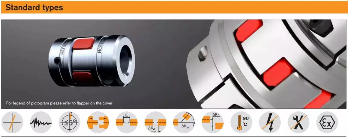
Modifications
The aim of this paper is to investigate the effects of coupling modifications. It shows that such modifications can adversely affect the performance of the coupling mechanism. Moreover, the modifications can be predicted using chemical physics methods. The results presented here are not exhaustive and further research is needed to understand the effects of such coupling modifications.
The modifications to coupling involve nonlinear structural modifications. Four examples of such modifications are presented. Each is illustrated with example applications. Then, the results are verified through experimental and simulated case studies. The proposed methods are applicable to large and complex structures. They are applicable to a variety of engineering systems, including nonlinear systems.
editor by CX 2023-03-27