Hebei JMI basic diaphragm coupling with counterbore
JMI type with counterbore basic typeDiaphragm coupling
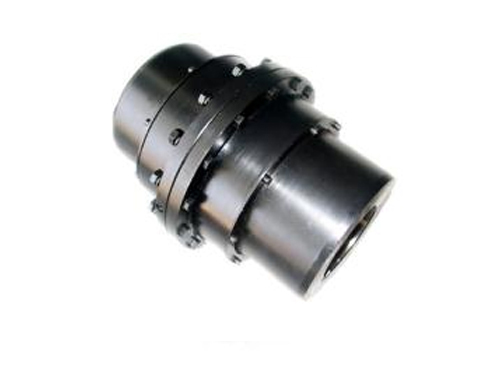
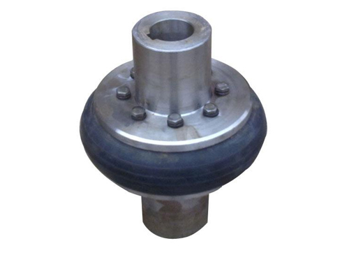
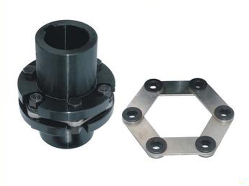
●The diaphragm coupling is composed of several groups of diaphragms (stainless steel thin plate) which are alternately connected with the two halves of the coupling with bolts. Each group of diaphragms is made up of several pieces. The diaphragms are divided into connecting rod type and different The shape of the whole piece.
●It is elastically deformed to compensate for the relative displacement of the connected two shafts. It is a flexible coupling with metal elastic elements. It does not require lubrication, has a compact structure, has a long service life, has no rotation gap, and is not affected by temperature and oil pollution. It has the characteristics of acid resistance, alkali resistance, and is suitable for shaft transmission in high temperature, high speed, and corrosive medium conditions. It is widely used in shaft transmission of various mechanical devices, such as water pumps (especially high-power, chemical pumps), Fans, compressors, hydraulic machinery, petroleum machinery, printing machinery, textile machinery, chemical machinery, mining machinery, metallurgical machinery, aviation (helicopters), high-speed power transmission systems of ships, after being dynamically balanced, have been applied to high-speed transmission shafts. More common.
●Compared with gear coupling, JMI type diaphragm coupling with counterbore has no relative sliding, no lubrication, sealing, noise, basically no maintenance, more convenient manufacturing, and can partially replace gear coupling Device.The diaphragm coupling is inDeveloped industryThe application has been very common. In practical applications, the intermediate shaft type is generally used to improve the performance of the two-axis offset compensation.
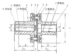
Parameters of JMI basic diaphragm coupling with counterbore
| model | Nominal Torque Tn /N·m | moment High torque Tmax /N·m | license Rotating speed [n] /r·mi -1 | Diameter of shaft hole d (H7) | Length of shaft hole | D | Torsional stiffness C N·m/rad | t | Turning Inertia I kg·m 2 ≈ | 质量 m / kg ≈ | |||
| Y type | J, J1, Type Z | L recommended | |||||||||||
| L | L | L1 | |||||||||||
| JMI1 | 25 | 80 | 6000 | 14 | 32 | - | J1 type is 27 Z1 type is 20 | 35 | 90 | 1 × 10 4 | 8.8 | 0.0007 | 1 |
| 16, 18, 19 | 42 | 30 | |||||||||||
| 20, 22 | 52 | 38 | |||||||||||
| JMI2 | 63 | 180 | 5000 | 18, 19 | 42 | - | 30 | 45 | 100 | 1.4 × 10 4 | 9.5 | 0.001 | 1.3 |
| 20, 22, 24 | 52 | 38 | |||||||||||
| 25 | 62 | 44 | |||||||||||
| JMI3 | 100 | 315 | 5000 | 20, 22, 24 | 52 | - | 38 | 50 | 120 | 1.87 × 10 4 | 11 | 0.0024 | 2.3 |
| 25, 28 | 62 | 44 | |||||||||||
| 30 | 82 | 60 | |||||||||||
| JMI4 | 160 | 500 | 4500 | 24 | 52 | - | 38 | 55 | 130 | 3.12 × 10 4 | 12.5 | 0.0037 | 3.3 |
| 25, 28 | 62 | 44 | |||||||||||
| 30, 32, 35 | 82 | 60 | |||||||||||
| JMI5 | 250 | 710 | 4000 | 28 | 62 | - | 44 | 60 | 150 | 4.32 × 10 4 | 14 | 0.0083 | 5.3 |
| 30-32-35 | 82 | 60 | |||||||||||
| 40 | 112 | 84 | |||||||||||
| JMI6 | 400 | 1120 | 3600 | 32, 35, 38 | 82 | 82 | 60 | 65 | 170 | 6.88 × 10 4 | 15.5 | 0.0159 | 8.7 |
| 40, 42, 45 , 48, 50 | 112 | - | 84 | ||||||||||
| JMI7 | 630 | 1800 | 3000 | 40, 42 | 112 | 112 | 84 | 70 | 210 | 10.35 × 10 4 | 19 | 0.0432 | 14.3 |
| 45, 45, 50 , 55, 56 | - | ||||||||||||
| 60 | 142 | 107 | |||||||||||
| JMI8 | 1000 | 2500 | 2800 | 45, 48 | 112 | 112 | 84 | 80 | 240 | 16.11 × 10 4 | 22.5 | 0.0879 | 22 |
| 50, 55, 56 | - | ||||||||||||
| 60-63-65 | 142 | 107 | |||||||||||
| JMI9 | 1600 | 4000 | 2500 | 55, 56 | 112 | 112 | 84 | 85 | 260 | 26.17 × 10 4 | 24 | 0.1415 | 29 |
| 60, 63, 65 , 70, 71, 75 | 142 | - | 107 | ||||||||||
| 80 | 172 | 132 | |||||||||||
| JMI10 | 2500 | 6300 | 2000 | 63, 65, 70 , 71, 75 | 142 | 142 | 107 | 90 | 280 | 7.88 × 10 4 | 17 | 0.2974 | 52 |
| 80-85-90 | 172 | - | 132 | ||||||||||
| JMI11 | 4000 | 9000 | 1800 | 75 | 142 | 142 | 107 | 95 | 300 | 10.49 × 10 4 | 19.5 | 0.4782 | 69 |
| 80-85-90 | 172 | - | 132 | ||||||||||
| 100, 110 | 212 | 167 | |||||||||||
| JMI12 | 6300 | 12500 | 1600 | 90, 95 | 172 | - | 132 | 120 | 340 | 14.07 × 10 4 | 23 | 0.8067 | 94 |
| 100, 110 , 120, 125 | 212 | 167 | |||||||||||
| JMI13 | 10000 | 18000 | 1400 | 100, 110 , 120, 125 | 212 | - | 167 | 135 | 380 | 19.23 × 10 4 | 28 | 1.7053 | 128 |
| 130, 140 | 252 | 202 | |||||||||||
| JMI14 | 16000 | 28000 | 1200 | 120, 125 | 212 | - | 167 | 150 | 420 | 30.01 × 10 4 | 31 | 2.6832 | 184 |
| 130, 140, 150 | 252 | 202 | |||||||||||
| 160 | 302 | 242 | |||||||||||
| JMI15 | 25000 | 40000 | 1120 | 140, 150 | 252 | - | 202 | 180 | 480 | 47.46 × 10 4 | 37.5 | 4.8015 | 263 |
| 160, 170, 180 | 302 | 242 | |||||||||||
| JMI16 | 40000 | 56000 | 1000 | 160, 170, 180 | 302 | - | 242 | 200 | 560 | 68.09 × 10 4 | 41 | 9.4118 | 384 |
| 190, 200 | 352 | 282 | |||||||||||
| JMI17 | 63000 | 80000 | 900 | 190, 200, 220 | 352 | - | 282 | 220 | 630 | 101.3 × 10 4 | 47 | 18.3753 | 561 |
| 240 | 410 | 330 | |||||||||||
| JMI18 | 100000 | 125000 | 800 | 220 | 352 | - | 282 | 250 | 710 | 161.4 × 10 4 | 54.5 | 28.2033 | 723 |
| 240, 250, 260 | 410 | 330 | |||||||||||
| JMI19 | 160000 | 200000 | 700 | 250, 260 | 410 | - | 330 | 280 | 800 | 79.3 × 10 4 | 48 | 66.5813 | 1267 |
| 280, 300, 320 | 470 | 380 | |||||||||||
Hebei JMI basic diaphragm coupling with counterbore Hebei JMI basic diaphragm coupling with counterbore