
High-torque flange coupling selection sits at the intersection of mechanical engineering, materials science, and practical experience with how heavy equipment actually behaves in service. A coupling rated for the calculated running torque can still fail prematurely if the service factor is wrong, if the hub material cannot handle shock loading, or if the bore-to-shaft connection method introduces a stress concentration that fatigue-cracks the hub within the first year.
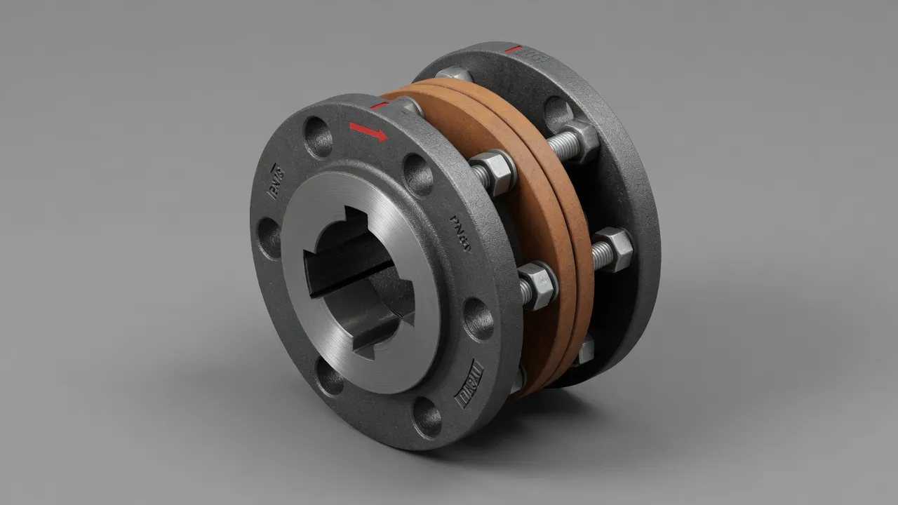
Starting With the Right Torque Calculation
The formula T = 9,550 × kW ÷ RPM gives the nominal running torque. The coupling must be rated for more than this value, because the design torque it must handle includes the peak torques generated by starting, load variations, and shock events.
Example: 315 kW motor driving a jaw crusher at 300 RPM. T_running = 9,550 × 315 ÷ 300 = 10,023 Nm. With a service factor of 3.0: T_design = 30,069 Nm. The coupling must be rated for at least 30,000 Nm — which eliminates all medium-duty coupling products from the selection.
Hub Material Selection for High Torque Applications
| Material | Tensile Strength | Max Bore (Typical) | Shock Resistance | Recommended Use |
|---|---|---|---|---|
| GG25 Grey Cast Iron | 250 MPa | 80 mm | Low — brittle fracture mode | Light industrial only — NOT recommended for high torque |
| SG500 Ductile Iron | 500 MPa | 120 mm | Good — ductile failure mode | Medium-high torque, shock-present applications |
| C45 Carbon Steel | 700 MPa | 200 mm | Excellent — high ductility | Standard for high torque industrial couplings |
| 42CrMo4 Alloy Steel | 1,000+ MPa | 350 mm | Outstanding — impact and fatigue resistant | Extreme torque: mining, steel mill, press drives |
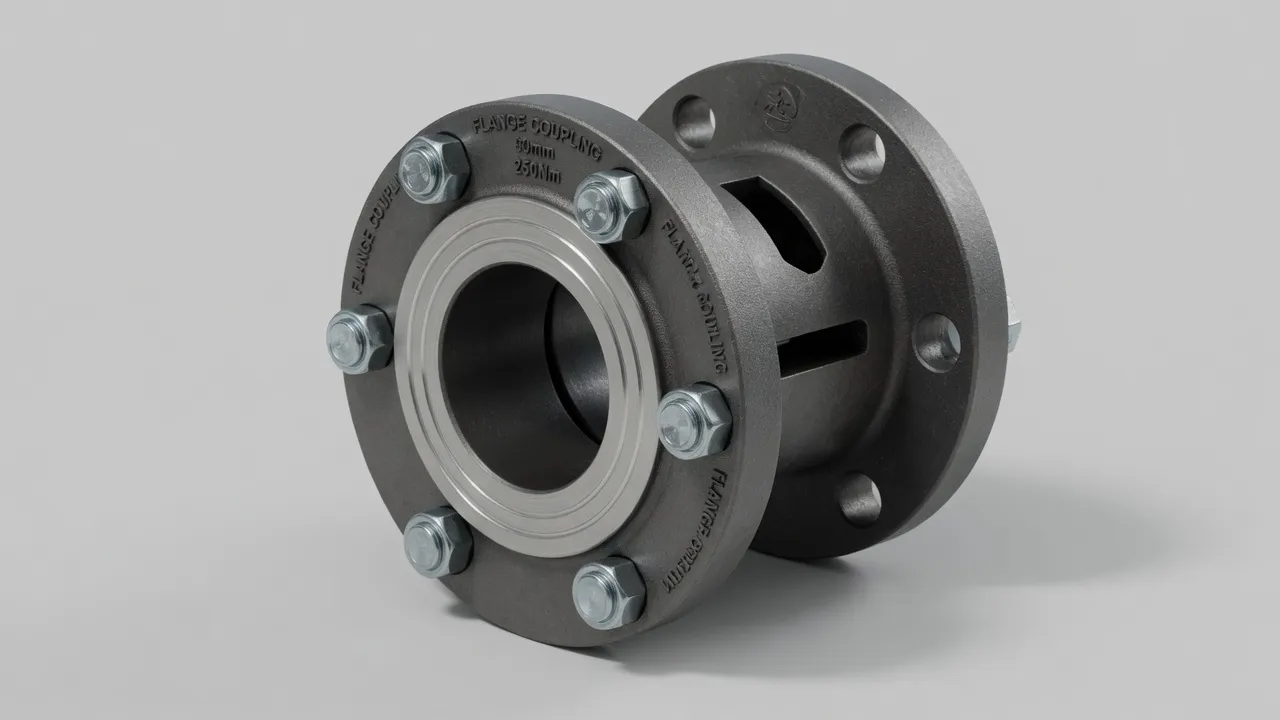
Bore-to-Shaft Connection Method at High Torque
At low torque levels, a simple set screw is adequate. At medium torque, a parallel keyway is standard. At high torque — especially for bore diameters above 80 mm — keyway-based connections require careful analysis of the stress concentration at the keyway root, which can be the limiting factor in fatigue life.
For the highest torque applications (above 20,000 Nm), a shrink disc or hydraulic interference fit is the preferred connection method. These methods create a friction-based torque path across the entire bore contact area, avoiding any stress concentration. The torque capacity of an interference fit scales with bore diameter — at 150 mm bore, a properly designed press fit can transmit over 50,000 Nm without any keyway at all.
Bolt Circle Design and Coupling Bolt Specification
In a bolted rigid flange coupling, the coupling bolts must transmit the full design torque. Grade 10.9 bolts at M20 size provide approximately 3.5× the preload of Grade 8.8 M16 bolts — both commonly specified for high-torque flange couplings. A critically important detail: coupling bolts in high-torque applications should be fitted to close-tolerance bored holes (H7/j6 fit) so that they carry torque in shear as well as through friction. Clearance-fit bolts in oversized holes rely entirely on flange friction and can slip under shock loads.
Frequently Asked Questions
Need Expert Coupling Advice?
Our engineering team in Condell Park NSW is ready to help — free of charge.