
Selecting the wrong flange coupling for a motor-to-pump connection is one of the most common — and most costly — mistakes in industrial power transmission. Get it right, and your drivetrain runs smoothly for decades. Get it wrong, and you face accelerated bearing wear, premature coupling failure, excessive vibration, and unplanned downtime that disrupts entire production lines. This guide walks through every factor that matters when specifying a flange coupling for motor and pump applications, drawing on decades of field experience from Ever Power Flange Couplings Australia Ltd.
Why the Motor-to-Pump Connection Demands Careful Coupling Selection
The junction between a motor shaft and a pump shaft is arguably the most mechanically demanding point in any fluid-handling system. Unlike a simple shaft-to-shaft connection in a controlled environment, a motor-pump drivetrain must simultaneously manage torque transmission, compensate for shaft misalignment, absorb vibration generated by both the motor and the hydraulic forces inside the pump, and endure continuous duty cycles that can span thousands of operating hours. A flange coupling suited to this environment must therefore balance rigidity with enough flexibility to protect both the motor bearings and the pump mechanical seal.
In Australian industrial settings — from water treatment plants across New South Wales to mining process circuits in Western Australia — centrifugal pumps are the most widely deployed rotating machines. The coupling holding the motor and pump together is a small component by cost, but its influence on the reliability of the entire system is enormous. When our engineering team at Ever Power Flange Couplings Australia reviews field failures, coupling-induced problems account for a disproportionate share of bearing replacements and mechanical seal failures, nearly all traceable to poor coupling selection or installation errors that an informed choice could have prevented.
Understanding the Two Primary Flange Coupling Families
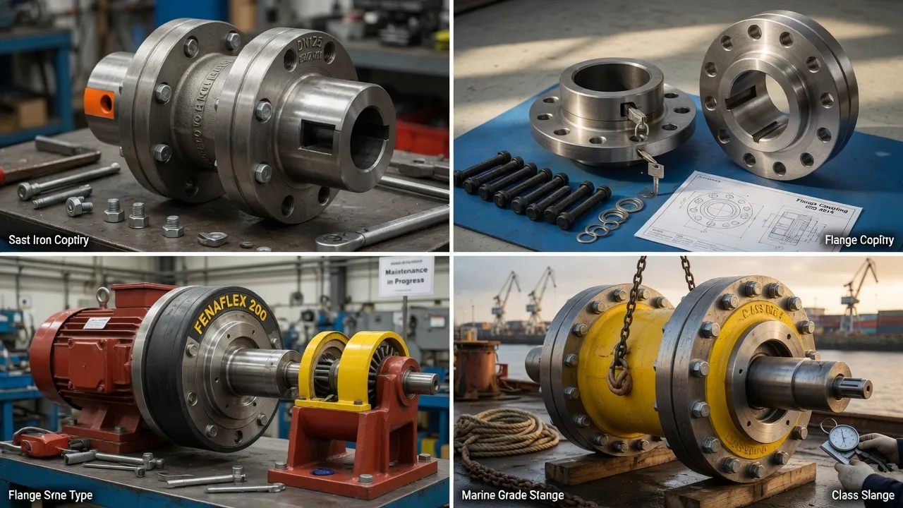
Before diving into selection criteria, it helps to understand the two broad families of flange coupling designs available for pump drive applications: rigid flange couplings and flexible flange couplings. Each has a distinct mechanical character and a corresponding set of applications where it excels.
Rigid Flange Coupling
Delivers a solid, zero-flex connection. Maximum torque transmission efficiency with no energy loss through elastomeric elements. Demands near-perfect shaft alignment — typically within 0.05 mm TIR. Commonly specified for precision pump test rigs, vertically mounted pump-motor sets with close-coupled designs, and applications where torsional stiffness must be maintained for dynamic positioning accuracy.
Flexible Flange Coupling
Incorporates an elastomeric spider or flexible disc element between the two flanged hubs. Accommodates angular misalignment, parallel misalignment, and axial displacement simultaneously. Provides inherent vibration damping and shock absorption, protecting motor bearings and pump mechanical seals. The preferred choice for the vast majority of centrifugal pump and end-suction pump installations.
Step-by-Step Selection Process for Motor-Pump Flange Couplings
The selection process follows a logical sequence. Rushing any step risks an under-specified or over-specified coupling, both of which carry real consequences for reliability and operating cost. Below is the process our engineering team applies to every motor-pump coupling enquiry received at our Condell Park facility.
Determine Peak Torque and Apply a Service Factor
Calculate the nominal torque from motor power and speed (T = 9550 × kW ÷ RPM). Then multiply by an appropriate service factor — typically 1.5 to 2.5 for centrifugal pumps, higher for reciprocating or screw pumps. The coupling’s rated torque capacity must exceed this design torque at all operating conditions, including start-up peaks where inrush torque can reach 2–3× the running value.
Match Bore Diameter to Both Shaft Sizes
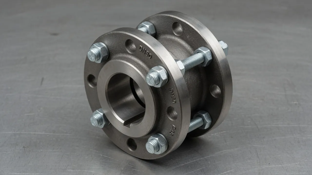
Measure the motor shaft diameter and the pump shaft diameter. These are often different — a 45 mm motor shaft might connect to a 40 mm pump shaft. A flange coupling with a stepped bore or two independently machined hubs accommodates this easily. Confirm whether both shafts use keyways or are plain. Keyway hubs provide a more positive drive and are standard for higher-torque pump applications.
Quantify Expected Shaft Misalignment
Even on a well-aligned pump base, thermal growth during operation introduces dynamic misalignment that can reach 0.1–0.3 mm parallel offset and 0.5° angular deviation. A flexible flange coupling with an elastomeric element handles both comfortably. If your installation involves a baseplate that flexes, a grouted pump base with settlement, or a motor mounted to a different structural frame than the pump, misalignment tolerance becomes a critical design factor — not an afterthought.
Confirm Operating Speed (RPM Rating)
Every coupling carries a maximum RPM rating determined by its dynamic balance grade and material mass distribution. For direct-on-line motors running at 1450 or 2900 RPM, most standard flange couplings are adequate. Variable speed drives pushing a pump to 4000+ RPM require a coupling that has been dynamically balanced to ISO 1940 G6.3 or better. Operating beyond the coupling’s rated speed risks destructive centrifugal forces and rapid fatigue of any elastomeric elements.
Evaluate the Installation Environment
A pump handling hot water, corrosive chemicals, or food-grade liquids imposes environmental demands on the coupling that go beyond mechanical ratings. High-temperature environments above 80°C can degrade standard polyurethane spider elements — a nitrile or EPDM grade may be required. Wet or chemically aggressive surroundings favour cast iron hubs with corrosion-resistant coatings or stainless steel hardware. Food and beverage applications should specify FDA-compliant elastomers and hygienically designed hub profiles that avoid crevice contamination.
Assess Maintenance Access and Preferred Servicing Model
A split flange coupling design, where the hub separates along a central plane, allows the elastomeric spider element to be replaced without dismounting the motor or pump. This dramatically reduces planned maintenance time and is particularly valuable in installations where pump access is limited — a common constraint in basement plant rooms or dense pipework arrangements. If maintenance-free operation is a priority, a metallic disc-element flange coupling requires no periodic spider replacement at all.
Rigid vs Flexible Flange Coupling: Which Is Right for Your Pump?
The most common decision point is whether to specify a rigid flange coupling or a flexible flange coupling. The answer depends on application demands, alignment capability, and the consequences of vibration transmission through the drivetrain.
| Criterion | Rigid Flange Coupling | Flexible Flange Coupling |
|---|---|---|
| Misalignment Tolerance | Minimal (≤0.05 mm TIR) | Up to 1° angular, 0.5 mm parallel |
| Vibration Damping | None — transfers all vibration | Good — elastomeric element absorbs peaks |
| Torque Transmission | 100% mechanical efficiency | Minimal loss through flex element |
| Maintenance | Very low — no wear parts | Spider inspection every 2–3 years |
| Bearing Protection | None — full load transferred to bearings | Good — reduces radial bearing loads |
| Typical Application | Close-coupled pump sets, precision test rigs | General industrial pump drives, HVAC, water treatment |
Material and Construction Options for Pump Drive Flange Couplings
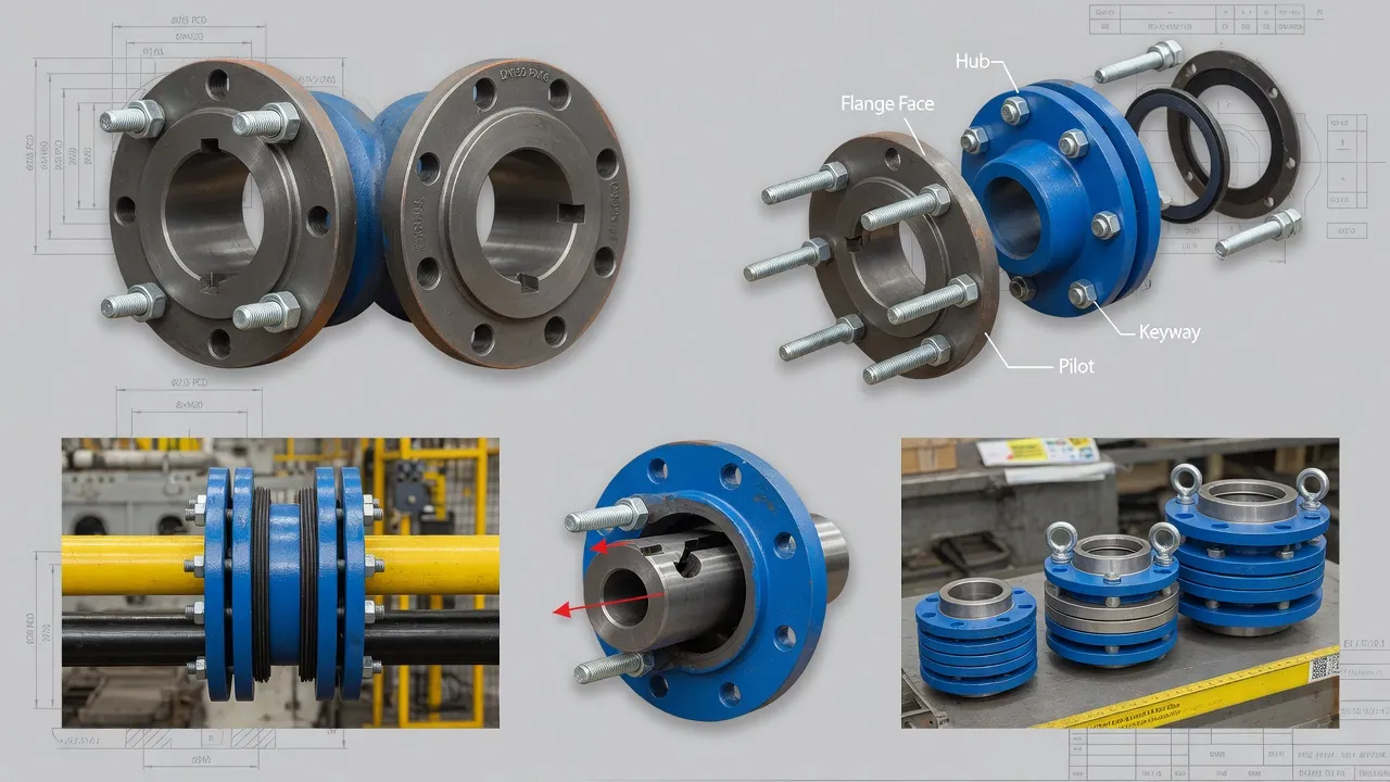
Hub material selection has a larger impact on coupling longevity than many engineers anticipate. The hub must endure both the torque transmitted through the keyway or set screw interface and any bending moment imposed by misalignment forces. Three materials dominate pump drive applications, each with clear trade-offs.
Cast Iron (GG25 / Grade 250)
The workhorse of general industrial pump couplings. Cast iron hubs offer excellent compressive strength, are easily machined to tight bore tolerances, and provide sufficient surface hardness to resist wear at the keyway interface. Standard grey cast iron is appropriate for most water and wastewater pump applications at temperatures up to 120°C. For bore diameters above 80 mm and torques above 2000 Nm, cast iron remains the cost-effective default across the Australian market.
Ductile Iron (SG Iron / Grade 500-7)
Preferred for pump drives subject to shock loads — reciprocating pumps, compressor drives, and applications where fluid hammer is a recurring event. Ductile iron’s superior tensile strength and elongation before fracture make it far more resistant to brittle failure than standard grey iron. Our engineering team recommends ductile iron hubs wherever the pump experiences frequent start-stop cycles or where the driven load includes impact elements.
Steel (C45 / 1045 Carbon Steel)
Steel hubs carry higher torque capacity per unit mass, making them the material of choice for compact, high-torque pump drives where physical size constraints prevent the use of larger cast iron hubs. Steel also machines to closer tolerances, enabling tighter bore-to-shaft fits that reduce any micro-slip at the keyway. Phosphate or zinc coating provides adequate corrosion resistance in most enclosed pump room environments; stainless steel hardware should be specified when the surrounding atmosphere is saline or chemically active.
The Role of the Elastomeric Spider Element in Flexible Flange Couplings
In a flexible flange coupling, the elastomeric spider insert is the component that does the real mechanical work: it transmits torque between the two hubs while simultaneously absorbing misalignment forces and damping vibration. Selecting the correct spider hardness is as important as selecting the coupling size itself, yet it is frequently overlooked during the purchasing process.
Maximum vibration damping and misalignment accommodation. Suited to pump drives with rough running characteristics or flexible baseplates. Lower torque ceiling.
The standard grade for most centrifugal pump drives. Balances damping performance with torque capacity. Handles typical misalignment found on grouted pump bases.
High torsional stiffness for precise speed-ratio applications and variable speed drives. Transmits more shock and vibration — suitable only where alignment is well controlled.
Spider element life in a pump drive application typically runs 25,000 to 50,000 operating hours under correct selection. Premature spider wear — identifiable by rubber dust inside the coupling guard, increased vibration amplitude, or audible slapping sounds during deceleration — is almost always a symptom of under-specification or unaddressed misalignment rather than a product quality issue.
Common Mistakes That Lead to Flange Coupling Failure on Pump Drives
Even a correctly selected coupling will fail early if commissioning or operating practices introduce conditions outside its design envelope. Based on warranty and field investigation cases handled by our team in New South Wales, the following errors account for the majority of premature failures on motor-pump flange coupling installations.
Coupling misalignment doesn’t just shorten elastomeric spider life — it loads the motor bearings and pump mechanical seal with radial forces they were never designed to carry. Laser alignment should be standard practice, not optional, on any motor above 15 kW.
A coupling large enough to fit the shaft may still be under-rated for the peak torque at start-up. Always size by torque first, bore second.
A pump handling fluids at 80°C will grow axially and radially during warm-up. Cold-aligned couplings may exceed their misalignment limit under operating temperature — dynamic alignment checks at operating temperature are essential for high-temperature pump drives.
A rotating coupling without a guard is a safety hazard and also exposes the elastomeric spider to UV radiation and contamination, both of which accelerate material degradation and reduce service life significantly in outdoor Australian environments.
The cost saving of a rigid flange coupling over a flexible equivalent is typically under $150. The cost of a motor bearing replacement or pump seal failure caused by the rigid coupling transmitting misalignment forces can exceed $5,000 in parts and labour alone, before accounting for lost production.
Installation Best Practices for Motor-Pump Flange Couplings
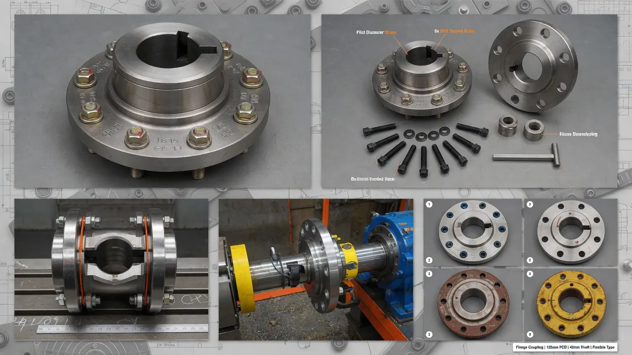
Correct installation is as consequential as correct selection. A well-specified coupling installed poorly will fail just as surely as a poorly specified one. The following practices represent the minimum standard for any motor-pump flange coupling installation:
Hub Fitting
Hubs should be fitted to shafts using a controlled interference or transition fit as specified in the coupling data sheet. Forcing a hub onto a shaft with a hammer risks hub cracking and shaft scoring. Where an interference fit is specified, use a hydraulic press or heat the hub uniformly in an oven to 100–150°C before fitting — never use an open flame that creates localised stress. Confirm that keyways are free from burrs and that key dimensions match the coupling hub slot exactly before assembly.
Shaft Alignment Procedure
Laser shaft alignment is the current industry benchmark. Set the motor on its baseplate with all hold-down bolts finger-tight, complete the laser alignment routine to within half the coupling’s rated misalignment tolerance, then torque the hold-down bolts in a cross-pattern to the specified value. Re-check alignment after final tightening, as bolt torque can shift the motor slightly. Record the final alignment readings and attach them to the equipment file — this baseline is essential for diagnosing future bearing or seal failures.
Spider Element Installation
Insert the elastomeric spider between the hub jaws before bringing the two hubs to their final axial position. Do not stretch or compress the spider during assembly — it should sit freely in the jaw pockets with no residual stress. Check that the axial gap between hub faces matches the coupling manufacturer’s specified DBSE (distance between shaft ends) before closing the coupling guard.
Why Australian Engineers Specify Ever Power Flange Couplings
Ever Power Flange Couplings Australia Ltd. supplies the full spectrum of flange coupling types from our Condell Park, NSW facility — rigid, flexible, split-body, and custom-bored configurations covering bore ranges from 12 mm to 200 mm and torque ratings to 35,000 Nm. Our product range serves water authorities, mining operations, chemical processing plants, food manufacturers, and OEM pump builders across New South Wales and nationally.
Every coupling leaves our facility with dimensional certification, and custom configurations — stepped bores, non-standard DBSE, special spider materials, stainless hardware — are handled as standard engineering requests, not exceptions. If you have a motor-pump coupling requirement that doesn’t fit a catalogue size, our team can typically provide a drawing approval within 48 hours of receiving your shaft and torque data.
Need a Flange Coupling Recommendation for Your Pump Drive?
Send us your motor and pump shaft data and we’ll specify the right coupling — at no charge.
Frequently Asked Questions
27 Harley Crescent, Condell Park NSW 2201, New South Wales, Australia
+61 29708 3322 |
[email protected] |
Contact Us