
A flange coupling is one of the most fundamental mechanical components in rotating machinery — yet its design principles are surprisingly misunderstood outside specialist engineering circles. Walk through any industrial facility in New South Wales and you will find flange couplings on pump drives, fan systems, conveyors, and compressors. What all these applications share is a need to transmit rotational torque from one shaft to another, reliably, over long service periods, with minimum maintenance.
The Basic Principle: What a Flange Coupling Actually Does
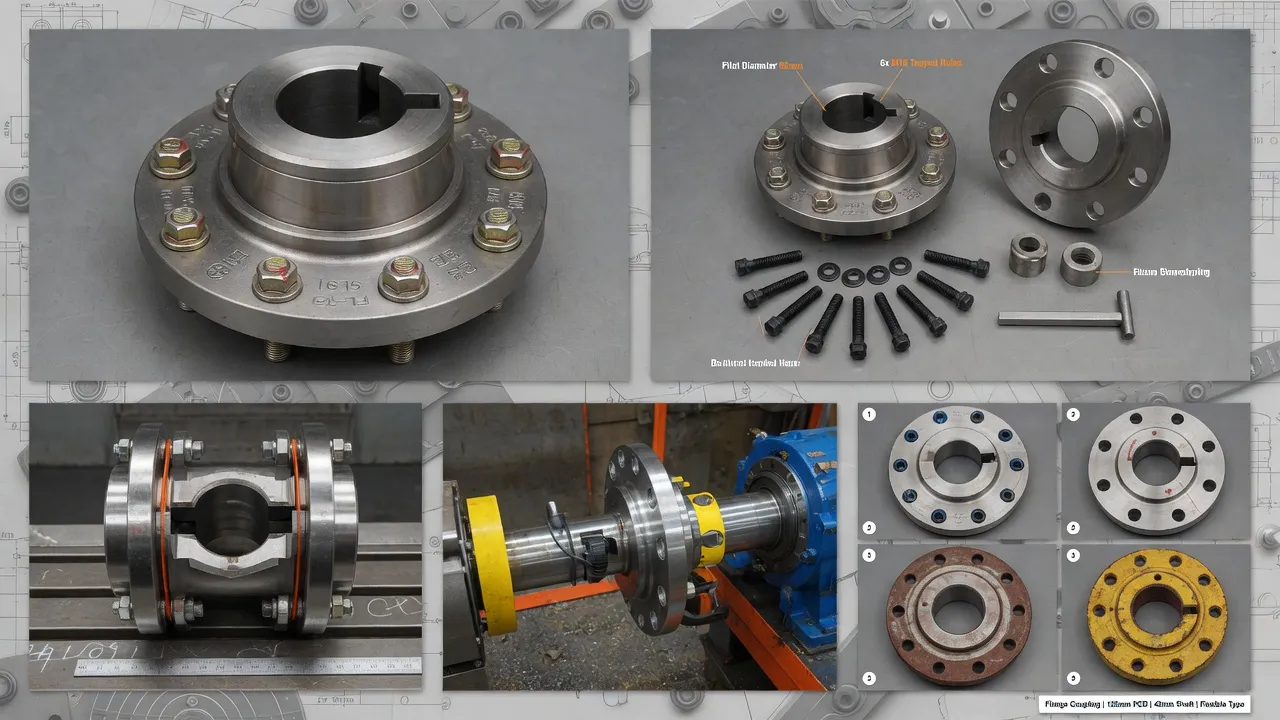
At its core, a flange coupling connects two shaft ends and transmits the torque applied to one shaft across to the other. The coupling consists of two machined hubs — one fitted to each shaft — each carrying a flat, circular flange face with a precision bolt circle. The two flanges are bolted together face-to-face, creating a mechanically rigid or semi-flexible joint depending on whether an intermediate elastomeric element is included between the flange faces.
The torque transmission path in a rigid flange coupling is entirely through the bolt preload — the bolts are tightened to a specified torque that creates sufficient clamping force to prevent any rotational slip between the flange faces under the maximum design load. In a flexible variant, torque passes through the elastomeric tyre element, and the elastic deformation of this element is what provides misalignment accommodation and vibration damping.
Rigid vs Flexible: The Design Split That Defines Application Suitability
The most important distinction in the flange coupling product family is between rigid and flexible designs. The choice between them determines how the entire drivetrain behaves — what forces reach the bearings, how vibration propagates, and how tolerant the system is of the small shaft misalignments that develop inevitably during service.
Rigid Flange Coupling
Zero flex between hubs. Maximum torque efficiency with no energy absorption in the coupling element. Demands shaft-to-shaft alignment within 0.05 mm TIR. Any misalignment transfers as cyclic bending load to motor and pump bearings. Used on precision test rigs, encoder drives, and close-coupled pump sets where alignment is guaranteed.
Flexible Flange Coupling
Elastomeric tyre element between hubs absorbs angular, parallel, and axial misalignment. Provides vibration damping and shock absorption. Protects bearings and mechanical seals from misalignment forces. The standard choice for centrifugal pumps, fans, compressors, and general industrial drives across Australia.
How Torque Is Transmitted Through a Flange Coupling
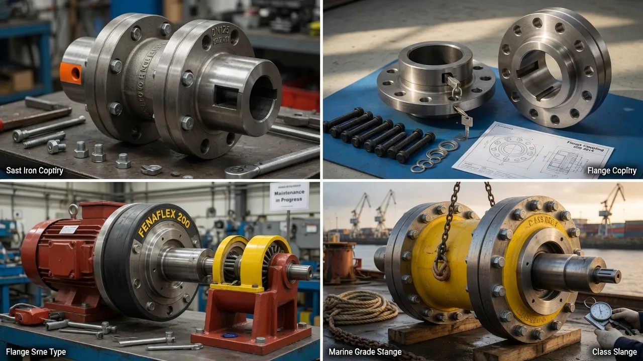
In a bolted rigid flange coupling, torque transmission relies on friction between the mating flange faces generated by bolt preload, supplemented by keyway-to-shaft engagement in each hub. The keyway carries the primary torque — the key shears in a plane parallel to the shaft axis, transferring torque from the shaft to the hub. The coupling bolts then carry the torque from one hub flange to the other through the bolt circle.
In a flexible flange coupling, the elastomeric element takes the torque transmission role. The tyre material deforms in shear as torque is applied, and the elastic restoring force transmits the load. Spider hardness selection — typically 80A, 92A, or 98A Shore — is a direct trade-off between misalignment accommodation, vibration damping, and torque capacity.
Flange Coupling Key Dimensions Explained
| Dimension | Definition | Why It Matters |
|---|---|---|
| Bore Diameter | Internal diameter machined to fit the shaft | Must match shaft size — H7 tolerance standard for precision fit |
| Bolt Circle Diameter (PCD) | Diameter of the circle on which the bolt holes sit | Determines torque arm — larger PCD = higher torque capacity per bolt |
| Flange OD | Overall outer diameter of the flange face | Sets the physical envelope — must clear guards and pipework |
| DBSE | Distance Between Shaft Ends | Critical for spacer types and pump maintenance access |
| Hub Length | Axial length of the hub body over the shaft | Determines keyway engagement length and overhung load capacity |
Hub-to-Shaft Connection Methods
Keyway (Parallel Key): The most common method for general industrial couplings. A rectangular key machined to ISO 773 dimensions sits in matching keyways in both shaft and hub bore, transmitting torque through compressive bearing on the keyway faces. Reliable and easy to install and remove.
Set Screw: A threaded screw bearing directly on the shaft OD. Low-cost and simple for light-duty connections. Not suitable for shock loads or frequent reversal.
Interference Fit: The hub bore is machined 0.01–0.05 mm smaller than the shaft OD. Creates a friction-based torque transmission that is highly concentric with no backlash and no stress concentration from keyways. Preferred for high-speed and precision couplings.
Where Flange Couplings Are Used Across Australian Industry
| Industry Sector | Typical Application | Coupling Type Preferred |
|---|---|---|
| Water & Wastewater | Centrifugal pump drives at treatment plants | Flexible flange (F-type tyre) |
| Mining | Conveyor drives, crusher shaft connections | Heavy-duty rigid or flexible flange |
| Marine | Engine to gearbox or pump connections | Marine flexible flange with classification cert |
| Food & Beverage | Mixer, filler, and conveyor shaft connections | Flexible flange with hygienic hub profile |
| Power Generation | Generator shaft coupling | Rigid or disc coupling at high torque |
Frequently Asked Questions
Need Expert Coupling Advice?
Our engineering team in Condell Park NSW is ready to help — free of charge.