Product Description
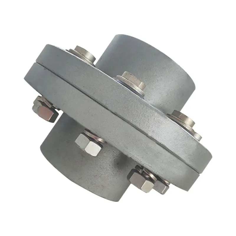
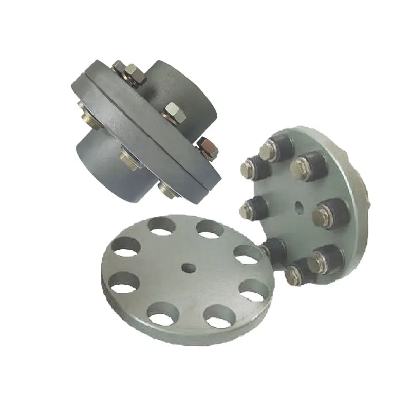
Ductile iron universal joint
1) The Universal Flanged Adaptors and Couplings are designed for pipelines, As a wide tolerance system
2) It will fit most standard pipe materials and therefore dramatically reduces the number of dedicated Flanged Adaptors and couplings which need to be stocked for maintenance purposes.
3) It is suitable for steel, GRP, PVC, PE, Ductile Iron, Cast Ironand Asbestors Cement. When connecting PE pipes, It is important that pipe inserts are fitted to the PE pipes.
1) All the flanged adaptors are assembled by ” T ” bolts.
2) Bolts, Nuts and Washers are in carbon steel Grade 4.8, 8.8 with zinc plated, dacromet coating or according to customer’s request.
3) Body material is Ductile iron GGG500-7.
4) CHINAMFG bonded epoxy powder coating in blue, black or red or according to customer’srequest.
5) Gaskets material: E. P. D. M., NBR or SBR.
6) Accommodate BS, DIN, ANSI flange drillings. Specification Unit Weight Sealing Ranges(mm) inches mm kgs 2″ 50 3.6 59~732 1/2″ 65 4.50 72~853″ 80 4.83 88~1034″ 100 5.51 108~1285″ 125 7.74 132~1546″ 150 8.32 159~1827″ 175 11.30 192~2098″ 200 9.95 218~23510″ 250 14.50 271~28912″ 300 18.62 322~34014″ 350 26.00 374~39116″ 400 28.85 417~43718″ 450 33.40 480~5571″ 500 50.00 526~54624″ 600 54.10 630~650.
FAQ
1. Can I get free samples?
A: Yes, we can provide you the free samples, but you need to bear their own delivery costs.
2. Can I request to change the form of packaging and transportation?
A: Yes, We can change the form of the packaging and transportation according to your request, but you have to bear their own costs incurred during this period and the spreads.
3. Can I request to advance the shipment?
A: It should be depends on whether there is sufficient inventory in our warehouse.
4. Can I have my own Logo on the product?
A: Yes, you can send us your drawing and we can make your logo, but you have to bear their own the cost.
5. Can you produce the products according to my own drawings?
A: Yes, we can produce the products according to your drawings that will be most satisfy you.
6. Which price terms could accepted?
A: FOB,CIF all acceptable.

Proper Installation and Alignment of Flange Couplings
Installing and aligning a flange coupling properly is crucial to ensure its optimal performance and to prevent premature wear or failure. Here are the steps to follow for a successful installation:
- Prepare the Components: Before starting the installation, ensure that all the components, including the flange coupling, shafts, and fasteners, are clean and free from dirt or debris. Inspect the coupling for any visible damage or defects.
- Check Shaft Alignment: Verify the alignment of the shafts before installing the flange coupling. Misalignment can lead to increased stresses on the coupling and other connected equipment.
- Use Proper Lubrication: Apply the recommended lubricant to the contact surfaces of the flange coupling. Proper lubrication reduces friction and wear, enhancing the coupling’s lifespan.
- Align the Flange Coupling: Position the flange coupling between the shafts and ensure that the bolt holes are aligned with the corresponding holes in the shafts.
- Insert Fasteners: Insert the bolts or screws through the bolt holes and hand-tighten them. Avoid fully tightening any fasteners at this stage.
- Check Runout: Measure the runout of the coupling during rotation to verify that it is within acceptable limits. Excessive runout indicates a misaligned coupling.
- Properly Torque Fasteners: Using a torque wrench, tighten the fasteners in a cross-pattern to the manufacturer’s recommended torque values. This ensures even distribution of the load and prevents distortion of the flange coupling.
- Recheck Alignment: After torquing the fasteners, recheck the shaft alignment to ensure it has not shifted during the tightening process.
- Inspect the Assembly: Conduct a final visual inspection of the installed flange coupling and surrounding components to verify that everything is properly aligned and secured.
- Perform Test Run: Run the equipment with the newly installed flange coupling under no-load conditions initially to check for any unusual vibrations or noises.
- Monitor Performance: During the initial operation and throughout regular use, monitor the flange coupling’s performance and check for signs of wear, misalignment, or other issues.
Professional Installation: If you are unsure about the installation process or need to install a flange coupling in a complex system, consider seeking assistance from a qualified professional or coupling manufacturer’s technical support team. Proper installation is essential for ensuring the long-term reliability and performance of the flange coupling and the connected equipment.
Electrical Insulation in Flange Couplings
In certain applications, flange couplings may need to provide electrical insulation between shafts to prevent the flow of electrical currents and ensure safety and proper functioning. The handling of electrical insulation in flange couplings depends on the design and materials used:
1. Material Selection: Some flange couplings are manufactured using electrically insulating materials, such as certain polymers or composite materials. These materials have high resistivity and do not conduct electricity, effectively isolating one shaft from the other.
2. Sleeve or Coating: In some cases, a non-conductive sleeve or coating is added to the coupling to provide electrical insulation. This sleeve can be made from materials like rubber or other insulating compounds.
3. Insulating Inserts: Flange couplings may incorporate insulating inserts or liners between the mating surfaces to prevent electrical conduction.
4. Dielectric Grease: Dielectric grease, a non-conductive and water-resistant grease, can be used to fill any gaps between mating surfaces and enhance the electrical insulation properties of the flange coupling.
It’s crucial to ensure that the chosen flange coupling provides adequate electrical insulation for the specific application. The level of insulation required will depend on the electrical characteristics and voltages involved in the system. Additionally, proper installation and maintenance are essential to maintain the integrity of the electrical insulation over time.
How Does a Flange Coupling Protect Connected Equipment from Shock Loads and Vibrations?
A flange coupling plays a crucial role in protecting connected equipment from shock loads and vibrations by absorbing and dampening the impact and oscillations. The design and material properties of flange couplings contribute to their ability to mitigate shock and vibrations effectively. Below are the key factors explaining how flange couplings provide protection:
1. Flexibility: Flexible flange couplings are designed with elastomeric or metallic elements that offer flexibility between the connected shafts. When subjected to shock loads or vibrations, these elements can absorb and dissipate the energy, preventing it from transmitting to the connected equipment. The flexibility allows the coupling to accommodate misalignment and minor shocks, reducing the stress on the system.
2. Damping Properties: Elastomeric elements used in certain flange coupling designs possess inherent damping properties. These materials can absorb and dissipate vibrational energy, reducing resonance and preventing harmful vibrations from being amplified in the system.
3. Misalignment Compensation: Flange couplings with flexible elements can compensate for certain degrees of misalignment between the shafts. Misalignment can lead to additional forces and vibrations in the system, but the coupling’s ability to accommodate this misalignment reduces the impact on the connected equipment.
4. Resilience: Flange couplings made from materials like steel or other alloys have high resilience and can withstand sudden shock loads without permanent deformation. This resilience helps maintain the coupling’s integrity and allows it to continue functioning effectively after exposure to shock events.
5. Friction Damping: Some rigid flange coupling designs incorporate friction damping features. These couplings rely on friction between the mating surfaces to dampen vibrations and prevent resonant frequencies from causing issues in the system.
6. Material Selection: The choice of materials for both flexible and rigid flange couplings is critical in their ability to protect connected equipment from shock loads and vibrations. High-quality materials with appropriate mechanical properties, such as strength and elasticity, enhance the coupling’s ability to withstand shocks and vibrations.
7. Proper Installation: Correct installation and alignment of the flange coupling are essential to ensure it functions as intended. Properly installed couplings can effectively manage shocks and vibrations, while misaligned couplings may experience premature wear and transmit higher forces to the connected equipment.
8. Maintenance: Regular maintenance, including inspection, lubrication, and monitoring, ensures that the flange coupling continues to provide protection against shocks and vibrations throughout its service life.
In summary, flange couplings protect connected equipment from shock loads and vibrations by providing flexibility, damping properties, misalignment compensation, resilience, and friction damping. The selection of suitable materials, proper installation, and regular maintenance further enhance their performance in protecting industrial machinery and equipment from potential damage caused by dynamic forces.


editor by CX 2023-11-16
China supplier Fql290 Stainless Steel Woodon China Flange Joint Magnetic Universal Coupling flange coupling
Product Description
| Product Name | Cardan Shaft |
| Product Model | SWC-I75A-335+40 |
| Main Material | 35CrMo or 45# Steel |
| Nominal Torque | 500 N.M |
| Normal Length | 335 mm |
| Length Compensation | 40 mm |

How Does a Flange Coupling Handle Angular, Parallel, and Axial Misalignment?
A flange coupling is designed to accommodate various types of misalignment that may occur between two shafts. Here’s how it handles different types of misalignment:
- Angular Misalignment: Flange couplings can handle angular misalignment by allowing a slight flexing or bending of the flexible elements. The coupling’s flexible components, such as elastomeric or metallic elements, can bend and compensate for angular misalignment between the shafts. This flexibility ensures that the coupling can transmit torque smoothly even when the shafts are not perfectly aligned in a straight line.
- Parallel Misalignment: Flange couplings can also accommodate parallel misalignment between the shafts. When the two shafts are slightly offset in a parallel direction, the flexible elements in the coupling can move laterally to accommodate this misalignment. This lateral movement helps prevent excessive forces and wear on the coupling and connected equipment, ensuring efficient power transmission even in slightly misaligned conditions.
- Axial Misalignment: Axial misalignment refers to the situation when two shafts are displaced along their common axis. Flange couplings are not specifically designed to handle large axial misalignment. However, certain types of flange couplings may have limited axial movement capabilities due to the flexibility of their components. In some cases, an additional feature like an end float or sliding flange design may be incorporated to accommodate limited axial movement.
It is important to note that while flange couplings can handle a certain degree of misalignment, excessive misalignment can lead to premature wear and failure of the coupling. Regular maintenance and proper alignment of the shafts are essential to ensure the coupling’s optimal performance and longevity.
Common Installation Mistakes to Avoid When Using Flange Couplings
Proper installation is crucial for the efficient and reliable operation of flange couplings. Avoiding common installation mistakes can help ensure the longevity and optimal performance of the coupling. Here are some common installation mistakes to avoid:
1. Improper Alignment: One of the most critical aspects of flange coupling installation is ensuring proper shaft alignment. Misalignment can lead to increased wear, vibrations, and decreased power transmission efficiency. Always use precision alignment tools and techniques to achieve accurate alignment.
2. Over-Tightening: Over-tightening the coupling’s bolts can cause excessive stresses on the coupling and connected equipment. It may lead to premature failure or deformation of the coupling. Follow the manufacturer’s recommended torque values for tightening the bolts.
3. Under-Tightening: On the other hand, under-tightening the bolts may result in a loose connection, leading to misalignment and potential damage to the coupling during operation. Make sure to achieve the proper torque during installation.
4. Lack of Lubrication: Insufficient or improper lubrication of the coupling’s components can result in increased friction and wear. Follow the manufacturer’s guidelines for lubrication, and use the recommended lubricant to ensure smooth operation.
5. Contamination: Avoid introducing dirt, debris, or foreign particles into the coupling during installation. Contaminants can lead to wear and damage over time, reducing the coupling’s performance.
6. Incorrect Coupling Selection: Choosing the wrong type or size of flange coupling for the application can lead to performance issues. Consider factors like torque, speed, load, and operating environment when selecting the coupling.
7. Lack of Inspection: After installation, regularly inspect the flange coupling and its components for signs of wear, damage, or misalignment. Early detection of issues allows for timely maintenance and prevents potential system failures.
8. Ignoring Manufacturer Guidelines: Always follow the manufacturer’s installation instructions and guidelines. Each flange coupling may have specific requirements and recommendations that must be adhered to for proper functioning.
9. Incorrect Shaft Fit: Ensure that the coupling properly fits the shafts’ dimensions. A loose fit can cause slippage, while a tight fit can lead to stress concentration and premature failure.
10. Inadequate Inspection of Components: Before installation, inspect all coupling components, including flanges, bolts, and keyways, for any defects or damage. Replace any damaged parts before installation.
By avoiding these common installation mistakes, you can maximize the performance and lifespan of flange couplings in your mechanical systems.

Can Flange Couplings Accommodate High Torque and High-Speed Applications?
Yes, flange couplings are designed to accommodate both high torque and high-speed applications. They are capable of transmitting significant amounts of torque between shafts while maintaining stable and efficient power transmission. The ability to handle high torque and high-speed applications depends on various factors, including the design, material, and size of the flange coupling.
1. Design: Flange couplings are available in different designs, such as rigid flange couplings and flexible flange couplings. Rigid flange couplings are more suitable for applications that require precise shaft alignment and minimal misalignment. On the other hand, flexible flange couplings can accommodate slight misalignments and are suitable for applications where shock or vibration may occur. The design of the coupling is crucial in determining its torque and speed capabilities.
2. Material: Flange couplings are manufactured from various materials, including steel, stainless steel, aluminum, and other alloys. The material selection is essential in determining the coupling’s strength, durability, and resistance to wear and fatigue. High-quality materials are used in flange couplings for high torque and high-speed applications to ensure their reliability and performance.
3. Size and Dimensions: The size and dimensions of the flange coupling play a significant role in determining its torque and speed ratings. Larger flange couplings with increased diameter and thickness can handle higher torque and speed compared to smaller couplings. It is essential to choose the appropriate size of the coupling based on the application’s torque and speed requirements.
4. Surface Finish: The surface finish of the flange coupling is critical, especially in high-speed applications. A smooth surface finish reduces friction and wear between the mating surfaces of the flanges, bolts, and nuts, thereby improving the overall efficiency of the coupling.
5. Lubrication: Proper lubrication is essential for flange couplings in high-speed and high-torque applications. Lubricants help reduce friction and wear, dissipate heat, and prevent premature failure of the coupling components.
6. Manufacturer’s Recommendations: It is crucial to follow the manufacturer’s recommendations and guidelines regarding the maximum torque and speed ratings of the flange coupling. Exceeding the recommended limits can lead to coupling failure and potential damage to the connected equipment.
In conclusion, flange couplings can be effectively used in high torque and high-speed applications when selected and maintained properly. Choosing the right design, material, size, and adhering to the manufacturer’s guidelines ensures that the flange coupling can handle the required torque and rotational speed efficiently and reliably.
editor by CX 2023-09-07
China manufacturer Stainless Steel Coupling Gear Rigid Roller Chain Fluid Tyre Grid Jaw Spider HRC Nm Motor Flange Gear Pump Rubber Spline Shaft Flexible Universal Joint Coupling flange coupling
Product Description
Stainless Steel Coupling Gear Rigid Roller Chain Fluid Tyre Grid Jaw Spider HRC Nm Motor Flange Gear Pump Rubber Spline Shaft Flexible Universal Joint Coupling
Product Description
Main products
Coupling refers to a device that connects 2 shafts or shafts and rotating parts, rotates together during the transmission of motion and power, and does not disengage under normal conditions. Sometimes it is also used as a safety device to prevent the connected parts from bearing excessive load, which plays the role of overload protection.
Couplings can be divided into rigid couplings and flexible couplings.
Rigid couplings do not have buffering property and the ability to compensate the relative displacement of 2 axes. It is required that the 2 axes be strictly aligned. However, such couplings are simple in structure, low in manufacturing cost, convenient in assembly and disassembly, and maintenance, which can ensure that the 2 axes are relatively neutral, have large transmission torque, and are widely used. Commonly used are flange coupling, sleeve coupling and jacket coupling.
Flexible coupling can also be divided into flexible coupling without elastic element and flexible coupling with elastic element. The former type only has the ability to compensate the relative displacement of 2 axes, but cannot cushion and reduce vibration. Common types include slider coupling, gear coupling, universal coupling and chain coupling; The latter type contains elastic elements. In addition to the ability to compensate the relative displacement of 2 axes, it also has the functions of buffering and vibration reduction. However, due to the strength of elastic elements, the transmitted torque is generally inferior to that of flexible couplings without elastic elements. Common types include elastic sleeve pin couplings, elastic pin couplings, quincunx couplings, tire type couplings, serpentine spring couplings, spring couplings, etc
Coupling performance
1) Mobility. The movability of the coupling refers to the ability to compensate the relative displacement of 2 rotating components. Factors such as manufacturing and installation errors between connected components, temperature changes during operation and deformation under load all put CZPT requirements for mobility. The movable performance compensates or alleviates the additional load between shafts, bearings, couplings and other components caused by the relative displacement between rotating components.
(2) Buffering. For the occasions where the load is often started or the working load changes, the coupling shall be equipped with elastic elements that play the role of cushioning and vibration reduction to protect the prime mover and the working machine from little or no damage.
(3) Safe, reliable, with sufficient strength and service life.
(4) Simple structure, easy to assemble, disassemble and maintain.
How to select the appropriate coupling type
The following items should be considered when selecting the coupling type.
1. The size and nature of the required transmission torque, the requirements for buffering and damping functions, and whether resonance may occur.
2. The relative displacement of the axes of the 2 shafts is caused by manufacturing and assembly errors, shaft load and thermal expansion deformation, and relative movement between components.
3. Permissible overall dimensions and installation methods, and necessary operating space for assembly, adjustment and maintenance. For large couplings, they should be able to be disassembled without axial movement of the shaft.
In addition, the working environment, service life, lubrication, sealing, economy and other conditions should also be considered, and a suitable coupling type should be selected by referring to the characteristics of various couplings.
If you cannot determine the type, you can contact our professional engineer
Related products
Company Profile
Our Equipments
Main production equipment:
Large lathe, surface grinder, milling machine, gear shaper, spline milling machine, horizontal broaching machine, gear hobbing machine, shaper, slotting machine, bench drilling machine, radial drilling machine, boring machine, band sawing machine, horizontal lathe, end milling machine, crankshaft grinder, CNC milling machine, casting equipment, etc.
Inspection equipment:
Dynamic balance tester, high-speed intelligent carbon and sulfur analyzer, Blochon optical hardness tester, Leeb hardness tester, magnetic yoke flaw detector, special detection, modular fixture (self-made), etc.
Machining equipments
Heat equipment
Our Factory
Application – Photos from our partner customers
Company Profile
Our leading products are mechanical transmission basic parts – couplings, mainly including universal couplings, drum gear couplings, elastic couplings and other 3 categories of more than 30 series of varieties. It is widely used in metallurgical steel rolling, wind power, hydropower, mining, engineering machinery, petrochemical, lifting, paper making, rubber, rail transit, shipbuilding and marine engineering and other industries.
Our factory takes the basic parts of national standards as the benchmark, has more than 40 years of coupling production experience, takes “scientific management, pioneering and innovation, ensuring quality and customer satisfaction” as the quality policy, and aims to continuously provide users with satisfactory products and services. The production is guided by reasonable process, and the ISO9001:2015 quality management system standard is strictly implemented. We adhere to the principle of continuous improvement and innovation of coupling products. In recent years, it has successfully developed 10 national patent products such as SWF cross shaft universal coupling, among which the double cross shaft universal joint has won the national invention patent, SWF cross shaft universal coupling has won the new product award of China’s general mechanical parts coupling industry and the ZHangZhoug Province new product science and technology project.
Our factory has strong technical force, excellent process equipment, complete professional production equipment, perfect detection means, excellent after-sales service, various products and complete specifications. At the same time, we can provide the design and manufacturing of special non-standard products according to the needs of users. Our products sell well at home and abroad, and are trusted by the majority of users. We sincerely welcome friends from all walks of life at home and abroad to visit and negotiate for common development.p

Impact of Flange Coupling on Noise and Vibration in a Mechanical System
Flange couplings play a significant role in the overall noise and vibration levels of a mechanical system. The type of flange coupling used and its design characteristics can have varying effects on the system’s noise and vibration. Let’s explore how flange couplings impact noise and vibration in a mechanical system:
1. Rigid Flange Couplings:
Rigid flange couplings, being solid and inflexible connections, are generally considered to be more rigid than flexible couplings. As a result, they can transmit vibrations more directly between the connected shafts and the rest of the system. The lack of misalignment compensation can lead to higher stress on the bearings and other components, contributing to increased vibration levels.
However, rigid flange couplings are also less likely to introduce any additional sources of vibration due to their simple and solid construction. If the system is well-aligned and requires no misalignment compensation, rigid flange couplings can provide a stable and reliable connection.
2. Flexible Flange Couplings:
Flexible flange couplings are designed to dampen vibrations and shocks in the system. The flexibility of these couplings allows them to absorb and minimize the transmission of vibrations between the connected shafts and the rest of the system. As a result, flexible flange couplings can reduce overall vibration levels and provide a smoother and quieter operation.
Additionally, the misalignment compensation capability of flexible flange couplings helps to reduce stress on the bearings and other components. By accommodating misalignment, these couplings prevent the system from experiencing excessive vibrations that can lead to premature wear and failures.
Overall Impact:
The choice of flange coupling design will significantly influence the noise and vibration levels in the mechanical system. In applications where precise alignment is crucial, rigid flange couplings may be preferred despite potentially higher vibration levels. On the other hand, flexible flange couplings are ideal for systems where misalignment is expected or where vibration dampening is a priority.
It’s important to consider the specific requirements of the application when selecting a flange coupling. Factors such as torque capacity, operating conditions, alignment needs, and desired noise and vibration levels should all be taken into account. Proper installation and maintenance of the chosen flange coupling can also impact its performance in reducing noise and vibration levels in the mechanical system.
Flange Couplings in Precision Motion Control Systems
Yes, flange couplings can be used in precision motion control systems, provided they are designed and selected appropriately for the specific application. Precision motion control systems often require high accuracy, repeatability, and minimal backlash. Flange couplings can meet these requirements when certain factors are considered:
1. Backlash: Precision motion control systems require minimal or zero backlash to ensure accurate positioning. Flexible flange couplings with no metal-to-metal contact, such as elastomeric or beam couplings, are preferred for these applications.
2. Rigidity: Flange couplings should have sufficient torsional rigidity to maintain the accuracy of the motion system. Rigid flange couplings made from materials like aluminum or steel can provide higher torsional stiffness.
3. Misalignment Compensation: In precision systems, alignment errors must be minimized. Flexible flange couplings can compensate for minor misalignments between shafts while maintaining precise motion transmission.
4. Low Inertia: Flange couplings with low inertia are desirable as they reduce the overall inertia of the system, enabling faster acceleration and deceleration during motion.
5. Material Selection: The choice of material is critical in precision motion control applications. Materials with high strength-to-weight ratios and minimal deformation under load are preferred.
6. Environmental Factors: Consider the environmental conditions in which the flange coupling will operate. For instance, in vacuum environments or cleanrooms, non-lubricated or special coatings may be necessary.
When selecting a flange coupling for precision motion control systems, it’s essential to consider the specific requirements of the application, including speed, torque, misalignment, and environmental factors. Regular maintenance and periodic checks for wear and misalignment are crucial to ensure the continued performance and accuracy of the motion control system.
Can Flange Couplings Accommodate High Torque and High-Speed Applications?
Yes, flange couplings are designed to accommodate both high torque and high-speed applications. They are capable of transmitting significant amounts of torque between shafts while maintaining stable and efficient power transmission. The ability to handle high torque and high-speed applications depends on various factors, including the design, material, and size of the flange coupling.
1. Design: Flange couplings are available in different designs, such as rigid flange couplings and flexible flange couplings. Rigid flange couplings are more suitable for applications that require precise shaft alignment and minimal misalignment. On the other hand, flexible flange couplings can accommodate slight misalignments and are suitable for applications where shock or vibration may occur. The design of the coupling is crucial in determining its torque and speed capabilities.
2. Material: Flange couplings are manufactured from various materials, including steel, stainless steel, aluminum, and other alloys. The material selection is essential in determining the coupling’s strength, durability, and resistance to wear and fatigue. High-quality materials are used in flange couplings for high torque and high-speed applications to ensure their reliability and performance.
3. Size and Dimensions: The size and dimensions of the flange coupling play a significant role in determining its torque and speed ratings. Larger flange couplings with increased diameter and thickness can handle higher torque and speed compared to smaller couplings. It is essential to choose the appropriate size of the coupling based on the application’s torque and speed requirements.
4. Surface Finish: The surface finish of the flange coupling is critical, especially in high-speed applications. A smooth surface finish reduces friction and wear between the mating surfaces of the flanges, bolts, and nuts, thereby improving the overall efficiency of the coupling.
5. Lubrication: Proper lubrication is essential for flange couplings in high-speed and high-torque applications. Lubricants help reduce friction and wear, dissipate heat, and prevent premature failure of the coupling components.
6. Manufacturer’s Recommendations: It is crucial to follow the manufacturer’s recommendations and guidelines regarding the maximum torque and speed ratings of the flange coupling. Exceeding the recommended limits can lead to coupling failure and potential damage to the connected equipment.
In conclusion, flange couplings can be effectively used in high torque and high-speed applications when selected and maintained properly. Choosing the right design, material, size, and adhering to the manufacturer’s guidelines ensures that the flange coupling can handle the required torque and rotational speed efficiently and reliably.
editor by CX 2023-08-21
China factory Ductile Iron Ggg50 Coupling Dismantling Joint Carbon Steel Ductile Iron Pipe Fitting Flange Adaptor DN50 Pn16 China Factory Pipe Universal Coupling flange coupling
Product Description
Ductile Iron GGG50 Coupling Dismantling Joint Carbon Steel Ductile Iron Pipe Fitting Flange Adaptor DN50 Pn16 China Factory Pipe Universal Coupling
Carbon Steel Dismantling Joint Flanged PN16 Technical Specification:
Nominal Diameter: DN80 to DN2000
Nominal Pressure: PN6/10/16
Flange Connection: EN1092, ANSI B16.5
Inspection and Test: EN12266-1/API 598
Carbon Steel Dismantling Joint Flanged PN16 Material List
1. Body: Ductile iron/carbon steel
2. Sealing: EPDM
3. Gland: carbon steel/stainless steel
4. Stud: carbon steel/stainless steel
5. Nut: carbon steel/stainless steel
6. Gasket: carbon steel/stainless steel
Some Ending Clients
Related Products
MOQ
We do not have any MOQ for this valve, 1 set order is also can be accepted.
Delivery
It depends on the order quantity, but not more than 35-40days after received payment
| By sea | LCL shipment |
| Container shipment | |
| By air | By air cargo or courier for sample |
Payment way
30% deposit, the balance will be paid before loading.
Hydraulic testing
We promise 100% hydraulic testing before exporting, with a testing machine and testing bowl(for big size).
Body testing: 1.5* design pressure
Sealing testing 1.1* design pressure
We can provide a 12-month warranty after the shipping date.
Packing way
Plywood case in exporting standard, bubble plastic packing inside
For large size, we will use steel pallet with bubble plastic packing outside
Our Overseas Exhibition
Or you can visit our website: davanflowtek
Can Flange Couplings Be Used in Both Horizontal and Vertical Shaft Arrangements?
Yes, flange couplings can be used in both horizontal and vertical shaft arrangements. Flange couplings are versatile mechanical components designed to connect two shafts together while transmitting torque. They are available in various configurations and can accommodate different shaft orientations.
Horizontal Shaft Arrangements: In horizontal shaft arrangements, the two shafts are positioned parallel to the ground or horizontal plane. Flange couplings are commonly used in applications where the driving and driven shafts are aligned horizontally. They provide a secure and rigid connection, ensuring efficient power transmission between the shafts.
Vertical Shaft Arrangements: In vertical shaft arrangements, one shaft is positioned above the other, and they are oriented vertically. Flange couplings can also be used in these applications, but additional considerations may be necessary. Proper alignment and support are crucial to prevent excessive loads on the coupling and ensure smooth operation.
When using flange couplings in vertical shaft arrangements, it is essential to consider factors such as the weight of the connected equipment and any dynamic forces that may act on the coupling due to the vertical orientation. Proper bracing and support should be provided to prevent unnecessary stress on the coupling and its components.
Overall, flange couplings are well-suited for both horizontal and vertical shaft arrangements, making them a versatile choice for various industrial applications.

What Role Does a Flange Coupling Play in Minimizing Wear and Tear on Connected Components?
A flange coupling plays a critical role in minimizing wear and tear on connected components in rotating machinery. It accomplishes this by effectively transmitting torque between two shafts while accommodating misalignment and reducing the transmission of shock and vibration. Here’s how a flange coupling achieves these benefits:
- Misalignment Compensation: Flange couplings are designed to accommodate both angular and parallel misalignment between the shafts they connect. As machinery operates, shafts may experience slight misalignment due to thermal expansion, manufacturing tolerances, or other factors. The flexible nature of certain flange coupling designs allows them to compensate for these misalignments, preventing excessive stress on connected components that could lead to wear.
- Shock and Vibration Damping: Flange couplings help dampen shock and vibration during machinery operation. When a machine experiences sudden impacts or vibrations, the flexibility of some flange coupling types absorbs and disperses these forces. By reducing the transfer of shocks and vibrations to the connected components, flange couplings protect the machinery from excessive stress and premature wear.
- Smooth Torque Transmission: Flange couplings provide a smooth and reliable means of transmitting torque from one shaft to another. The secure connection between the two shafts ensures that torque is efficiently transmitted without slippage or sudden jolts. This smooth torque transmission helps prevent unnecessary wear on the shafts and other connected components.
- Reduced Maintenance: By minimizing wear and tear on connected components, flange couplings contribute to reduced maintenance requirements. When components experience less stress and wear, their lifespan is extended, resulting in fewer maintenance interventions and decreased downtime for repairs or replacements.
- Protection Against Overloads: In cases of sudden overloads or torque spikes, flange couplings can act as a safety feature by allowing some degree of slippage or disengagement. This protects the connected machinery from potential damage caused by excessive loads.
In summary, a flange coupling’s ability to compensate for misalignment, dampen shocks and vibrations, provide smooth torque transmission, and protect against overloads makes it a crucial component in minimizing wear and tear on connected machinery. By choosing the appropriate flange coupling design for a specific application, engineers can enhance the reliability and longevity of the entire system while reducing maintenance and downtime costs.
How Do Flange Couplings Compare to Other Types of Couplings in Terms of Performance?
Flange couplings offer several advantages and disadvantages compared to other types of couplings, and their performance depends on the specific requirements of the application. Here’s a comparison of flange couplings with other common coupling types:
1. Flexible Couplings:– Misalignment Handling: Flexible couplings, such as elastomeric or jaw couplings, excel in handling shaft misalignment, both angular and axial. Flange couplings have limited misalignment accommodation compared to flexible couplings.- Vibration Damping: Flexible couplings can absorb and dampen vibrations, reducing the impact on connected equipment. Flange couplings, being rigid, provide less vibration dampening.- Load Capacity: Flange couplings can handle higher torque and loads due to their rigid design, making them suitable for heavy-duty applications. Flexible couplings have a lower torque and load capacity but offer other benefits.2. Gear Couplings:– Misalignment Handling: Gear couplings are capable of handling higher levels of misalignment, especially angular misalignment.- Load Capacity: Gear couplings are robust and can transmit high torque and handle heavy loads similar to flange couplings.- Complexity: Gear couplings have a more intricate design compared to flange couplings, which may result in higher manufacturing costs.3. Disc Couplings:– Misalignment Handling: Disc couplings can accommodate moderate misalignment, but they are not as effective as flexible couplings in this aspect.- Torsional Stiffness: Disc couplings offer high torsional stiffness, making them suitable for precise motion control applications.- Temperature Resistance: Disc couplings can withstand higher operating temperatures compared to some other coupling types.4. Fluid Couplings:– Slip Capability: Fluid couplings provide slip between input and output, allowing for smoother starts and reduced shock loads during acceleration.- Efficiency: Fluid couplings may introduce power losses due to fluid shear, resulting in lower efficiency compared to some other coupling types.In summary, flange couplings are ideal for applications requiring high torque transmission and rigid shaft connections. They are commonly used in industrial machinery, pumps, and compressors. However, for applications with misalignment issues, vibration concerns, or the need for torsional flexibility, other coupling types like flexible couplings or gear couplings might be more suitable. The choice of coupling depends on factors such as the specific application, misalignment, load requirements, and the desired level of vibration isolation or damping needed in the system.
editor by CX 2023-08-07
China Professional Flange Cast Iron Coupling Steel Universal Joint Cardan Pump Rubber Motor Disc Curved Tooth Flex Rigid Drive Shaft Nm Yox Fluid Jaw Flexible Chain Gear Couplings flange coupling
Product Description
Excellent powder metallurgy parts metallic sintered parts
We could offer various powder metallurgy parts including iron based and copper based with top quality and cheapest price, please only send the drawing or sample to us, we will according to customer’s requirement to make it. if you are interested in our product, please do not hesitate to contact us, we would like to offer the top quality and best service for you. thank you!
How do We Work with Our Clients
1. For a design expert or a big company with your own engineering team: we prefer to receive a fully RFQ pack from you including drawing, 3D model, quantity, pictures;
2. For a start-up company owner or green hand for engineering: just send an idea that you want to try, you don’t even need to know what casting is;
3. Our sales will reply you within 24 hours to confirm further details and give the estimated quote time;
4. Our engineering team will evaluate your inquiry and provide our offer within next 1~3 working days.
5. We can arrange a technical communication meeting with you and our engineers together anytime if required.
| Place of origin: | Jangsu,China |
| Type: | Powder metallurgy sintering |
| Spare parts type: | Powder metallurgy parts |
| Machinery Test report: | Provided |
| Material: | Iron,stainless,steel,copper |
| Key selling points: | Quality assurance |
| Mould type: | Tungsten steel |
| Material standard: | MPIF 35,DIN 3571,JIS Z 2550 |
| Application: | Small home appliances,Lockset,Electric tool, automobile, |
| Brand Name: | OEM SERVICE |
| Plating: | Customized |
| After-sales Service: | Online support |
| Processing: | Powder Metallurgr,CNC Machining |
| Powder Metallurgr: | High frequency quenching, oil immersion |
| Quality Control: | 100% inspection |
The Advantage of Powder Metallurgy Process
1. Cost effective
The final products can be compacted with powder metallurgy method ,and no need or can shorten the processing of machine .It can save material greatly and reduce the production cost .
2. Complex shapes
Powder metallurgy allows to obtain complex shapes directly from the compacting tooling ,without any machining operation ,like teeth ,splines ,profiles ,frontal geometries etc.
3. High precision
Achievable tolerances in the perpendicular direction of compacting are typically IT 8-9 as sintered,improvable up to IT 5-7 after sizing .Additional machining operations can improve the precision .
4. Self-lubrication
The interconnected porosity of the material can be filled with oils ,obtaining then a self-lubricating bearing :the oil provides constant lubrication between bearing and shaft ,and the system does not need any additional external lubricant .
5. Green technology
The manufacturing process of sintered components is certified as ecological ,because the material waste is very low ,the product is recyclable ,and the energy efficiency is good because the material is not molten.
FAQ
Q1: What is the type of payment?
A: Usually you should prepay 50% of the total amount. The balance should be pay off before shipment.
Q2: How to guarantee the high quality?
A: 100% inspection. We have Carl Zeiss high-precision testing equipment and testing department to make sure every product of size,appearance and pressure test are good.
Q3: How long will you give me the reply?
A: we will contact you in 12 hours as soon as we can.
Q4. How about your delivery time?
A: Generally, it will take 25 to 35 days after receiving your advance payment. The specific delivery time depends on the items and the quantity of your order. and if the item was non standard, we have to consider extra 10-15days for tooling/mould made.
Q5. Can you produce according to the samples or drawings?
A: Yes, we can produce by your samples or technical drawings. We can build the molds and fixtures.
Q6: How about tooling Charge?
A: Tooling charge only charge once when first order, all future orders would not charge again even tooling repair or under maintance.
Q7: What is your sample policy?
A: We can supply the sample if we have ready parts in stock, but the customers have to pay the sample cost and the courier cost.
Q8: How do you make our business long-term and good relationship?
A: 1. We keep good quality and competitive price to ensure our customers benefit ;
2. We respect every customer as our friend and we sincerely do business and make friends with them, no matter where they come from.
Torque and Speed Ratings of Flange Couplings
Flange couplings are available in various sizes and designs to accommodate a wide range of torque and rotational speed requirements. The torque and speed ratings of flange couplings depend on several factors, including their size, material, and design.
Torque Rating:
The torque rating of a flange coupling indicates the maximum amount of torque it can transmit without experiencing failure or damage. It is typically specified in Nm (Newton-meters) or lb-ft (pound-feet). The torque rating varies for different sizes and types of flange couplings. Larger flange couplings generally have higher torque ratings compared to smaller ones.
Speed Rating:
The speed rating of a flange coupling represents the maximum rotational speed at which it can operate reliably without excessive vibration or wear. It is typically expressed in RPM (revolutions per minute). The speed rating is influenced by factors such as the design, material, and balancing of the flange coupling. Higher-speed applications require flange couplings that can handle the increased centrifugal forces and dynamic loads associated with higher RPMs.
Size and Type:
The torque and speed ratings vary for different sizes and types of flange couplings. For example:
- Smaller flange couplings, such as those used in light-duty applications, may have torque ratings ranging from a few Nm to several hundred Nm, and speed ratings up to a few thousand RPM.
- Larger flange couplings, used in heavy-duty industrial applications, can have torque ratings exceeding several thousand Nm and speed ratings that may reach tens of thousands of RPM.
- Flexible flange couplings may have slightly lower torque ratings compared to rigid flange couplings but offer greater misalignment compensation.
Manufacturer Specifications:
It is essential to refer to the manufacturer’s specifications and technical data to determine the specific torque and speed ratings for each size and type of flange coupling. Manufacturers typically provide detailed performance data to help users select the appropriate flange coupling for their specific application.
Application Considerations:
When selecting a flange coupling, it is crucial to consider the torque and speed requirements of the application. The operating conditions, such as load fluctuations and thermal effects, should also be taken into account to ensure the flange coupling’s reliable performance and longevity.
Conclusion:
Flange couplings come in various sizes and designs, each with its own torque and speed ratings. Properly selecting a flange coupling that meets the specific torque and speed requirements of the application is essential to ensure efficient and trouble-free power transmission in mechanical systems.

Key Features to Consider When Purchasing a Flange Coupling
When purchasing a flange coupling, it is essential to consider several key features to ensure it meets the specific requirements of your application. Here are the main factors to look for:
- Type of Flange Coupling: There are various types of flange couplings, such as rigid, flexible, and fluid couplings. Choose the type that best suits your application’s needs, considering factors like misalignment compensation, torsional stiffness, and vibration damping.
- Size and Dimensions: Select the flange coupling with the appropriate size and dimensions to fit your shafts and equipment. Consider shaft diameter, coupling length, and any space limitations.
- Material: Flange couplings can be made from various materials, including steel, aluminum, stainless steel, and elastomers. Choose a material that offers the required strength, corrosion resistance, and durability for your operating conditions.
- Torsional Rating: Check the torsional rating of the flange coupling to ensure it can handle the torque requirements of your application without failure or deformation.
- Misalignment Compensation: If your application experiences shaft misalignment, opt for a flexible flange coupling that can accommodate angular, parallel, and axial misalignment to prevent stress on connected equipment.
- Backlash: For precision applications, select a flange coupling with minimal or no backlash to maintain accurate positioning and reduce the effects of mechanical play.
- Operating Speed: Consider the operating speed range of the flange coupling to ensure it can handle the rotational speed requirements without issues like resonance or fatigue.
- Environmental Compatibility: Evaluate the flange coupling’s ability to withstand the environmental conditions of your application, such as temperature, humidity, and exposure to chemicals or corrosive substances.
- Installation and Maintenance: Choose a flange coupling that is easy to install and maintain, as proper installation and periodic maintenance are crucial for optimal performance and longevity.
- Cost and Value: Compare the cost of the flange coupling with its features and performance to ensure you are getting the best value for your investment.
By carefully considering these key features, you can select a flange coupling that not only meets the demands of your application but also ensures reliable and efficient power transmission while minimizing downtime and maintenance costs.
What is a flange coupling and how does it work?
A flange coupling is a type of rigid coupling used to connect two shafts together in a mechanical system. It consists of two flanges, one on each shaft, which are bolted together to form a solid and robust connection. Flange couplings are widely used in applications where precise alignment, high torque transmission, and zero backlash are critical.
The key components of a flange coupling include:
- Flanges: The flanges are circular discs with holes around the perimeter for bolting them to the respective shaft ends. The flanges are made from materials such as steel, cast iron, or aluminum, depending on the application requirements.
- Fasteners: High-strength bolts or studs with nuts are used to fasten the flanges together securely. The number and size of the bolts depend on the size and torque capacity of the coupling.
- Gaskets: In some cases, gaskets or spacers are used between the flanges to provide insulation, prevent corrosion, or compensate for any slight misalignments between the shafts.
How a flange coupling works:
- The two shafts that need to be connected are brought together with their respective flanges facing each other.
- The flanges are aligned precisely to ensure that both shafts are in perfect axial alignment. Proper alignment is essential to prevent excessive loads on the bearings and to ensure efficient torque transmission.
- Once the flanges are aligned, high-strength bolts or studs are inserted through the holes in the flanges, and nuts are fastened tightly to hold the flanges together securely.
- The tight connection between the flanges creates a rigid joint between the shafts, allowing torque to be transmitted from one shaft to the other with minimal losses.
- Flange couplings are designed to have zero backlash, meaning there is no play or free movement between the shafts when the direction of rotation changes. This feature ensures precise and immediate power transmission between the connected shafts.
Flange couplings are commonly used in various industrial applications, including heavy machinery, pumps, compressors, and marine propulsion systems. They are preferred when a reliable, high-torque transmission with precise alignment is required. However, they do not offer flexibility to accommodate misalignment, which is a limitation compared to flexible couplings. Therefore, proper alignment during installation is critical to avoid premature wear and failure of the coupling and connected equipment.
editor by CX 2023-08-02
China high quality Factory Nonstandard Flexible Woodon China Jaw L 050 Universal Joint Coupling SWC100 SWC120 SWC150 SWC180 SWC200 SWC225 SWC250 coupling definition
Product Description
| Product Name | Cardan Shaft |
| Product Model | SWC-I75A-335+40 |
| Main Material | 35CrMo or 45# Steel |
| Nominal Torque | 500 N.M |
| Normal Length | 335 mm |
| Length Compensation | 40 mm |
| Standard Or Nonstandard: | Nonstandard |
|---|---|
| Shaft Hole: | 19-32 |
| Torque: | >80N.M |
| Bore Diameter: | 19mm |
| Speed: | 4000r/M |
| Structure: | Flexible |
| Samples: |
US$ 10/Piece
1 Piece(Min.Order) | |
|---|

Types of Coupling
A coupling is a device used to join two shafts together and transmit power. Its primary function is to join rotating equipment and allows for some end movement and misalignment. This article discusses different types of coupling, including Magnetic coupling and Shaft coupling. This article also includes information on Overload safety mechanical coupling.
Flexible beam coupling
Flexible beam couplings are universal joints that can deal with shafts that are offset or at an angle. They consist of a tube with couplings at both ends and a thin, flexible helix in the middle. This makes them suitable for use in a variety of applications, from motion control in robotics to attaching encoders to shafts.
These couplings are made of one-piece materials and are often made of stainless steel or aluminium alloy. However, they can also be made of acetal or titanium. While titanium and acetal are less common materials, they are still suitable for high-torque applications. For more information about beam couplings, contact CZPT Components.
Flexible beam couplings come in a variety of types and sizes. W series couplings are good for general purpose applications and are relatively economical. Stainless steel versions have increased torque capacity and torsional stiffness. Flexible beam couplings made of aluminum are ideal for servo and reverse motion. They are also available with metric dimensions.
Flexible beam couplings are made of aluminum alloy or stainless steel. Their patented slot pattern provides low bearing load and high torsional rigidity. They have a long operational life. They also require zero maintenance and can handle angular offset. Their advantages outweigh the disadvantages of traditional beam couplings.
Magnetic coupling
Magnetic coupling transfers torque from one shaft to another using a magnetic field. These couplings can be used on various types of machinery. These types of transmissions are very useful in many situations, especially when you need to move large amounts of weight. The magnetic field is also very effective at reducing friction between the two shafts, which can be extremely helpful if you’re moving heavy items or machinery.
Different magnetic couplings can transmit forces either linearly or rotated. Different magnetic couplings have different topologies and can be made to transmit force in various geometric configurations. Some of these types of couplings are based on different types of materials. For example, a ceramic magnetic material can be used for applications requiring high temperature resistance.
Hybrid couplings are also available. They have a hybrid design, which allows them to operate in either an asynchronous or synchronous mode. Hysterloy is an alloy that is easily magnetized and is used in synchronous couplings. A synchronous magnetic coupling produces a coupled magnetic circuit.
Magnetic coupling is a key factor in many physical processes. In a crystal, molecules exhibit different magnetic properties, depending on their atomic configuration. Consequently, different configurations produce different amounts of magnetic coupling. The type of magnetic coupling a molecule exhibits depends on the exchange parameter Kij. This exchange parameter is calculated by using quantum chemical methods.
Magnetic couplings are most commonly used in fluid transfer pump applications, where the drive shaft is hermetically separated from the fluid. Magnetic couplings also help prevent the transmission of vibration and axial or radial loads through the drive shaft. Moreover, they don’t require external power sources, since they use permanent magnets.
Shaft coupling
A shaft coupling is a mechanical device that connects two shafts. The coupling is designed to transmit full power from one shaft to the other, while keeping the shafts in perfect alignment. It should also reduce transmission of shock loads. Ideally, the coupling should be easy to connect and maintain alignment. It should also be free of projecting parts.
The shaft couplings that are used in machines are typically made of two types: universal coupling and CZPT coupling. CZPT couplings are designed to correct for lateral misalignment and are composed of two flanges with tongues and slots. They are usually fitted with pins. The T1 tongue is fitted into flange A, while the T2 tongue fits into flange B.
Another type of shaft coupling is known as a “sliced” coupling. This type of coupling compensates for inevitable shaft misalignments and provides high torque. Machined slits in the coupling’s outer shell help it achieve high torsional stiffness and excellent flexibility. The design allows for varying engagement angles, making it ideal for many different applications.
A shaft coupling is an important component of any machine. Proper alignment of the two shafts is vital to avoid machine breakdowns. If the shafts are misaligned, extra force can be placed on other parts of the machine, causing vibration, noise, and damage to the components. A good coupling should be easy to connect and should ensure precise alignment of the shaft. Ideally, it should also have no projecting parts.
Shaft couplings are designed to tolerate a certain amount of backlash, but it must be within a system’s threshold. Any angular movement of the shaft beyond this angle is considered excessive backlash. Excessive backlash results in excessive wear, stress, and breakage, and may also cause inaccurate alignment readings. It is therefore imperative to reduce backlash before the shaft alignment process.
Overload safety mechanical coupling
Overload safety mechanical couplings are devices that automatically disengage when the torque applied to them exceeds a specified limit. They are an efficient way to protect machinery and reduce the downtime associated with repairing damaged machinery. The advantage of overload couplings is their fast reaction time and ease of installation.
Overload safety mechanical couplings can be used in a wide range of applications. Their automatic coupling mechanisms can be used on any face or edge. In addition, they can be genderless, incorporating both male and female coupling features into a single mechanism. This means that they are both safe and gender-neutral.
Overload safety couplings protect rotating power transmission components from overloads. Overload protection devices are installed on electric motors to cut off power if the current exceeds a certain limit. Likewise, fluid couplings in conveyors are equipped with melting plug elements that allow the fluid to escape when the system becomes too hot. Mechanical force transmission devices, such as shear bolts, are designed with overload protection in mind.
A common design of an overload safety mechanical coupling consists of two or more arms and hubs separated by a plastic spider. Each coupling body has a set torque threshold. Exceeding this threshold may damage the spider or damage the jaws. In addition, the spider tends to dampen vibration and absorb axial extension. This coupling style is nearly backlash free, electrically isolating, and can tolerate very little parallel misalignment.
A mechanical coupling may also be a universal joint or jaw-clutch coupling. Its basic function is to connect the driver and driven shafts, and limits torque transfer. These devices are typically used in heavy-duty industries, such as steel plants and rolling mills. They also work well with industrial conveyor systems.
CZPT Pulley
The CZPT Pulley coupling family offers a comprehensive range of couplings for motors of all types. Not only does this range include standard motor couplings, but also servo couplings, which require ultra-precise control. CZPT Pulley couplings are also suitable for engine applications where high shocks and vibrations are encountered.
CZPT Pulley couplings have a “sliced” body structure, which allows for excellent torsional stiffness and strength. They are corrosion-resistant and can withstand high rotational speeds. The couplings’ design also ensures accurate shaft rotation while limiting shaft misalignment.
CZPT Pulley has introduced the CPU Pin Type couplings, which are effective at damping vibration and maintain zero backlash. They are also made from aluminum and are capable of absorbing heat. They come with recessed tightening screws. They can handle speeds up to 4,000 RPM, and are RoHS-compliant.
editor by CX 2023-05-26
China OEM Stainless Steel Woodon China Connector Quick Joint Disc Pack Universal Coupling Manufacture dc coupling
Product Description
| Product Name | Cardan Shaft |
| Product Model | SWC-I75A-335+40 |
| Main Material | 35CrMo or 45# Steel |
| Nominal Torque | 500 N.M |
| Normal Length | 335 mm |
| Length Compensation | 40 mm |
| Standard Or Nonstandard: | Nonstandard |
|---|---|
| Shaft Hole: | 19-32 |
| Torque: | >80N.M |
| Bore Diameter: | 19mm |
| Speed: | 4000r/M |
| Structure: | Flexible |
| Samples: |
US$ 10/Piece
1 Piece(Min.Order) | |
|---|
| Customization: |
Available
| Customized Request |
|---|

Programming With Couplings
A coupling is a mechanical device that connects two shafts together and transmits power. Its purpose is to join rotating equipment and allows some degree of end-movement or misalignment. There are many different types of couplings. It’s important to choose the right one for your application.
Mechanical connection between two shafts
There are many ways to achieve mechanical connection between two shafts, including the use of a coupling. One common type is the beam coupling, which is also known as a helical coupling. It is used for transmission of torque between two shafts. This type of connection accommodates axial, parallel and angular misalignments.
The hubs and shafts of a worm gear are connected together by a coupling. This mechanical connection allows one shaft to turn another without causing a mechanical failure. This type of coupling is made from sliding or rubbing parts to transfer torque. However, the coupling is not designed to withstand jerks, so it isn’t suitable for high-speed applications.
The use of a coupling is common in machinery and equipment. It helps transmit power from one drive shaft to the other, while adding mechanical flexibility. It is also useful for reducing the impact and vibration caused by misalignment. It also protects the drive shaft components from wear and tear.
A double-hook coupling can be used to provide a uniform angular velocity at the driven shaft. Another example is a double-jointed coupling. A double-jointed coupling can be used to connect shafts that are not directly intersecting. The double-jointed yoke can be used for the same purpose.
A shaft coupling is a device that maintains a strong mechanical connection between two shafts. It transfers motion from one shaft to another, at all loads and misalignments. Unlike a conventional linkage, a shaft coupling isn’t designed to allow relative motion between the two shafts. Couplings often serve several purposes in a machine, but their primary use is torque and power transmission.
Functions that control the flow of another function
One of the simplest programming constructs is a function that controls the flow of another function. A function can take an argument and return a different value, but it must be ready to return before it can pass that value to another function. To do this, you can use the goto statement and the if statement. Another way to control flow is to use a conditional statement.
Criteria for selecting a coupling
There are several important factors to consider when choosing the right coupling. One of the most important factors is coupling stiffness, which depends on the material used and the shape. The stiffness of a coupling determines its ability to resist elastic deformation. A stiff coupling is desirable for certain types of applications, but it’s undesirable for others. Stiffness can reduce the performance of a system if there’s too much inertia. To avoid this, ensure that the coupling you choose is within the recommended limits.
The size of a coupling is also important. Different coupling types can accommodate different shaft sizes and shapes. Some couplings have special features, such as braking and shear pin protection. When choosing a coupling, you should also consider the type of driven equipment. If you need to connect a high-torque motor, for example, you’ll want to choose a gear coupling. Likewise, a high-speed machine may require a disc coupling.
Another factor to consider when selecting a coupling is the torque rating. Despite its importance, it’s often underestimated. The torque rating is defined as the torque of the coupling divided by its OD. In some cases, torque may fluctuate during a cycle, requiring a coupling with a higher torque rating.
Torsionally flexible couplings are also important to consider. Their design should be able to withstand the torque required during operation, as well as the required speed. The coupling should also have a high degree of torsional stiffness, as well as damping. Furthermore, a damping coupling can reduce the energy wasted through vibration.
The sizing of a coupling is also determined by the torque. Many engineers use torque to select the correct coupling size, but they also take into consideration torsional flexibility and torsional stiffness. For example, a shaft may be able to handle large torque without damaging the coupling, while a disk may be unable to handle large amounts of torque.
Besides torque, another important consideration in coupling selection is the cost. While a coupling may be cheaper, it may be less reliable or easier to maintain. Couplings that are difficult to service may not last as long. They may also require frequent maintenance. If that’s the case, consider purchasing a coupling with a low service factor.
There are many different types of couplings. Some require additional lubrication throughout their lifetime, while others are 100% lubrication-free. An example of a 100% lubrication-free coupling is the RBI flexible coupling from CZPT. This type of coupling can significantly reduce your total cost of ownership.
In addition to the above-mentioned benefits, elastomeric couplings are low-cost and need little maintenance. While they are often cheaper than metallic couplings, they also have excellent shock absorption and vibration dampening properties. However, they are susceptible to high temperatures. Also, they are difficult to balance as an assembly, and have limited overload torque capacity.
editor by CX 2023-04-19
China Coupling Manufacturer SWP435D Long without flex type universal joint coupling High Quality Part axletree Cardan shaft a coupling reaction
Warranty: 1 calendar year
Applicable Industries: Garment Outlets, Building Materials Outlets, Manufacturing Plant, Equipment Repair Retailers, Coupling Maker Cardan Joint Common Coupling torque transmission cardan shaft coupling standard flex flange kind Foodstuff & Beverage Manufacturing unit, Farms, Energy & Mining, Other
Personalized assist: OEM
Framework: Common
Flexible or Rigid: Adaptable
Standard or Nonstandard: Nonstandard
Substance: Metal
Product name: Lengthy with out flex sort common joint coupling
Type: SWP435D
Software: Industrial Products
Body Content: metal
Measurement: Custom-made Dimensions
MOQ: 1 Established
Certification: ISO9001:2015
Top quality: a hundred%tested
Support: twelve Months
Weight: 825kg
Packaging Information: standard export packing and wood pallets packing
Port: ZheJiang port, Coupling Manufacturer grid coupling JS6 snake spring shaft link torque transmission Manufacturing facility Value higher high quality China
Scorching Sale
| one. Product Title | Long with out flex kind universal joint coupling |
| 2. Type | SWP435D |
| 3. Software | Shaft Relationship |
| four. Manufacturer | HangZhou CZPT |
| five. MOQ | one Set |
| 6. Price | EXW value |
| seven. Delivery Way | By sea, DHL, UPS, Fedex or as customers’ Cheap Manufacturing unit Value Coupling Manufacturer Locking Assemblies disc Coupling large top quality precision servo motor shaft connector requirements |
| 8. Payment Phrases | Through T/T |
| 9. Supply Time | Inside 15-20 workdays after deposit or as customers’ prerequisite |
| 10. Packaging | one. Export Wooden Box two. Carton Box three. We can complete in accordance to customers’ specifications |
Certifications
Company Details
Packaging & Shipping
Applications
FAQ
What Is a Coupling?
A coupling is a device used to connect two shafts. It transmits power between them and allows for some misalignment or end movement. There are several types of couplings. The most common ones are gear couplings and planetary couplings. However, there are many others as well.
Transfer of energy
Energy coupling is a process by which two biological reactions are linked by sharing energy. The energy released during one reaction can be used to drive the second. It is a very useful mechanism that synchronizes two biological systems. All cells have two types of reactions, exergonic and endergonic, and they are connected through energy coupling.
This process is important for a number of reasons. The first is that it allows the exchange of electrons and their energy. In a single molecule, this energy transfer involves the exchange of two electrons of different energy and spin. This exchange occurs because of the overlap interaction of two MOs.
Secondly, it is possible to achieve quadratic coupling. This is a phenomenon that occurs in circular membrane resonators when the system is statically deflected. This phenomenon has been gaining a great deal of interest as a mechanism for stronger coupling. If this mechanism is employed in a physical system, energy can be transferred on a nanometer scale.
The magnetic field is another important factor that affects the exchange of energy between semiconductor QWs. A strong magnetic field controls the strength of the coupling and the energy order of the exciton. The magnetic field can also influence the direction of polariton-mediated energy transfer. This mechanism is very promising for controlling the routing of excitation in a semiconductor.
Functions
Couplings play a variety of functions, including transferring power, compensating for misalignment, and absorbing shock. These functions depend on the type of shaft being coupled. There are four basic types: angular, parallel, and symmetrical. In many cases, coupling is necessary to accommodate misalignment.
Couplings are mechanical devices that join two rotating pieces of equipment. They are used to transfer power and allow for a small degree of end-to-end misalignment. This allows them to be used in many different applications, such as the transmission from the gearbox to the differential in an automobile. In addition, couplings can be used to transfer power to spindles.
Types
There are two main types of couplings: rigid and flexible. Rigid couplings are designed to prevent relative motion between the two shafts and are suitable for applications where precise alignment is required. However, high stresses in the case of significant misalignment can cause early failure of the coupling. Flexible couplings, on the other hand, allow for misalignment and allow for torque transmission.
A software application may exhibit different types of coupling. The first type involves the use of data. This means that one module may use data from another module for its operation. A good example of data coupling is the inheritance of an object. In a software application, one module can use another module’s data and parameters.
Another type of coupling is a rigid sleeve coupling. This type of coupling has a pipe with a bore that is finished to a specified tolerance. The pipe contains two threaded holes for transmitting torque. The sleeve is secured by a gib head key. This type of coupling may be used in applications where a couple of shafts are close together.
Other types of coupling include common and external. Common coupling occurs when two modules share global data and communication protocols. This type of coupling can lead to uncontrollable error propagation and unforeseen side effects when changes are made to the system. External coupling, on the other hand, involves two modules sharing an external device interface or communication protocol. Both types of coupling involve a shared code structure and depend on the external modules or hardware.
Mechanical couplings are essential in power transmission. They connect rotating shafts and can either be rigid or flexible, depending on the accuracy required. These couplings are used in pumps, compressors, motors, and generators to transmit power and torque. In addition to transferring power, couplings can also prevent torque overload.
Applications
Different coupling styles are ideal for different applications, and they have different characteristics that influence the coupling’s reliability during operation. These characteristics include stiffness, misalignment capability, ease of installation and maintenance, inherent balance, and speed capability. Selecting the right coupling style for a particular application is essential to minimize performance problems and maximize utility.
It is important to know the requirements for the coupling you choose before you start shopping. A proper selection process takes into account several design criteria, including torque and rpm, acoustic signals, and environmental factors. Once you’ve identified these parameters, you can select the best coupling for the job.
A gear coupling provides a mechanical connection between two rotating shafts. These couplings use gear mesh to transmit torque and power between two shafts. They’re typically used on large industrial machines, but they can also be used in smaller motion control systems. In smaller systems, a zero-backlash coupling design is ideal.
Another type of coupling is the flange coupling. These are easy to manufacture. Their design is similar to a sleeve coupling. But unlike a sleeve coupling, a flange coupling features a keyway on one side and two threaded holes on the other. These couplings are used in medium-duty industrial applications.
Besides being useful for power transmission, couplings can also prevent machine vibration. If vibration occurs in a machine, it can cause it to deviate from its predetermined position, or damage the motor. Couplings, however, help prevent this by absorbing the vibration and shock and preventing damage to expensive parts.
Couplings are heavily used in the industrial machinery and electrical industries. They provide the necessary rotation mechanism required by machinery and other equipment. Coupling suppliers can help customers find the right coupling for a specific application.
Criteria for selecting a coupling
When selecting a coupling for a specific application, there are a number of different factors to consider. These factors vary greatly, as do operating conditions, so selecting the best coupling for your system can be challenging. Some of these factors include horsepower, torque, and speed. You also need to consider the size of the shafts and the geometry of the equipment. Space restrictions and maintenance and installation requirements should also be taken into account. Other considerations can be specific to your system, such as the need for reversing.
First, determine what size coupling you need. The coupling’s size should be able to handle the torque required by the application. In addition, determine the interface connection, such as straight or tapered keyed shafts. Some couplings also feature integral flange connections.
During the specification process, be sure to specify which materials the coupling will be made of. This is important because the material will dictate most of its performance characteristics. Most couplings are made of stainless steel or aluminum, but you can also find ones made of Delrin, titanium, or other engineering-grade materials.
One of the most important factors to consider when selecting a coupling is its torque capability. If the torque rating is not adequate, the coupling can be damaged or break easily. Torque is a major factor in coupling selection, but it is often underestimated. In order to ensure maximum coupling performance, you should also take into consideration the size of the shafts and hubs.
In some cases, a coupling will need lubrication throughout its lifecycle. It may need to be lubricated every six months or even once a year. But there are couplings available that require no lubrication at all. An RBI flexible coupling by CZPT is one such example. Using a coupling of this kind can immediately cut down your total cost of ownership.
editor by czh 2023-03-17
China 4000r/M Nonstandard Woodon China Coupler Pipe Joint Universal Coupling with Good Service coupling and types of coupling
Item Description
| Product Identify | Cardan Shaft |
| Product Model | SWC-I75A-335+40 |
| Main Materials | 35CrMo or 45# Metal |
| Nominal Torque | five hundred N.M |
| Normal Length | 335 mm |
| Length Compensation | 40 mm |
|
US $8 / Piece | |
1 Piece (Min. Order) |
###
| Standard Or Nonstandard: | Nonstandard |
|---|---|
| Shaft Hole: | 19-32 |
| Torque: | >80N.M |
| Bore Diameter: | 19mm |
| Speed: | 4000r/M |
| Structure: | Flexible |
###
| Samples: |
US$ 10/Piece
1 Piece(Min.Order) |
|---|
###
| Customization: |
Available
|
|---|
###
| Product Name | Cardan Shaft |
| Product Model | SWC-I75A-335+40 |
| Main Material | 35CrMo or 45# Steel |
| Nominal Torque | 500 N.M |
| Normal Length | 335 mm |
| Length Compensation | 40 mm |
|
US $8 / Piece | |
1 Piece (Min. Order) |
###
| Standard Or Nonstandard: | Nonstandard |
|---|---|
| Shaft Hole: | 19-32 |
| Torque: | >80N.M |
| Bore Diameter: | 19mm |
| Speed: | 4000r/M |
| Structure: | Flexible |
###
| Samples: |
US$ 10/Piece
1 Piece(Min.Order) |
|---|
###
| Customization: |
Available
|
|---|
###
| Product Name | Cardan Shaft |
| Product Model | SWC-I75A-335+40 |
| Main Material | 35CrMo or 45# Steel |
| Nominal Torque | 500 N.M |
| Normal Length | 335 mm |
| Length Compensation | 40 mm |
What Is a Coupling?
A coupling is a mechanical device that links two shafts together and transmits power. Its purpose is to join rotating equipment while permitting a small amount of misalignment or end movement. Couplings come in a variety of different types and are used in a variety of applications. They can be used in hydraulics, pneumatics, and many other industries.
Types
Coupling is a term used to describe a relationship between different modules. When a module depends on another, it can have different types of coupling. Common coupling occurs when modules share certain overall constraints. When this type of coupling occurs, any changes to the common constraint will also affect the other modules. Common coupling has its advantages and disadvantages. It is difficult to maintain and provides less control over the modules than other types of coupling.
There are many types of coupling, including meshing tooth couplings, pin and bush couplings, and spline couplings. It is important to choose the right coupling type for your specific application to get maximum uptime and long-term reliability. Listed below are the differences between these coupling types.
Rigid couplings have no flexibility, and require good alignment of the shafts and support bearings. They are often used in applications where high torque is required, such as in push-pull machines. These couplings are also useful in applications where the shafts are firmly attached to one another.
Another type of coupling is the split muff coupling. This type is made of cast iron and has two threaded holes. The coupling halves are attached with bolts or studs.
Applications
The coupling function is an incredibly versatile mathematical tool that can be used in many different scientific domains. These applications range from physics and mathematics to biology, chemistry, cardio-respiratory physiology, climate science, and electrical engineering. The coupling function can also help to predict the transition from one state to another, as well as describing the functional contributions of subsystems in the system. In some cases, it can even be used to reveal the mechanisms that underlie the functionality of interactions.
The coupling selection process begins with considering the intended use of the coupling. The application parameters must be determined, as well as the operating conditions. For example, if the coupling is required to be used for power transmission, the design engineer should consider how easily the coupling can be installed and serviced. This step is vital because improper installation can result in a more severe misalignment than is specified. Additionally, the coupling must be inspected regularly to ensure that the design parameters remain consistent and that no detrimental factors develop.
Choosing the right coupling for your application is an important process, but it need not be difficult. To find the right coupling, you must consider the type of machine and environment, as well as the torque, rpm, and inertia of the system. By answering these questions, you will be able to select the best coupling for your specific application.
Problems
A coupling is a device that connects two rotating shafts to transfer torque and rotary motion. To achieve optimal performance, a coupling must be designed for the application requirements it serves. These requirements include service, environmental, and use parameters. Otherwise, it can prematurely fail, causing inconvenience and financial loss.
In order to prevent premature failure, couplings should be properly installed and maintained. A good practice is to refer to the specifications provided by the manufacturer. Moreover, it is important to perform periodic tests to evaluate the effectiveness of the coupling. The testing of couplings should be performed by qualified personnel.
editor by czh 2023-01-31
China Air Compressor Connectors Pneumatic Hose Fittings Universal Joint Coupling encoder coupling
Item Description
air compressor connectors pneumatic hose fittings universal joint coupling
AIR HOSE COUPLING (U.S. Variety)
Air hose coupling(Universal air coupling,Claw coupling)
one. Technical specs of Universal hose connector US style
Materials:carbon steel,malleable iron
Dimensions:1/4″-2″
Thread : Woman,male,hose end type
two. Casting method of our coupling:
Precision Casting
Expense casting
Sand casting
three. Sizes:
From 1/4″ to 2″
four. Body substance:
Carbon steel
Malleable Iron
AIR HOSE COUPLING (European Type)
Universal air coupling European type / Chicago coupling European kind
1. Casting method of universal air coupling:
Expenditure casting
Sand casting
two. Specification of common air coupling european type:
From 1/4″ to 1″
three. Parts of european air hose coupling:
Male end
Feminine stop
Hose finish W/O collar
Hose finish With collar
4. Entire body content of chicago coupling:
Carbon steel
Malleable Iron
5. Sealing:
NBR
FAQ:
1. Are you a manufacturing facility or a buying and selling organization?
We promise that we are a producer of PVC hoses,coupling, your visit will be very appreciated!
two. What are you giving?
1) PVC hoses (layflat hose, suction hose, braided hose, backyard hose, air hose and so forth.)
2) Hose couplings and clamps
three) Backyard gear
three. Can your business provide some certificate for your solution or can you acknowledge some check for your item or your firm?
Indeed, we had handed a good deal of take a look at for our solution and manufacturing facility and factory. Any screening can make by your need to have.
four. What’s your rewards?
Eastop is a trusted expert hose maker, we have far more than 20 many years of creation experience.
We possess 80 generation strains to make confident excellent good quality hose and quickly shipping time.
We promise to supply expert following-revenue services, solve all sorts of specialized problems at any time until finally consumer fulfill.
We have be part of Alibaba trade assurance (a free payment protection provider), payment more
|
US $0.2-1.3 / Piece | |
1 Piece (Min. Order) |
###
| Connection: | Male / Female |
|---|---|
| Structure: | Universal |
| Flexible or Rigid: | Rigid |
| Material: | Carbon Steel,Malleable Iron |
| Standard: | Standard |
| Product Name: | Air Hose Coupling |
###
| Samples: |
US$ 0.1/Piece
1 Piece(Min.Order) |
|---|
###
| Customization: |
Available
|
|---|
|
US $0.2-1.3 / Piece | |
1 Piece (Min. Order) |
###
| Connection: | Male / Female |
|---|---|
| Structure: | Universal |
| Flexible or Rigid: | Rigid |
| Material: | Carbon Steel,Malleable Iron |
| Standard: | Standard |
| Product Name: | Air Hose Coupling |
###
| Samples: |
US$ 0.1/Piece
1 Piece(Min.Order) |
|---|
###
| Customization: |
Available
|
|---|
What Is a Coupling?
A coupling is a device that connects two shafts together. It transmits power from one to the other and is used to join rotating equipment. It can also allow for some degree of misalignment and end movement. It is used in mechanical engineering and manufacturing. To learn more about couplings, read this article.Mechanical connection between two objectsThe present invention relates to a method and assembly for forming a mechanical connection between two objects. The methods of this invention are suitable for connecting both solid and hollow objects. For example, the method can be used to make mechanical connections between two cylinders. This method is particularly useful for connecting two cylinders that are positioned near each other.
Absorbs vibration
A coupling insert is a part of a vehicle’s drivetrain that absorbs vibrations. These inserts are designed to prevent couplings from moving out of phase. However, the coupling inserts themselves can wear out and need to be replaced. Universal joints are an alternative if the coupling is out of phase by more than one degree. In addition, internal bearings in the coupling need to be lubricated and replaced when they begin to show signs of wear.
Another embodiment of the invention includes a flexible coupling 25 that includes rearwardly-extending lugs that extend toward the coupling member 23. These lugs interdigitate with corresponding lugs on the coupling member 23. They are spaced circumferentially. A first elastic member 28 is interposed between lugs 26 and 27, and is adapted to yield in a counterclockwise direction. As a result, it absorbs torsional vibrations.
Blocks heat transfer
Thermal coupling occurs when a solid block is thermally coupled to the air or fluid passing through it. The amount of heat transferred through a solid block depends on the heat transfer coefficients of the materials. This paper presents a numerical model to understand how heat transfers through different block materials. This work also describes the thermal resistance network for a one-dimensional block.
In some cases, thermal coupling increases the heat transfer mechanism. As illustrated in FIG. 1D, a heatpipe coupler 112 couples two heatpipes 110-1 and 110-2. This configuration allows the pipes to be coupled to the heat source and to the condenser. In addition, the heat pipe couplers may have bellows at the ends to help facilitate linear motion.
Thermal coupling is achieved by ensuring that at least one block is made of a material with a lower thermal expansion coefficient than the annulus. Ideally, the block’s mean thermal expansion coefficient is at least twenty percent lower than the annulus’s mean thermal expansion coefficient. This ensures that the thermal coupling between the two parts is as efficient as possible.
Another type of thermal coupling is achieved by using flexible elements. These are often washers or springs. These components allow the blocks to maintain physical contact with the post 55, which means that the heat transfer is more efficient even at higher temperatures. The flexibility of these elements also makes it possible to choose an element that will not impede assembly.
Protects rotating equipment
A reliable, long-lasting coupling system can reduce the risk of damage to rotating equipment. Designed to protect against torque overload and wear, Voith torque-limiting couplings provide outstanding safety and reliability. As a result, they can deliver maximum performance and minimize equipment downtime. In addition to their long-term benefits, these solutions are ideal for applications where safety and reliability are of paramount importance.
A good coupling provides many advantages, including the ability to transmit power, compensate for axial movement, and absorb shock. It is essential to choose the proper coupling for your application based on the basic conditions of your rotating equipment. For example, if you have two shafts with parallel rotation axes, you should choose a parallel coupling. Otherwise, you should use an angular coupling.
Torque-limiting couplings can also provide protection for rotating equipment by disengaging at a specific torque level. This protects the drive shaft from undergoing catastrophic failure. Torque limiters are particularly helpful for high-value equipment. By preventing catastrophic failure, you can avoid expensive repairs and minimize equipment downtime.
Coupling guards are easy to install and provide effective protection for rotating equipment. These covers are made of sheet metal bent to fit over the shaft. They are durable and easy to remove when necessary. This type of guard can prevent employees from catching their hands, tools, or loose clothing on motor coupling components.
editor by czh 2023-01-26