Product Description
UL/FM/CE Fire-Protection Ductile Iron Grooved Pipe Fitting Flexible Coupling
Ductile iron grooved pipe fittings and couplings (FM and UL approved) mainly including 2 kinds of grooved products: (1) the pipe fittings function on connecting and sealing such as rigid coupling, flexible coupling, mechanical tee and grooved flange, (2) the pipe fittings function on connecting and transition such as bend, tee, cross, reducer.
Specifications
| Name | Rigid coupling, Flexible coupling, 90° Elbow, 45° Elbow, 22.5° Elbow, 11.25° Elbow, Split Flange, Adaptor Flange, Cap | |
| Tee, Reducing Tee(Grooved/Threaded), Mechnical Tee(Grooved/Threaded), U-bolted Mechnical Tee | ||
| Cross, Reducing Cross(Grooved/Threaded), Mechnical Cross(Grooved/Threaded) | ||
| Reducer(Grooved/Threaded), Grooved Eccentric Reducer | ||
| H.S. CODE | 735710000 | |
| Technology | Casting | |
| Connections | Grooved-Thread End, Grooved End | |
| Pressure Rate | 300PSI / 2.07MPa | |
| Size | 1” – 12” | |
| Pipe O.D. | 33.7MM – 323.9MM | |
| Surface Finish | Epoxy Powder,Painting,Galvanization,Dacromet (in Red/Orange/Blue/White Color) | |
| Design Standard | American Standard | ANSI/ASTM |
| European Standard | EN | |
| British Standard | BS | |
| Germany Standard | DIN | |
| Japanese Standard | JIS | |
| ISO Standard | ISO | |
| Thread Standard | ASME B.1.20.1 / EN15716 / DIN2999 / ISO7-1 / ISO228 / IS554 / BS EN15716 / BS 21.173 | |
| Material Standard | Ductile Iron confirms to ASTM A-536 Gr65-45-12,EN1563,JIS G5502,QT450-12 | |
| Gasket Material | EPDM,NBR or Silicon Rubber | |
| Bolts & Nuts | ISO 898-1class 8.8 | |
| Flanges Standard | PN series or Class series | |
| Packages | Plywood Cases or Plywood Pallets or Boxes | |
| Application | Fire Fighting System,Petrochemical & Gas Industry,Chemical,Machinery,Electric Power,Construction Water Works,Valve Industry,etc. | |
| Advantages | High Quality + Ready Stock + Faster Delivery + Customized | |
| Brand | LMP | |
| Certificate | ISO9001,API,CE,UL/FM | |
Company Profile
We are a leading manufacturer of pipe fittings and valves establised in 1996
1. We have over 20 years experience in exporting pipeline products.
2. 5 factories,complete 100+ projects every year.
3. Your 1 more good choice for better customer service.
Factory and Packing
FAQ
Q1:What certificate do you have?
A: We have ISO 9001, CE certificate.
Q2. Can I get free samples?
A: Yes, The free samples can be offered for free.
Q3. Can I have my own Logo on the product?
A: Yes, Simple logo design is available based on not small order quantity.
Q4: Can I have my own customized product?
A: Yes, your customized requirements for color, size, mark, etc.
Q5: Can you produce the products according to my own drawing?
A: Yes, we can produce the products according to your drawing.
Q6: How long is your delivery time?
A: Generally it is about 30-45days depends on the order quantity.
Q7:What’s your product range?
A:Forged Pipe Fitting,Butt welding Pipe Fitting,Pipe Clamps,Ductile Iron Groove Pipe Fitting,OEM Parts,Valves
Certification
Contact
HangZhou CHINAMFG Industrial Co., Ltd.
/* March 10, 2571 17:59:20 */!function(){function s(e,r){var a,o={};try{e&&e.split(“,”).forEach(function(e,t){e&&(a=e.match(/(.*?):(.*)$/))&&1

Impact of Flange Coupling on the Overall Reliability of Connected Equipment
A flange coupling plays a crucial role in ensuring the overall reliability and performance of connected equipment in a mechanical system. Its impact can be summarized as follows:
- 1. Power Transmission Efficiency: Flange couplings provide a secure and rigid connection between shafts, enabling efficient power transmission from one component to another. By minimizing energy losses through slippage or vibration, flange couplings help maintain the overall efficiency of the system.
- 2. Reducing Wear and Tear: Flange couplings accommodate misalignment and slight axial movement, reducing stress on connected equipment. By absorbing shocks and vibrations, they protect the components from excessive wear and fatigue, increasing their lifespan.
- 3. Controlling Vibration and Noise: A properly selected and installed flange coupling helps dampen vibrations and reduces noise levels in the system. This is particularly important in precision machinery, where vibrations can affect the accuracy and performance of the equipment.
- 4. Handling Misalignment: Flange couplings can compensate for angular, parallel, and axial misalignment between shafts. This capability ensures smooth operation and prevents excessive forces that could lead to premature failure of equipment components.
- 5. Improving System Flexibility: Flange couplings offer flexibility in design and installation. They allow for quick and easy disconnection and reconnection of equipment for maintenance or repairs, minimizing downtime and increasing the system’s overall availability.
- 6. Protection Against Overloads: In high-torque applications, flange couplings provide a safeguard against overloads by slipping or disengaging when the torque exceeds the coupling’s capacity. This helps prevent damage to the equipment and ensures the safety of the system and operators.
- 7. Corrosion Resistance: Depending on the material selected, flange couplings can offer excellent corrosion resistance, making them suitable for use in harsh environments or corrosive conditions. This protects the connected equipment from premature deterioration.
- 8. Maintenance and Downtime Reduction: The reliability of flange couplings leads to reduced maintenance needs and less frequent downtime. A well-maintained coupling can significantly extend the life of connected equipment and reduce the frequency of replacements or repairs.
- 9. Enhancing System Safety: Flange couplings provide a secure connection that ensures the safe operation of rotating machinery. They minimize the risk of unexpected equipment failure or disconnection, promoting the safety of operators and surrounding personnel.
- 10. Adaptability to Different Industries: Flange couplings are widely used across various industries, from manufacturing and power generation to mining and aerospace. Their versatility and reliability make them suitable for a wide range of applications, contributing to the overall success and efficiency of these industries.
In conclusion, the proper selection and use of flange couplings significantly impact the overall reliability and performance of connected equipment. Their ability to transmit power efficiently, handle misalignment, and protect against wear and overloads ensures smooth and safe operation, reducing maintenance costs, and increasing the lifespan of machinery.

How Does a Flange Coupling Contribute to the Longevity of Connected Equipment?
A flange coupling plays a crucial role in enhancing the longevity of connected equipment by providing several key benefits:
- Shock and Vibration Damping: Flange couplings, especially flexible types, are designed to absorb and dampen shock loads and vibrations that may occur during the operation of rotating machinery. By reducing the impact of these forces on the connected equipment, the coupling helps prevent premature wear and fatigue, thus extending the lifespan of the equipment.
- Misalignment Compensation: In many industrial applications, shaft misalignment is unavoidable due to various factors like thermal expansion, foundation settling, and equipment repositioning. Flange couplings, especially flexible ones, can accommodate both angular and parallel misalignment, ensuring that the connected equipment operates smoothly even under such conditions. This helps prevent stress on the equipment’s bearings and other components, leading to longer service life.
- Torsional Vibration Control: Torsional vibrations can occur in rotating machinery, especially when sudden changes in load or speed happen. Flange couplings with proper torsional stiffness and damping characteristics help control these vibrations, reducing the risk of fatigue failure in the connected equipment.
- Reduced Wear and Tear: By minimizing shock, vibration, and misalignment-related stresses, a flange coupling helps reduce wear and tear on the connected equipment’s components, such as shafts, bearings, and gears. This reduction in wear contributes to the equipment’s overall longevity and decreases the frequency of maintenance and replacement.
- Protection Against Overloads: Flange couplings can act as a safeguard against unexpected overloads in the system. In cases where the equipment experiences excessive loads or torque spikes, the coupling can provide a level of protection by disengaging or slipping, preventing damage to the machinery.
- Optimized Power Transmission: A well-selected and properly installed flange coupling ensures efficient power transmission between the driving and driven shafts. The smooth and reliable transfer of power reduces the risk of power losses, heat buildup, and excessive strain on the connected equipment, which are all factors that could impact its longevity.
- Corrosion Resistance: Flange couplings made from corrosion-resistant materials are well-suited for applications in harsh environments, such as those involving moisture or corrosive substances. By protecting against corrosion, these couplings help maintain the integrity and durability of the connected equipment.
In conclusion, a flange coupling’s ability to dampen shocks, compensate for misalignment, control vibrations, and optimize power transmission contributes significantly to the longevity and reliable performance of the connected equipment, ultimately leading to reduced downtime and maintenance costs.

Selecting the Appropriate Flange Coupling for a Specific Application
Choosing the right flange coupling for a particular application involves considering several key factors to ensure optimal performance and reliability. Here’s a step-by-step guide to the selection process:
- 1. Identify Application Requirements: Understand the specific requirements of the application, including torque, speed, and operating conditions. Determine if the coupling will be exposed to harsh environments, extreme temperatures, or corrosive substances.
- 2. Calculate Torque and Power: Calculate the torque and power requirements for the shaft connection. This involves evaluating the motor or engine’s output torque and ensuring the selected coupling can handle the transmitted power.
- 3. Consider Misalignment: Assess the level of misalignment that may occur between the shafts during operation. For applications with significant misalignment, consider using flexible flange couplings that can accommodate angular, parallel, and axial misalignment.
- 4. Evaluate Speed and RPM: Determine the rotational speed (RPM) at which the coupling will operate. High-speed applications may require a balanced or precision-designed flange coupling to minimize vibrations and prevent damage to connected equipment.
- 5. Check Space Constraints: Consider the available space for installing the coupling. Some flange coupling designs may require more space than others, so ensure that the selected coupling fits within the available area.
- 6. Review Environmental Conditions: Evaluate the environmental conditions in which the coupling will operate. If the application involves exposure to dust, dirt, or moisture, consider using a protected or sealed flange coupling to prevent contamination.
- 7. Determine Flexibility: Decide on the level of flexibility required. Flexible flange couplings are suitable for applications where there may be shaft misalignment or torsional vibration. Rigid flange couplings, on the other hand, are ideal for precision applications with minimal misalignment.
- 8. Check Material Compatibility: Ensure that the material of the flange coupling is compatible with the shafts and the operating environment. Consider factors such as corrosion resistance, temperature tolerance, and mechanical properties.
- 9. Seek Expert Advice: When in doubt, consult with coupling manufacturers or engineering experts to help you select the most suitable flange coupling for your specific application.
By carefully considering these factors, you can select the appropriate flange coupling that meets the performance and operational requirements of your application, leading to a reliable and efficient shaft connection.


editor by CX 2024-01-12
China Hot selling Stainless Steel Coupling Gear Rigid Roller Chain Fluid Tyre Grid Jaw Spider HRC Nm Motor Flange Gear Pump Rubber Spline Shaft Flexible Universal Joint Coupling flange coupling
Product Description
Stainless Steel Coupling Gear Rigid Roller Chain Fluid Tyre Grid Jaw Spider HRC Nm Motor Flange Gear Pump Rubber Spline Shaft Flexible Universal Joint Coupling
Product Description
Main products
Coupling refers to a device that connects 2 shafts or shafts and rotating parts, rotates together during the transmission of motion and power, and does not disengage under normal conditions. Sometimes it is also used as a safety device to prevent the connected parts from bearing excessive load, which plays the role of overload protection.
Couplings can be divided into rigid couplings and flexible couplings.
Rigid couplings do not have buffering property and the ability to compensate the relative displacement of 2 axes. It is required that the 2 axes be strictly aligned. However, such couplings are simple in structure, low in manufacturing cost, convenient in assembly and disassembly, and maintenance, which can ensure that the 2 axes are relatively neutral, have large transmission torque, and are widely used. Commonly used are flange coupling, sleeve coupling and jacket coupling.
Flexible coupling can also be divided into flexible coupling without elastic element and flexible coupling with elastic element. The former type only has the ability to compensate the relative displacement of 2 axes, but cannot cushion and reduce vibration. Common types include slider coupling, gear coupling, universal coupling and chain coupling; The latter type contains elastic elements. In addition to the ability to compensate the relative displacement of 2 axes, it also has the functions of buffering and vibration reduction. However, due to the strength of elastic elements, the transmitted torque is generally inferior to that of flexible couplings without elastic elements. Common types include elastic sleeve pin couplings, elastic pin couplings, quincunx couplings, tire type couplings, serpentine spring couplings, spring couplings, etc
Coupling performance
1) Mobility. The movability of the coupling refers to the ability to compensate the relative displacement of 2 rotating components. Factors such as manufacturing and installation errors between connected components, temperature changes during operation and deformation under load all put CHINAMFG requirements for mobility. The movable performance compensates or alleviates the additional load between shafts, bearings, couplings and other components caused by the relative displacement between rotating components.
(2) Buffering. For the occasions where the load is often started or the working load changes, the coupling shall be equipped with elastic elements that play the role of cushioning and vibration reduction to protect the prime mover and the working machine from little or no damage.
(3) Safe, reliable, with sufficient strength and service life.
(4) Simple structure, easy to assemble, disassemble and maintain.
How to select the appropriate coupling type
The following items should be considered when selecting the coupling type.
1. The size and nature of the required transmission torque, the requirements for buffering and damping functions, and whether resonance may occur.
2. The relative displacement of the axes of the 2 shafts is caused by manufacturing and assembly errors, shaft load and thermal expansion deformation, and relative movement between components.
3. Permissible overall dimensions and installation methods, and necessary operating space for assembly, adjustment and maintenance. For large couplings, they should be able to be disassembled without axial movement of the shaft.
In addition, the working environment, service life, lubrication, sealing, economy and other conditions should also be considered, and a suitable coupling type should be selected by referring to the characteristics of various couplings.
If you cannot determine the type, you can contact our professional engineer
Related products
Company Profile
Our Equipments
Main production equipment:
Large lathe, surface grinder, milling machine, gear shaper, spline milling machine, horizontal broaching machine, gear hobbing machine, shaper, slotting machine, bench drilling machine, radial drilling machine, boring machine, band sawing machine, horizontal lathe, end milling machine, crankshaft grinder, CNC milling machine, casting equipment, etc.
Inspection equipment:
Dynamic balance tester, high-speed intelligent carbon and sulfur analyzer, Blochon optical hardness tester, Leeb hardness tester, magnetic yoke flaw detector, special detection, modular fixture (self-made), etc.
Machining equipments
Heat equipment
Our Factory
Application – Photos from our partner customers
Company Profile
Our leading products are mechanical transmission basic parts – couplings, mainly including universal couplings, drum gear couplings, elastic couplings and other 3 categories of more than 30 series of varieties. It is widely used in metallurgical steel rolling, wind power, hydropower, mining, engineering machinery, petrochemical, lifting, paper making, rubber, rail transit, shipbuilding and marine engineering and other industries.
Our factory takes the basic parts of national standards as the benchmark, has more than 40 years of coupling production experience, takes “scientific management, pioneering and innovation, ensuring quality and customer satisfaction” as the quality policy, and aims to continuously provide users with satisfactory products and services. The production is guided by reasonable process, and the ISO9001:2015 quality management system standard is strictly implemented. We adhere to the principle of continuous improvement and innovation of coupling products. In recent years, it has successfully developed 10 national patent products such as SWF cross shaft universal coupling, among which the double cross shaft universal joint has won the national invention patent, SWF cross shaft universal coupling has won the new product award of China’s general mechanical parts coupling industry and the ZHangZhoug Province new product science and technology project.
Our factory has strong technical force, excellent process equipment, complete professional production equipment, perfect detection means, excellent after-sales service, various products and complete specifications. At the same time, we can provide the design and manufacturing of special non-standard products according to the needs of users. Our products sell well at home and abroad, and are trusted by the majority of users. We sincerely welcome friends from all walks of life at home and abroad to visit and negotiate for common development.p
/* March 10, 2571 17:59:20 */!function(){function s(e,r){var a,o={};try{e&&e.split(“,”).forEach(function(e,t){e&&(a=e.match(/(.*?):(.*)$/))&&1
Factors to Consider When Choosing a Flange Coupling for a Specific System
When selecting a flange coupling for a specific system, several factors need to be taken into consideration to ensure optimal performance and reliability. Here are the key factors to consider:
- 1. Load and Torque Requirements: Determine the maximum load and torque that the flange coupling will experience in the application. This includes both static and dynamic loads. Select a flange coupling that can handle these loads without exceeding its rated capacity.
- 2. Shaft Diameter: Measure the diameter of the shafts that will be connected by the flange coupling. Ensure that the coupling’s bore size matches the shaft diameter to provide a proper fit and secure connection.
- 3. Misalignment Tolerance: Consider the amount of misalignment that the system may experience during operation. Flange couplings are available in different designs, and some can accommodate higher levels of misalignment than others. Choose a coupling that can handle the expected misalignment to prevent premature wear and stress on the system.
- 4. Operating Speed: Determine the rotational speed of the connected equipment. High-speed applications may require precision balancing and careful selection of materials to prevent issues like resonance and excessive vibration.
- 5. Environmental Conditions: Consider the environmental factors the flange coupling will be exposed to, such as temperature, humidity, dust, and chemicals. Choose a material and coating that can withstand the specific environmental conditions to prevent corrosion and degradation.
- 6. Space Limitations: Evaluate the available space for installing the flange coupling. Some applications may have limited space for coupling installation, requiring compact designs or custom solutions.
- 7. Serviceability: Assess the ease of installation and maintenance of the flange coupling. A coupling that is easy to install and service can reduce downtime and maintenance costs.
- 8. Compatibility: Ensure that the flange coupling is compatible with the equipment and shafts in the system. Consider factors such as keyways, set screws, and other connection methods.
- 9. Material Selection: Choose the appropriate material for the flange coupling based on factors like load, temperature, and corrosion resistance. Common materials include steel, stainless steel, aluminum, and various alloys.
- 10. Cost: Compare the cost of different flange coupling options, considering both the initial investment and long-term maintenance expenses. Balance the cost with the desired performance and reliability.
It is essential to consult with coupling manufacturers or industry experts to ensure the flange coupling’s suitability for the specific application. Properly selecting and installing the right flange coupling can contribute to the efficiency, reliability, and longevity of the connected machinery and system.

Can Flange Couplings Be Used in Heavy-Duty Applications Such as Mining and Construction?
Yes, flange couplings can be used in heavy-duty applications such as mining and construction, where they are often employed to transmit power between large machinery and equipment. Flange couplings are designed to handle high torque and axial loads, making them suitable for these demanding industries. Here are some reasons why flange couplings are well-suited for heavy-duty applications:
1. High Load Capacity: Flange couplings are engineered to provide high load-carrying capacity, making them ideal for heavy machinery used in mining and construction. They can efficiently transfer power between components with large torque requirements, such as conveyors, crushers, and excavators.
2. Tolerance to Misalignment: Heavy-duty equipment may experience misalignment due to uneven loading, vibrations, or other factors. Flange couplings can accommodate certain degrees of misalignment, reducing stress on connected components and preventing premature wear or failure.
3. Durability and Strength: In mining and construction, equipment is subjected to harsh conditions, impacts, and vibrations. Flange couplings are typically made from robust materials like steel or cast iron, providing exceptional strength and durability to withstand the rugged environments encountered in these industries.
4. Easy Maintenance: While heavy-duty applications may expose equipment to extreme conditions, maintenance and downtime should be minimized. Flange couplings are designed to be relatively easy to install and maintain, ensuring that machinery can quickly get back to work after routine maintenance or repairs.
5. Various Flange Designs: Flange couplings come in different designs, including rigid, flexible, and torsionally flexible variations. This allows engineers to select the most appropriate type for the specific needs of mining and construction equipment.
However, it is crucial to consider factors such as the specific load requirements, operating conditions, and alignment precision when choosing flange couplings for heavy-duty applications. Proper installation, regular inspection, and adherence to recommended maintenance schedules are essential to ensure the reliable performance and extended service life of the flange couplings in mining and construction equipment.

Can Flange Couplings Handle Misalignment Between Shafts?
Flange couplings are designed to handle a limited amount of misalignment between shafts. However, their ability to accommodate misalignment is more limited compared to flexible couplings.
The misalignment that flange couplings can tolerate is typically in the form of angular misalignment and axial misalignment. Angular misalignment occurs when the axes of the two shafts are not perfectly aligned, causing the flanges to be at an angle to each other. Axial misalignment, on the other hand, refers to the displacement of one shaft along its axis with respect to the other shaft.
It is essential to note that excessive misalignment can lead to increased stress on the coupling and connected equipment. Flange couplings may not be suitable for applications with significant misalignment requirements.
For applications that involve substantial misalignment or require flexibility to accommodate misalignment, flexible couplings are more appropriate. Flexible couplings, such as elastomeric or jaw couplings, can handle both angular and axial misalignment more effectively than rigid flange couplings.
In summary, while flange couplings can handle some degree of misalignment, their primary strength lies in their ability to transmit high torques and withstand heavy loads in more rigidly aligned shaft arrangements. When dealing with misalignment-sensitive systems, it is best to consider flexible coupling options to ensure optimal performance and prevent premature wear on the equipment.
editor by CX 2023-12-27
China Custom Stainless Steel Coupling Gear Rigid Roller Chain Fluid Tyre Grid Jaw Spider HRC Nm Motor Flange Gear Pump Rubber Spline Shaft Flexible Universal Joint Coupling flange coupling
Product Description
Stainless Steel Coupling Gear Rigid Roller Chain Fluid Tyre Grid Jaw Spider HRC Nm Motor Flange Gear Pump Rubber Spline Shaft Flexible Universal Joint Coupling
Product Description
Main products
Coupling refers to a device that connects 2 shafts or shafts and rotating parts, rotates together during the transmission of motion and power, and does not disengage under normal conditions. Sometimes it is also used as a safety device to prevent the connected parts from bearing excessive load, which plays the role of overload protection.
Couplings can be divided into rigid couplings and flexible couplings.
Rigid couplings do not have buffering property and the ability to compensate the relative displacement of 2 axes. It is required that the 2 axes be strictly aligned. However, such couplings are simple in structure, low in manufacturing cost, convenient in assembly and disassembly, and maintenance, which can ensure that the 2 axes are relatively neutral, have large transmission torque, and are widely used. Commonly used are flange coupling, sleeve coupling and jacket coupling.
Flexible coupling can also be divided into flexible coupling without elastic element and flexible coupling with elastic element. The former type only has the ability to compensate the relative displacement of 2 axes, but cannot cushion and reduce vibration. Common types include slider coupling, gear coupling, universal coupling and chain coupling; The latter type contains elastic elements. In addition to the ability to compensate the relative displacement of 2 axes, it also has the functions of buffering and vibration reduction. However, due to the strength of elastic elements, the transmitted torque is generally inferior to that of flexible couplings without elastic elements. Common types include elastic sleeve pin couplings, elastic pin couplings, quincunx couplings, tire type couplings, serpentine spring couplings, spring couplings, etc
Coupling performance
1) Mobility. The movability of the coupling refers to the ability to compensate the relative displacement of 2 rotating components. Factors such as manufacturing and installation errors between connected components, temperature changes during operation and deformation under load all put CHINAMFG requirements for mobility. The movable performance compensates or alleviates the additional load between shafts, bearings, couplings and other components caused by the relative displacement between rotating components.
(2) Buffering. For the occasions where the load is often started or the working load changes, the coupling shall be equipped with elastic elements that play the role of cushioning and vibration reduction to protect the prime mover and the working machine from little or no damage.
(3) Safe, reliable, with sufficient strength and service life.
(4) Simple structure, easy to assemble, disassemble and maintain.
How to select the appropriate coupling type
The following items should be considered when selecting the coupling type.
1. The size and nature of the required transmission torque, the requirements for buffering and damping functions, and whether resonance may occur.
2. The relative displacement of the axes of the 2 shafts is caused by manufacturing and assembly errors, shaft load and thermal expansion deformation, and relative movement between components.
3. Permissible overall dimensions and installation methods, and necessary operating space for assembly, adjustment and maintenance. For large couplings, they should be able to be disassembled without axial movement of the shaft.
In addition, the working environment, service life, lubrication, sealing, economy and other conditions should also be considered, and a suitable coupling type should be selected by referring to the characteristics of various couplings.
If you cannot determine the type, you can contact our professional engineer
Related products
Company Profile
Our Equipments
Main production equipment:
Large lathe, surface grinder, milling machine, gear shaper, spline milling machine, horizontal broaching machine, gear hobbing machine, shaper, slotting machine, bench drilling machine, radial drilling machine, boring machine, band sawing machine, horizontal lathe, end milling machine, crankshaft grinder, CNC milling machine, casting equipment, etc.
Inspection equipment:
Dynamic balance tester, high-speed intelligent carbon and sulfur analyzer, Blochon optical hardness tester, Leeb hardness tester, magnetic yoke flaw detector, special detection, modular fixture (self-made), etc.
Machining equipments
Heat equipment
Our Factory
Application – Photos from our partner customers
Company Profile
Our leading products are mechanical transmission basic parts – couplings, mainly including universal couplings, drum gear couplings, elastic couplings and other 3 categories of more than 30 series of varieties. It is widely used in metallurgical steel rolling, wind power, hydropower, mining, engineering machinery, petrochemical, lifting, paper making, rubber, rail transit, shipbuilding and marine engineering and other industries.
Our factory takes the basic parts of national standards as the benchmark, has more than 40 years of coupling production experience, takes “scientific management, pioneering and innovation, ensuring quality and customer satisfaction” as the quality policy, and aims to continuously provide users with satisfactory products and services. The production is guided by reasonable process, and the ISO9001:2015 quality management system standard is strictly implemented. We adhere to the principle of continuous improvement and innovation of coupling products. In recent years, it has successfully developed 10 national patent products such as SWF cross shaft universal coupling, among which the double cross shaft universal joint has won the national invention patent, SWF cross shaft universal coupling has won the new product award of China’s general mechanical parts coupling industry and the ZHangZhoug Province new product science and technology project.
Our factory has strong technical force, excellent process equipment, complete professional production equipment, perfect detection means, excellent after-sales service, various products and complete specifications. At the same time, we can provide the design and manufacturing of special non-standard products according to the needs of users. Our products sell well at home and abroad, and are trusted by the majority of users. We sincerely welcome friends from all walks of life at home and abroad to visit and negotiate for common development.p
Can Flange Couplings Be Used in Both Horizontal and Vertical Shaft Arrangements?
Yes, flange couplings can be used in both horizontal and vertical shaft arrangements. Flange couplings are versatile mechanical components designed to connect two shafts together while transmitting torque. They are available in various configurations and can accommodate different shaft orientations.
Horizontal Shaft Arrangements: In horizontal shaft arrangements, the two shafts are positioned parallel to the ground or horizontal plane. Flange couplings are commonly used in applications where the driving and driven shafts are aligned horizontally. They provide a secure and rigid connection, ensuring efficient power transmission between the shafts.
Vertical Shaft Arrangements: In vertical shaft arrangements, one shaft is positioned above the other, and they are oriented vertically. Flange couplings can also be used in these applications, but additional considerations may be necessary. Proper alignment and support are crucial to prevent excessive loads on the coupling and ensure smooth operation.
When using flange couplings in vertical shaft arrangements, it is essential to consider factors such as the weight of the connected equipment and any dynamic forces that may act on the coupling due to the vertical orientation. Proper bracing and support should be provided to prevent unnecessary stress on the coupling and its components.
Overall, flange couplings are well-suited for both horizontal and vertical shaft arrangements, making them a versatile choice for various industrial applications.
What Role Does a Flange Coupling Play in Minimizing Wear and Tear on Connected Components?
A flange coupling plays a critical role in minimizing wear and tear on connected components in rotating machinery. It accomplishes this by effectively transmitting torque between two shafts while accommodating misalignment and reducing the transmission of shock and vibration. Here’s how a flange coupling achieves these benefits:
- Misalignment Compensation: Flange couplings are designed to accommodate both angular and parallel misalignment between the shafts they connect. As machinery operates, shafts may experience slight misalignment due to thermal expansion, manufacturing tolerances, or other factors. The flexible nature of certain flange coupling designs allows them to compensate for these misalignments, preventing excessive stress on connected components that could lead to wear.
- Shock and Vibration Damping: Flange couplings help dampen shock and vibration during machinery operation. When a machine experiences sudden impacts or vibrations, the flexibility of some flange coupling types absorbs and disperses these forces. By reducing the transfer of shocks and vibrations to the connected components, flange couplings protect the machinery from excessive stress and premature wear.
- Smooth Torque Transmission: Flange couplings provide a smooth and reliable means of transmitting torque from one shaft to another. The secure connection between the two shafts ensures that torque is efficiently transmitted without slippage or sudden jolts. This smooth torque transmission helps prevent unnecessary wear on the shafts and other connected components.
- Reduced Maintenance: By minimizing wear and tear on connected components, flange couplings contribute to reduced maintenance requirements. When components experience less stress and wear, their lifespan is extended, resulting in fewer maintenance interventions and decreased downtime for repairs or replacements.
- Protection Against Overloads: In cases of sudden overloads or torque spikes, flange couplings can act as a safety feature by allowing some degree of slippage or disengagement. This protects the connected machinery from potential damage caused by excessive loads.
In summary, a flange coupling’s ability to compensate for misalignment, dampen shocks and vibrations, provide smooth torque transmission, and protect against overloads makes it a crucial component in minimizing wear and tear on connected machinery. By choosing the appropriate flange coupling design for a specific application, engineers can enhance the reliability and longevity of the entire system while reducing maintenance and downtime costs.
Can Flange Couplings Handle Misalignment Between Shafts?
Flange couplings are designed to handle a limited amount of misalignment between shafts. However, their ability to accommodate misalignment is more limited compared to flexible couplings.
The misalignment that flange couplings can tolerate is typically in the form of angular misalignment and axial misalignment. Angular misalignment occurs when the axes of the two shafts are not perfectly aligned, causing the flanges to be at an angle to each other. Axial misalignment, on the other hand, refers to the displacement of one shaft along its axis with respect to the other shaft.
It is essential to note that excessive misalignment can lead to increased stress on the coupling and connected equipment. Flange couplings may not be suitable for applications with significant misalignment requirements.
For applications that involve substantial misalignment or require flexibility to accommodate misalignment, flexible couplings are more appropriate. Flexible couplings, such as elastomeric or jaw couplings, can handle both angular and axial misalignment more effectively than rigid flange couplings.
In summary, while flange couplings can handle some degree of misalignment, their primary strength lies in their ability to transmit high torques and withstand heavy loads in more rigidly aligned shaft arrangements. When dealing with misalignment-sensitive systems, it is best to consider flexible coupling options to ensure optimal performance and prevent premature wear on the equipment.
editor by CX 2023-12-15
China wholesaler Factory Manufacture Rigid Motor Guide Shaft Flange Coupling flange coupling
Product Description
| Certification | ISO9001:2018;SGS;TS16949 |
| Quality |
CNC machine, CNC Turning, CNC Milling, CNC center machine, auto lathe machine, Wire-cutting Machine CNC punching machines, CNC bending machines CNT stamping machine, CNC/auto lathe machine, Drilling machine, Hydraulic machine, Riveting machine, Tapping machine, welding machine, Film attaching machine, etc. |
| Materials |
Aluminum, Steel, SPCC, SGCC,SECC, SPTE, Stainless steel, Brass, Copper, Bronze, ABS, PC, PO, POM, Nylon, etc. |
| Surface finish |
Anodized, Oxide, Plating, Brushing, Polishing, Blackened, Powder coating, Sandblasting, Laser engraving Zn-plating, Ni-plating, Cr-plating, Tin-plating, copper-plating, the wreath oxygen resin spraying, the heat disposing, hot-dip galvanizing, black oxide coating, painting, powdering, color zinc-plated, blue-black zinc-plated, rust preventive oil, titanium alloy galvanized, silver plating, plastic, electroplating, anodizing, etc |
| Inspection Equipment |
CMM, Projection, Calipers, Micro caliper, Thread Micro caliper, Pin gauge, Caliper gauge, Pass meter, Pass meter, etc. |
| Drawing formation | PDF, CAD/DWG/DXF, IGS/STP etc. |
HangZhou CHINAMFG Industrial Co., Ltd. is a comprehensive factory that specialized in fasteners, CNC parts, stamping parts, machinery parts, and so on. Since the establishment of the company, we have passed ISO9001: 2018, SGS, TS16949.
Our factory covers an area of 5,000 square CHINAMFG and has 58 employees, including 5 R & D personnel and 5 quality inspection personnel.
Major areas of service include automotive, bicycle and motorcycle, industrial automation, agricultural equipment, digital electronics, medical equipment, and so on.
Looking CHINAMFG to your cooperation.
1. We have Specialized QC testers to check the products quality according to customers’ needs.
2. We have IQC to check the dimensions and surface of the incoming material.
3. We have PQC to inspect full-course during the processing.
4. We have FQC to inspect all the plating products from outsides and make the 100% inspection before the shipments.
FAQ:
Q1: Why choose ZheJiang n?
To provide our customers with first-class services in the supply of quality screws minimizing costs.
Q2: How is quality ensured?
All our processes strictly adhere to ISO9001:2018 procedures. We have strict quality control from producing to delivery. Our company had strong technology support, 80% of our colleagues are master or bachelor’s degree. We have cultivated a group of managers who are familiar with product quality , good at modern concept of management.
Q3: Can You Strictly Follow The Tolerance on The Drawing And Meet The High Precision?
Yes, we can, we can provide high precision parts and make the parts as your drawing.
Q4: How should I order and make payment?
By T/T, for samples 100% with the order; for production, 30% paid for deposit by T/T before production arrangement, the balance to be paid before shipment. negotiation accepted.
Q5: What’s your Delivery Time?
Standard parts: 7-20days
Non-standard parts: 15-25days
We will make the delivery as soon as possible with the guarantee quality
Q6:How to Custom-made (OEM/ODM)?
If you have a new product drawing or a sample, please send to us, and we can custom-made the as your required. We will also provide our professional advices of the products to make the design to be more realized & maximize the performance.
Q7:Which mode of transport would be better?
In general, the product are heavy, we advice to make delivery by sea, Also we respect your views of other transportation as well.
Impact of Flange Coupling on the Overall Reliability of Connected Equipment
A flange coupling plays a crucial role in ensuring the overall reliability and performance of connected equipment in a mechanical system. Its impact can be summarized as follows:
- 1. Power Transmission Efficiency: Flange couplings provide a secure and rigid connection between shafts, enabling efficient power transmission from one component to another. By minimizing energy losses through slippage or vibration, flange couplings help maintain the overall efficiency of the system.
- 2. Reducing Wear and Tear: Flange couplings accommodate misalignment and slight axial movement, reducing stress on connected equipment. By absorbing shocks and vibrations, they protect the components from excessive wear and fatigue, increasing their lifespan.
- 3. Controlling Vibration and Noise: A properly selected and installed flange coupling helps dampen vibrations and reduces noise levels in the system. This is particularly important in precision machinery, where vibrations can affect the accuracy and performance of the equipment.
- 4. Handling Misalignment: Flange couplings can compensate for angular, parallel, and axial misalignment between shafts. This capability ensures smooth operation and prevents excessive forces that could lead to premature failure of equipment components.
- 5. Improving System Flexibility: Flange couplings offer flexibility in design and installation. They allow for quick and easy disconnection and reconnection of equipment for maintenance or repairs, minimizing downtime and increasing the system’s overall availability.
- 6. Protection Against Overloads: In high-torque applications, flange couplings provide a safeguard against overloads by slipping or disengaging when the torque exceeds the coupling’s capacity. This helps prevent damage to the equipment and ensures the safety of the system and operators.
- 7. Corrosion Resistance: Depending on the material selected, flange couplings can offer excellent corrosion resistance, making them suitable for use in harsh environments or corrosive conditions. This protects the connected equipment from premature deterioration.
- 8. Maintenance and Downtime Reduction: The reliability of flange couplings leads to reduced maintenance needs and less frequent downtime. A well-maintained coupling can significantly extend the life of connected equipment and reduce the frequency of replacements or repairs.
- 9. Enhancing System Safety: Flange couplings provide a secure connection that ensures the safe operation of rotating machinery. They minimize the risk of unexpected equipment failure or disconnection, promoting the safety of operators and surrounding personnel.
- 10. Adaptability to Different Industries: Flange couplings are widely used across various industries, from manufacturing and power generation to mining and aerospace. Their versatility and reliability make them suitable for a wide range of applications, contributing to the overall success and efficiency of these industries.
In conclusion, the proper selection and use of flange couplings significantly impact the overall reliability and performance of connected equipment. Their ability to transmit power efficiently, handle misalignment, and protect against wear and overloads ensures smooth and safe operation, reducing maintenance costs, and increasing the lifespan of machinery.

Key Features to Consider When Purchasing a Flange Coupling
When purchasing a flange coupling, it is essential to consider several key features to ensure it meets the specific requirements of your application. Here are the main factors to look for:
- Type of Flange Coupling: There are various types of flange couplings, such as rigid, flexible, and fluid couplings. Choose the type that best suits your application’s needs, considering factors like misalignment compensation, torsional stiffness, and vibration damping.
- Size and Dimensions: Select the flange coupling with the appropriate size and dimensions to fit your shafts and equipment. Consider shaft diameter, coupling length, and any space limitations.
- Material: Flange couplings can be made from various materials, including steel, aluminum, stainless steel, and elastomers. Choose a material that offers the required strength, corrosion resistance, and durability for your operating conditions.
- Torsional Rating: Check the torsional rating of the flange coupling to ensure it can handle the torque requirements of your application without failure or deformation.
- Misalignment Compensation: If your application experiences shaft misalignment, opt for a flexible flange coupling that can accommodate angular, parallel, and axial misalignment to prevent stress on connected equipment.
- Backlash: For precision applications, select a flange coupling with minimal or no backlash to maintain accurate positioning and reduce the effects of mechanical play.
- Operating Speed: Consider the operating speed range of the flange coupling to ensure it can handle the rotational speed requirements without issues like resonance or fatigue.
- Environmental Compatibility: Evaluate the flange coupling’s ability to withstand the environmental conditions of your application, such as temperature, humidity, and exposure to chemicals or corrosive substances.
- Installation and Maintenance: Choose a flange coupling that is easy to install and maintain, as proper installation and periodic maintenance are crucial for optimal performance and longevity.
- Cost and Value: Compare the cost of the flange coupling with its features and performance to ensure you are getting the best value for your investment.
By carefully considering these key features, you can select a flange coupling that not only meets the demands of your application but also ensures reliable and efficient power transmission while minimizing downtime and maintenance costs.
Selecting the Appropriate Flange Coupling for a Specific Application
Choosing the right flange coupling for a particular application involves considering several key factors to ensure optimal performance and reliability. Here’s a step-by-step guide to the selection process:
- 1. Identify Application Requirements: Understand the specific requirements of the application, including torque, speed, and operating conditions. Determine if the coupling will be exposed to harsh environments, extreme temperatures, or corrosive substances.
- 2. Calculate Torque and Power: Calculate the torque and power requirements for the shaft connection. This involves evaluating the motor or engine’s output torque and ensuring the selected coupling can handle the transmitted power.
- 3. Consider Misalignment: Assess the level of misalignment that may occur between the shafts during operation. For applications with significant misalignment, consider using flexible flange couplings that can accommodate angular, parallel, and axial misalignment.
- 4. Evaluate Speed and RPM: Determine the rotational speed (RPM) at which the coupling will operate. High-speed applications may require a balanced or precision-designed flange coupling to minimize vibrations and prevent damage to connected equipment.
- 5. Check Space Constraints: Consider the available space for installing the coupling. Some flange coupling designs may require more space than others, so ensure that the selected coupling fits within the available area.
- 6. Review Environmental Conditions: Evaluate the environmental conditions in which the coupling will operate. If the application involves exposure to dust, dirt, or moisture, consider using a protected or sealed flange coupling to prevent contamination.
- 7. Determine Flexibility: Decide on the level of flexibility required. Flexible flange couplings are suitable for applications where there may be shaft misalignment or torsional vibration. Rigid flange couplings, on the other hand, are ideal for precision applications with minimal misalignment.
- 8. Check Material Compatibility: Ensure that the material of the flange coupling is compatible with the shafts and the operating environment. Consider factors such as corrosion resistance, temperature tolerance, and mechanical properties.
- 9. Seek Expert Advice: When in doubt, consult with coupling manufacturers or engineering experts to help you select the most suitable flange coupling for your specific application.
By carefully considering these factors, you can select the appropriate flange coupling that meets the performance and operational requirements of your application, leading to a reliable and efficient shaft connection.
editor by CX 2023-12-13
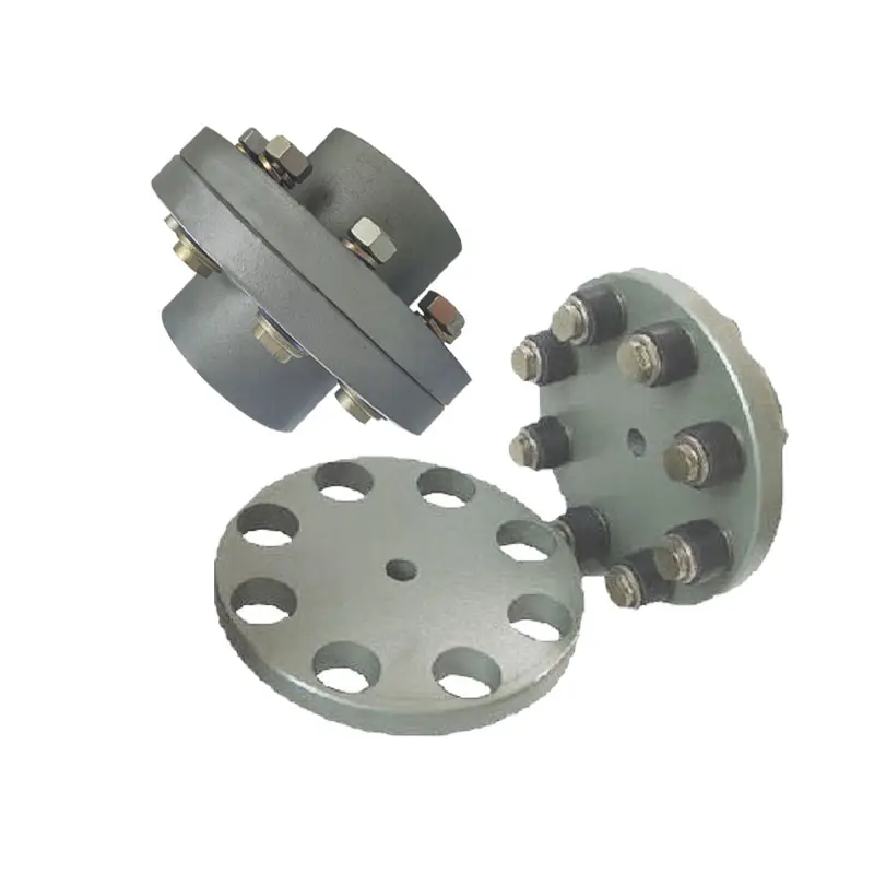
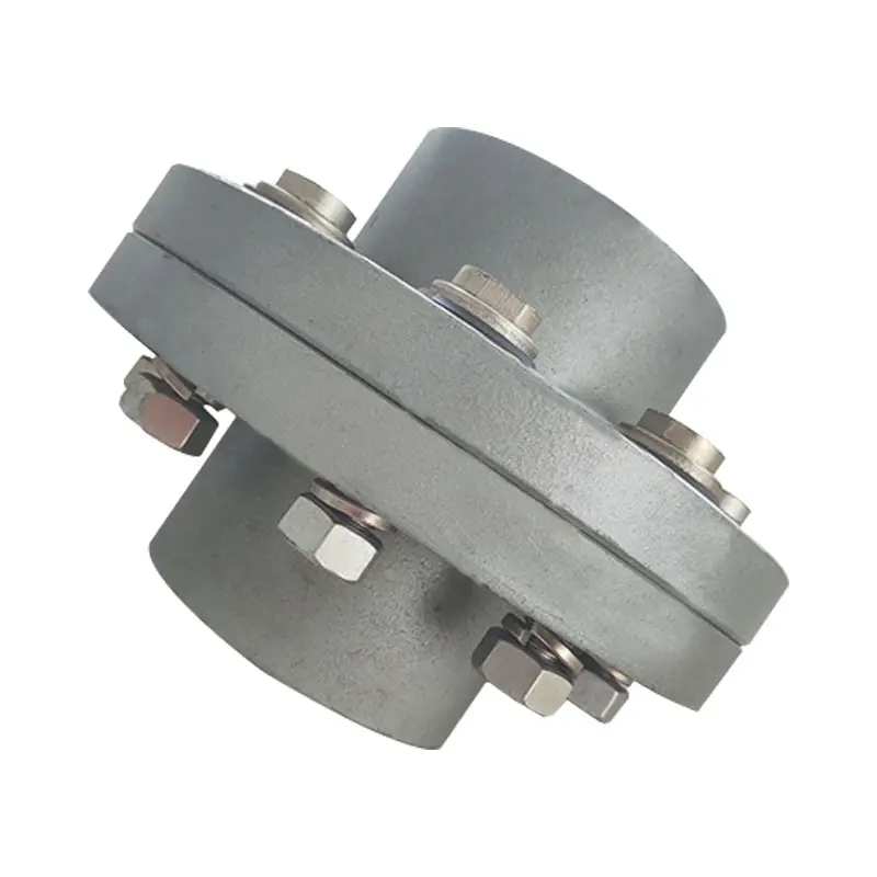
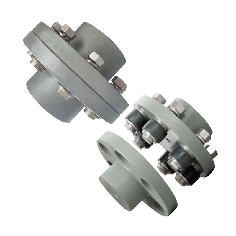
China manufacturer FM/UL Rigid or Flexible Couplings/Reducing Tee/Mechanical Tee/Elbow/Cross/Flange/Reducer/Cap/Grooved Pipe Fittings Grooved Couplings flange coupling
Product Description
Product Description
FM/UL Rigid or Flexible Couplings/Reducing Tee/Mechanical Tee/Elbow/Cross/Flange/Reducer/Cap/Grooved Pipe Fittings Grooved Couplings
FM/UL Rigid or Flexible Couplings/Reducing Tee/Mechanical Tee/Elbow/Cross/Flange/Reducer/Cap/Grooved Pipe Fittings Grooved Couplings
Ductile iron grooved pipe fittings and couplings (FM and UL approved) mainly including 2 kinds of grooved products:
(1) the pipe fittings function on connecting and sealing such as rigid coupling, flexible coupling, mechanical tee and grooved flange,
(2) the pipe fittings function on connecting and transition such as bend, tee, cross, reducer.
Specification
| Name | Rigid coupling, Flexible coupling, 90° Elbow, 45° Elbow, 22.5° Elbow, 11.25° Elbow, Split Flange, Adaptor Flange, Cap | |
| Tee, Reducing Tee(Grooved/Threaded), Mechnical Tee(Grooved/Threaded), U-bolted Mechnical Tee | ||
| Cross, Reducing Cross(Grooved/Threaded), Mechnical Cross(Grooved/Threaded) | ||
| Reducer(Grooved/Threaded), Grooved Eccentric Reducer | ||
| H.S. CODE | 735710000 | |
| Technology | Casting | |
| Connections | Grooved-Thread End, Grooved End | |
| Pressure Rate | 300PSI / 2.07MPa | |
| Size | 1” – 12” | |
| Pipe O.D. | 33.7MM – 323.9MM | |
| Surface Finish | Epoxy Powder,Painting,Galvanization,Dacromet (in Red/Orange/Blue/White Color) | |
| Design Standard | American Standard | ANSI/ASTM |
| European Standard | EN | |
| British Standard | BS | |
| Germany Standard | DIN | |
| Japanese Standard | JIS | |
| ISO Standard | ISO | |
| Thread Standard | ASME B.1.20.1 / EN15716 / DIN2999 / ISO7-1 / ISO228 / IS554 / BS EN15716 / BS 21.173 | |
| Material Standard | Ductile Iron confirms to ASTM A-536 Gr65-45-12,EN1563,JIS G5502,QT450-12 | |
| Gasket Material | EPDM,NBR or Silicon Rubber | |
| Bolts & Nuts | ISO 898-1class 8.8 | |
| Flanges Standard | PN series or Class series | |
| Packages | Plywood Cases or Plywood Pallets or Boxes | |
| Application | Fire Fighting System,Petrochemical & Gas Industry,Chemical,Machinery,Electric Power,Construction Water Works,Valve Industry,etc. | |
| Advantages | High Quality + Ready Stock + Faster Delivery + Customized | |
| Brand | LMP | |
| Certificate | ISO9001,API,CE,UL/FM | |
Company Profile
We are a leading manufacturer of pipe fittings and valves establised in 1996
1. We have over 20 years experience in exporting pipeline products.
2. 5 factories,complete 100+ projects every year.
3. Your 1 more good choice for better customer service.
Certifications
FAQ
What Industries Commonly Use Flange Couplings for Power Transmission?
Flange couplings are widely used in various industries for power transmission due to their reliability and versatility. Some of the common industries where flange couplings are employed include:
1. Manufacturing: In manufacturing industries such as automotive, aerospace, electronics, and consumer goods, flange couplings are utilized in machinery and equipment to transmit power between different components.
2. Oil and Gas: The oil and gas industry often uses flange couplings in pumps, compressors, and turbines for power transmission in exploration, extraction, and refining processes.
3. Chemical and Petrochemical: Flange couplings are used in various equipment within the chemical and petrochemical industry, including mixers, agitators, and pumps, to transfer power efficiently.
4. Mining and Construction: Heavy-duty machinery in mining and construction applications relies on flange couplings to transmit power in demanding and challenging environments.
5. Power Generation: Power plants, including thermal, hydroelectric, and wind power facilities, use flange couplings in turbines, generators, and auxiliary systems for power transmission.
6. Marine: In the marine industry, flange couplings are utilized in propulsion systems, winches, and other equipment that requires power transmission in marine vessels.
7. Steel and Metal Processing: Steel mills and metal processing plants use flange couplings in various equipment, including rolling mills and conveyor systems.
8. Food and Beverage: The food processing and beverage industry use flange couplings in mixers, pumps, and conveyor systems to handle power transmission in hygienic environments.
9. Pharmaceutical: Pharmaceutical manufacturing equipment employs flange couplings for power transmission in processes such as mixing, granulation, and tablet compression.
10. Water and Wastewater: Flange couplings are used in water treatment plants and wastewater facilities to transfer power in pumps and other equipment.
These are just a few examples, and flange couplings are found in many other industries where reliable power transmission is essential for smooth operations.
Can Flange Couplings Be Used in Applications with High Shock and Impact Loads?
Yes, flange couplings are designed to handle high shock and impact loads in various industrial applications. Their robust construction and rigid design make them suitable for use in systems where sudden shocks and impacts are common.
The ability of flange couplings to withstand shock and impact loads is influenced by several factors:
1. Material Selection: Flange couplings are often made from high-strength materials, such as alloy steels or stainless steels, which provide excellent toughness and resistance to impact loads.
2. Robust Design: The design of flange couplings typically includes features like sturdy flanges and high-strength bolts that enhance their ability to withstand shocks and impacts.
3. Tolerance for Misalignment: Some flange couplings, such as flexible flange couplings, have the ability to accommodate slight misalignments between shafts. This flexibility helps absorb shocks and vibrations, reducing the impact on connected equipment.
4. Proper Installation: Proper installation and alignment are crucial for ensuring that flange couplings can handle shock and impact loads effectively. Precision alignment and the correct torque on the bolts prevent premature failures due to misalignment.
5. Application Considerations: When selecting a flange coupling for an application with high shock and impact loads, factors such as torque requirements, rotational speed, and the magnitude of the shock should be taken into account to choose the most suitable coupling type and size.
Overall, flange couplings are a reliable choice for systems where shock and impact loads are present. However, it is essential to consult with coupling manufacturers or engineering experts to ensure the proper selection and installation of the coupling for specific high-impact applications.
Advantages of Flange Couplings in Mechanical Systems
Flange couplings offer several advantages in mechanical systems, making them a popular choice for connecting shafts in various applications:
- High Torque Transmission: Flange couplings provide a rigid and secure connection between shafts, allowing for efficient transmission of high torque without slippage or power loss.
- Precise Alignment: Proper alignment of flange couplings ensures that the connected shafts are in perfect axial alignment, reducing the risk of excessive bearing loads and increasing the longevity of the machinery.
- Zero Backlash: Flange couplings have no play or free movement between the shafts, resulting in immediate torque transmission and precise motion control, especially in applications requiring precise positioning.
- Robust and Durable: Flange couplings are typically made from high-quality materials such as steel, cast iron, or aluminum, providing excellent durability and resistance to wear and corrosion.
- Wide Range of Sizes and Torque Capacities: Flange couplings are available in various sizes and configurations, allowing them to be used in a wide range of applications with different torque requirements.
- Simple Installation: Installing flange couplings is relatively straightforward, requiring alignment and fastening of the flanges with bolts and nuts.
- Wide Application Range: Flange couplings are used in various industries, including heavy machinery, pumps, compressors, marine propulsion, and power generation equipment.
- Suitable for High-Speed Applications: Flange couplings can handle high rotational speeds, making them suitable for applications requiring high-speed power transmission.
- Minimal Maintenance: Once properly installed, flange couplings require minimal maintenance, reducing downtime and operational costs.
Despite their advantages, flange couplings also have some limitations. They lack the ability to compensate for misalignment like flexible couplings, which can lead to increased stress on bearings and other components if not correctly aligned. Additionally, the rigid nature of flange couplings means they may not be suitable for applications where shaft misalignment is common or where shock and vibration absorption is required.
Overall, flange couplings are a reliable and robust choice for mechanical systems, particularly in applications demanding high torque transmission and precise shaft alignment. Proper installation and maintenance are crucial to ensure optimal performance and longevity of both the coupling and the connected machinery.
editor by CX 2023-10-06
China manufacturer Stainless Steel Coupling Gear Rigid Roller Chain Fluid Tyre Grid Jaw Spider HRC Nm Motor Flange Gear Pump Rubber Spline Shaft Flexible Universal Joint Coupling flange coupling
Product Description
Stainless Steel Coupling Gear Rigid Roller Chain Fluid Tyre Grid Jaw Spider HRC Nm Motor Flange Gear Pump Rubber Spline Shaft Flexible Universal Joint Coupling
Product Description
Main products
Coupling refers to a device that connects 2 shafts or shafts and rotating parts, rotates together during the transmission of motion and power, and does not disengage under normal conditions. Sometimes it is also used as a safety device to prevent the connected parts from bearing excessive load, which plays the role of overload protection.
Couplings can be divided into rigid couplings and flexible couplings.
Rigid couplings do not have buffering property and the ability to compensate the relative displacement of 2 axes. It is required that the 2 axes be strictly aligned. However, such couplings are simple in structure, low in manufacturing cost, convenient in assembly and disassembly, and maintenance, which can ensure that the 2 axes are relatively neutral, have large transmission torque, and are widely used. Commonly used are flange coupling, sleeve coupling and jacket coupling.
Flexible coupling can also be divided into flexible coupling without elastic element and flexible coupling with elastic element. The former type only has the ability to compensate the relative displacement of 2 axes, but cannot cushion and reduce vibration. Common types include slider coupling, gear coupling, universal coupling and chain coupling; The latter type contains elastic elements. In addition to the ability to compensate the relative displacement of 2 axes, it also has the functions of buffering and vibration reduction. However, due to the strength of elastic elements, the transmitted torque is generally inferior to that of flexible couplings without elastic elements. Common types include elastic sleeve pin couplings, elastic pin couplings, quincunx couplings, tire type couplings, serpentine spring couplings, spring couplings, etc
Coupling performance
1) Mobility. The movability of the coupling refers to the ability to compensate the relative displacement of 2 rotating components. Factors such as manufacturing and installation errors between connected components, temperature changes during operation and deformation under load all put CZPT requirements for mobility. The movable performance compensates or alleviates the additional load between shafts, bearings, couplings and other components caused by the relative displacement between rotating components.
(2) Buffering. For the occasions where the load is often started or the working load changes, the coupling shall be equipped with elastic elements that play the role of cushioning and vibration reduction to protect the prime mover and the working machine from little or no damage.
(3) Safe, reliable, with sufficient strength and service life.
(4) Simple structure, easy to assemble, disassemble and maintain.
How to select the appropriate coupling type
The following items should be considered when selecting the coupling type.
1. The size and nature of the required transmission torque, the requirements for buffering and damping functions, and whether resonance may occur.
2. The relative displacement of the axes of the 2 shafts is caused by manufacturing and assembly errors, shaft load and thermal expansion deformation, and relative movement between components.
3. Permissible overall dimensions and installation methods, and necessary operating space for assembly, adjustment and maintenance. For large couplings, they should be able to be disassembled without axial movement of the shaft.
In addition, the working environment, service life, lubrication, sealing, economy and other conditions should also be considered, and a suitable coupling type should be selected by referring to the characteristics of various couplings.
If you cannot determine the type, you can contact our professional engineer
Related products
Company Profile
Our Equipments
Main production equipment:
Large lathe, surface grinder, milling machine, gear shaper, spline milling machine, horizontal broaching machine, gear hobbing machine, shaper, slotting machine, bench drilling machine, radial drilling machine, boring machine, band sawing machine, horizontal lathe, end milling machine, crankshaft grinder, CNC milling machine, casting equipment, etc.
Inspection equipment:
Dynamic balance tester, high-speed intelligent carbon and sulfur analyzer, Blochon optical hardness tester, Leeb hardness tester, magnetic yoke flaw detector, special detection, modular fixture (self-made), etc.
Machining equipments
Heat equipment
Our Factory
Application – Photos from our partner customers
Company Profile
Our leading products are mechanical transmission basic parts – couplings, mainly including universal couplings, drum gear couplings, elastic couplings and other 3 categories of more than 30 series of varieties. It is widely used in metallurgical steel rolling, wind power, hydropower, mining, engineering machinery, petrochemical, lifting, paper making, rubber, rail transit, shipbuilding and marine engineering and other industries.
Our factory takes the basic parts of national standards as the benchmark, has more than 40 years of coupling production experience, takes “scientific management, pioneering and innovation, ensuring quality and customer satisfaction” as the quality policy, and aims to continuously provide users with satisfactory products and services. The production is guided by reasonable process, and the ISO9001:2015 quality management system standard is strictly implemented. We adhere to the principle of continuous improvement and innovation of coupling products. In recent years, it has successfully developed 10 national patent products such as SWF cross shaft universal coupling, among which the double cross shaft universal joint has won the national invention patent, SWF cross shaft universal coupling has won the new product award of China’s general mechanical parts coupling industry and the ZHangZhoug Province new product science and technology project.
Our factory has strong technical force, excellent process equipment, complete professional production equipment, perfect detection means, excellent after-sales service, various products and complete specifications. At the same time, we can provide the design and manufacturing of special non-standard products according to the needs of users. Our products sell well at home and abroad, and are trusted by the majority of users. We sincerely welcome friends from all walks of life at home and abroad to visit and negotiate for common development.p

Impact of Flange Coupling on Noise and Vibration in a Mechanical System
Flange couplings play a significant role in the overall noise and vibration levels of a mechanical system. The type of flange coupling used and its design characteristics can have varying effects on the system’s noise and vibration. Let’s explore how flange couplings impact noise and vibration in a mechanical system:
1. Rigid Flange Couplings:
Rigid flange couplings, being solid and inflexible connections, are generally considered to be more rigid than flexible couplings. As a result, they can transmit vibrations more directly between the connected shafts and the rest of the system. The lack of misalignment compensation can lead to higher stress on the bearings and other components, contributing to increased vibration levels.
However, rigid flange couplings are also less likely to introduce any additional sources of vibration due to their simple and solid construction. If the system is well-aligned and requires no misalignment compensation, rigid flange couplings can provide a stable and reliable connection.
2. Flexible Flange Couplings:
Flexible flange couplings are designed to dampen vibrations and shocks in the system. The flexibility of these couplings allows them to absorb and minimize the transmission of vibrations between the connected shafts and the rest of the system. As a result, flexible flange couplings can reduce overall vibration levels and provide a smoother and quieter operation.
Additionally, the misalignment compensation capability of flexible flange couplings helps to reduce stress on the bearings and other components. By accommodating misalignment, these couplings prevent the system from experiencing excessive vibrations that can lead to premature wear and failures.
Overall Impact:
The choice of flange coupling design will significantly influence the noise and vibration levels in the mechanical system. In applications where precise alignment is crucial, rigid flange couplings may be preferred despite potentially higher vibration levels. On the other hand, flexible flange couplings are ideal for systems where misalignment is expected or where vibration dampening is a priority.
It’s important to consider the specific requirements of the application when selecting a flange coupling. Factors such as torque capacity, operating conditions, alignment needs, and desired noise and vibration levels should all be taken into account. Proper installation and maintenance of the chosen flange coupling can also impact its performance in reducing noise and vibration levels in the mechanical system.

Flange Couplings in Precision Motion Control Systems
Yes, flange couplings can be used in precision motion control systems, provided they are designed and selected appropriately for the specific application. Precision motion control systems often require high accuracy, repeatability, and minimal backlash. Flange couplings can meet these requirements when certain factors are considered:
1. Backlash: Precision motion control systems require minimal or zero backlash to ensure accurate positioning. Flexible flange couplings with no metal-to-metal contact, such as elastomeric or beam couplings, are preferred for these applications.
2. Rigidity: Flange couplings should have sufficient torsional rigidity to maintain the accuracy of the motion system. Rigid flange couplings made from materials like aluminum or steel can provide higher torsional stiffness.
3. Misalignment Compensation: In precision systems, alignment errors must be minimized. Flexible flange couplings can compensate for minor misalignments between shafts while maintaining precise motion transmission.
4. Low Inertia: Flange couplings with low inertia are desirable as they reduce the overall inertia of the system, enabling faster acceleration and deceleration during motion.
5. Material Selection: The choice of material is critical in precision motion control applications. Materials with high strength-to-weight ratios and minimal deformation under load are preferred.
6. Environmental Factors: Consider the environmental conditions in which the flange coupling will operate. For instance, in vacuum environments or cleanrooms, non-lubricated or special coatings may be necessary.
When selecting a flange coupling for precision motion control systems, it’s essential to consider the specific requirements of the application, including speed, torque, misalignment, and environmental factors. Regular maintenance and periodic checks for wear and misalignment are crucial to ensure the continued performance and accuracy of the motion control system.

Can Flange Couplings Accommodate High Torque and High-Speed Applications?
Yes, flange couplings are designed to accommodate both high torque and high-speed applications. They are capable of transmitting significant amounts of torque between shafts while maintaining stable and efficient power transmission. The ability to handle high torque and high-speed applications depends on various factors, including the design, material, and size of the flange coupling.
1. Design: Flange couplings are available in different designs, such as rigid flange couplings and flexible flange couplings. Rigid flange couplings are more suitable for applications that require precise shaft alignment and minimal misalignment. On the other hand, flexible flange couplings can accommodate slight misalignments and are suitable for applications where shock or vibration may occur. The design of the coupling is crucial in determining its torque and speed capabilities.
2. Material: Flange couplings are manufactured from various materials, including steel, stainless steel, aluminum, and other alloys. The material selection is essential in determining the coupling’s strength, durability, and resistance to wear and fatigue. High-quality materials are used in flange couplings for high torque and high-speed applications to ensure their reliability and performance.
3. Size and Dimensions: The size and dimensions of the flange coupling play a significant role in determining its torque and speed ratings. Larger flange couplings with increased diameter and thickness can handle higher torque and speed compared to smaller couplings. It is essential to choose the appropriate size of the coupling based on the application’s torque and speed requirements.
4. Surface Finish: The surface finish of the flange coupling is critical, especially in high-speed applications. A smooth surface finish reduces friction and wear between the mating surfaces of the flanges, bolts, and nuts, thereby improving the overall efficiency of the coupling.
5. Lubrication: Proper lubrication is essential for flange couplings in high-speed and high-torque applications. Lubricants help reduce friction and wear, dissipate heat, and prevent premature failure of the coupling components.
6. Manufacturer’s Recommendations: It is crucial to follow the manufacturer’s recommendations and guidelines regarding the maximum torque and speed ratings of the flange coupling. Exceeding the recommended limits can lead to coupling failure and potential damage to the connected equipment.
In conclusion, flange couplings can be effectively used in high torque and high-speed applications when selected and maintained properly. Choosing the right design, material, size, and adhering to the manufacturer’s guidelines ensures that the flange coupling can handle the required torque and rotational speed efficiently and reliably.
editor by CX 2023-08-21
China Professional Flange Cast Iron Coupling Steel Universal Joint Cardan Pump Rubber Motor Disc Curved Tooth Flex Rigid Drive Shaft Nm Yox Fluid Jaw Flexible Chain Gear Couplings flange coupling
Product Description
Excellent powder metallurgy parts metallic sintered parts
We could offer various powder metallurgy parts including iron based and copper based with top quality and cheapest price, please only send the drawing or sample to us, we will according to customer’s requirement to make it. if you are interested in our product, please do not hesitate to contact us, we would like to offer the top quality and best service for you. thank you!
How do We Work with Our Clients
1. For a design expert or a big company with your own engineering team: we prefer to receive a fully RFQ pack from you including drawing, 3D model, quantity, pictures;
2. For a start-up company owner or green hand for engineering: just send an idea that you want to try, you don’t even need to know what casting is;
3. Our sales will reply you within 24 hours to confirm further details and give the estimated quote time;
4. Our engineering team will evaluate your inquiry and provide our offer within next 1~3 working days.
5. We can arrange a technical communication meeting with you and our engineers together anytime if required.
| Place of origin: | Jangsu,China |
| Type: | Powder metallurgy sintering |
| Spare parts type: | Powder metallurgy parts |
| Machinery Test report: | Provided |
| Material: | Iron,stainless,steel,copper |
| Key selling points: | Quality assurance |
| Mould type: | Tungsten steel |
| Material standard: | MPIF 35,DIN 3571,JIS Z 2550 |
| Application: | Small home appliances,Lockset,Electric tool, automobile, |
| Brand Name: | OEM SERVICE |
| Plating: | Customized |
| After-sales Service: | Online support |
| Processing: | Powder Metallurgr,CNC Machining |
| Powder Metallurgr: | High frequency quenching, oil immersion |
| Quality Control: | 100% inspection |
The Advantage of Powder Metallurgy Process
1. Cost effective
The final products can be compacted with powder metallurgy method ,and no need or can shorten the processing of machine .It can save material greatly and reduce the production cost .
2. Complex shapes
Powder metallurgy allows to obtain complex shapes directly from the compacting tooling ,without any machining operation ,like teeth ,splines ,profiles ,frontal geometries etc.
3. High precision
Achievable tolerances in the perpendicular direction of compacting are typically IT 8-9 as sintered,improvable up to IT 5-7 after sizing .Additional machining operations can improve the precision .
4. Self-lubrication
The interconnected porosity of the material can be filled with oils ,obtaining then a self-lubricating bearing :the oil provides constant lubrication between bearing and shaft ,and the system does not need any additional external lubricant .
5. Green technology
The manufacturing process of sintered components is certified as ecological ,because the material waste is very low ,the product is recyclable ,and the energy efficiency is good because the material is not molten.
FAQ
Q1: What is the type of payment?
A: Usually you should prepay 50% of the total amount. The balance should be pay off before shipment.
Q2: How to guarantee the high quality?
A: 100% inspection. We have Carl Zeiss high-precision testing equipment and testing department to make sure every product of size,appearance and pressure test are good.
Q3: How long will you give me the reply?
A: we will contact you in 12 hours as soon as we can.
Q4. How about your delivery time?
A: Generally, it will take 25 to 35 days after receiving your advance payment. The specific delivery time depends on the items and the quantity of your order. and if the item was non standard, we have to consider extra 10-15days for tooling/mould made.
Q5. Can you produce according to the samples or drawings?
A: Yes, we can produce by your samples or technical drawings. We can build the molds and fixtures.
Q6: How about tooling Charge?
A: Tooling charge only charge once when first order, all future orders would not charge again even tooling repair or under maintance.
Q7: What is your sample policy?
A: We can supply the sample if we have ready parts in stock, but the customers have to pay the sample cost and the courier cost.
Q8: How do you make our business long-term and good relationship?
A: 1. We keep good quality and competitive price to ensure our customers benefit ;
2. We respect every customer as our friend and we sincerely do business and make friends with them, no matter where they come from.
Torque and Speed Ratings of Flange Couplings
Flange couplings are available in various sizes and designs to accommodate a wide range of torque and rotational speed requirements. The torque and speed ratings of flange couplings depend on several factors, including their size, material, and design.
Torque Rating:
The torque rating of a flange coupling indicates the maximum amount of torque it can transmit without experiencing failure or damage. It is typically specified in Nm (Newton-meters) or lb-ft (pound-feet). The torque rating varies for different sizes and types of flange couplings. Larger flange couplings generally have higher torque ratings compared to smaller ones.
Speed Rating:
The speed rating of a flange coupling represents the maximum rotational speed at which it can operate reliably without excessive vibration or wear. It is typically expressed in RPM (revolutions per minute). The speed rating is influenced by factors such as the design, material, and balancing of the flange coupling. Higher-speed applications require flange couplings that can handle the increased centrifugal forces and dynamic loads associated with higher RPMs.
Size and Type:
The torque and speed ratings vary for different sizes and types of flange couplings. For example:
- Smaller flange couplings, such as those used in light-duty applications, may have torque ratings ranging from a few Nm to several hundred Nm, and speed ratings up to a few thousand RPM.
- Larger flange couplings, used in heavy-duty industrial applications, can have torque ratings exceeding several thousand Nm and speed ratings that may reach tens of thousands of RPM.
- Flexible flange couplings may have slightly lower torque ratings compared to rigid flange couplings but offer greater misalignment compensation.
Manufacturer Specifications:
It is essential to refer to the manufacturer’s specifications and technical data to determine the specific torque and speed ratings for each size and type of flange coupling. Manufacturers typically provide detailed performance data to help users select the appropriate flange coupling for their specific application.
Application Considerations:
When selecting a flange coupling, it is crucial to consider the torque and speed requirements of the application. The operating conditions, such as load fluctuations and thermal effects, should also be taken into account to ensure the flange coupling’s reliable performance and longevity.
Conclusion:
Flange couplings come in various sizes and designs, each with its own torque and speed ratings. Properly selecting a flange coupling that meets the specific torque and speed requirements of the application is essential to ensure efficient and trouble-free power transmission in mechanical systems.
Key Features to Consider When Purchasing a Flange Coupling
When purchasing a flange coupling, it is essential to consider several key features to ensure it meets the specific requirements of your application. Here are the main factors to look for:
- Type of Flange Coupling: There are various types of flange couplings, such as rigid, flexible, and fluid couplings. Choose the type that best suits your application’s needs, considering factors like misalignment compensation, torsional stiffness, and vibration damping.
- Size and Dimensions: Select the flange coupling with the appropriate size and dimensions to fit your shafts and equipment. Consider shaft diameter, coupling length, and any space limitations.
- Material: Flange couplings can be made from various materials, including steel, aluminum, stainless steel, and elastomers. Choose a material that offers the required strength, corrosion resistance, and durability for your operating conditions.
- Torsional Rating: Check the torsional rating of the flange coupling to ensure it can handle the torque requirements of your application without failure or deformation.
- Misalignment Compensation: If your application experiences shaft misalignment, opt for a flexible flange coupling that can accommodate angular, parallel, and axial misalignment to prevent stress on connected equipment.
- Backlash: For precision applications, select a flange coupling with minimal or no backlash to maintain accurate positioning and reduce the effects of mechanical play.
- Operating Speed: Consider the operating speed range of the flange coupling to ensure it can handle the rotational speed requirements without issues like resonance or fatigue.
- Environmental Compatibility: Evaluate the flange coupling’s ability to withstand the environmental conditions of your application, such as temperature, humidity, and exposure to chemicals or corrosive substances.
- Installation and Maintenance: Choose a flange coupling that is easy to install and maintain, as proper installation and periodic maintenance are crucial for optimal performance and longevity.
- Cost and Value: Compare the cost of the flange coupling with its features and performance to ensure you are getting the best value for your investment.
By carefully considering these key features, you can select a flange coupling that not only meets the demands of your application but also ensures reliable and efficient power transmission while minimizing downtime and maintenance costs.
What is a flange coupling and how does it work?
A flange coupling is a type of rigid coupling used to connect two shafts together in a mechanical system. It consists of two flanges, one on each shaft, which are bolted together to form a solid and robust connection. Flange couplings are widely used in applications where precise alignment, high torque transmission, and zero backlash are critical.
The key components of a flange coupling include:
- Flanges: The flanges are circular discs with holes around the perimeter for bolting them to the respective shaft ends. The flanges are made from materials such as steel, cast iron, or aluminum, depending on the application requirements.
- Fasteners: High-strength bolts or studs with nuts are used to fasten the flanges together securely. The number and size of the bolts depend on the size and torque capacity of the coupling.
- Gaskets: In some cases, gaskets or spacers are used between the flanges to provide insulation, prevent corrosion, or compensate for any slight misalignments between the shafts.
How a flange coupling works:
- The two shafts that need to be connected are brought together with their respective flanges facing each other.
- The flanges are aligned precisely to ensure that both shafts are in perfect axial alignment. Proper alignment is essential to prevent excessive loads on the bearings and to ensure efficient torque transmission.
- Once the flanges are aligned, high-strength bolts or studs are inserted through the holes in the flanges, and nuts are fastened tightly to hold the flanges together securely.
- The tight connection between the flanges creates a rigid joint between the shafts, allowing torque to be transmitted from one shaft to the other with minimal losses.
- Flange couplings are designed to have zero backlash, meaning there is no play or free movement between the shafts when the direction of rotation changes. This feature ensures precise and immediate power transmission between the connected shafts.
Flange couplings are commonly used in various industrial applications, including heavy machinery, pumps, compressors, and marine propulsion systems. They are preferred when a reliable, high-torque transmission with precise alignment is required. However, they do not offer flexibility to accommodate misalignment, which is a limitation compared to flexible couplings. Therefore, proper alignment during installation is critical to avoid premature wear and failure of the coupling and connected equipment.
editor by CX 2023-08-02
China OEM Rigid Stainless Steel Grooved Fitting Couplings Ruixuan Manufacture dc coupling
Product Description
Product Description
Steel flexible joint is also called clamp, open expansion joint, steel flexible pipe joint. Steel flexible joint is a kind of pipe connection, reliable performance, easy to install products. At low pressure, by the elastic deformation of the sealing ring, to achieve the purpose of sealing; When the pressure increases, the medium acts on the sealing ring to play the role of self-sealing, and there is a gap between the pipe ends to compensate for the displacement and deflection of the pipe caused by thermal expansion and cold contraction.
The working temperature of the clamp joint is generally -30ºC-+130ºC. The medium property is weak acid, weak alkali and lubricating oil range can be applied. If beyond the above range can also provide our company with the nature of the medium parameters or optional parameters or optional specified rubber ring material. In addition to the connection function, the joint can also provide compensation, withstand axial force, provide Angle, reduce vibration wave, adapt to the change of foundation.
The advantages of clamp joint:
1 Clamp joint has good continuity, will not produce distortion, easy to achieve the ideal laying state.
2 Clamp pipe joint in a free state, do not bear the weight of the pipe, not subjected to external shear, especially DN200 pipe diameter, more must consider the weight of the pipe.
3. It is easy to keep the coaxial position when installing the clamp joint to ensure the uneven distribution of the radial clearance between the inner diameter of the pipe clamp and the outer diameter of the pipe. The rubber ring will be deformed under high pressure due to the large local clearance, which will affect the sealing effect and even destroy the rubber ring.
4. It is suitable for the application in the subsidence zone, which can reduce the Angle between the pipe segments caused by the subsidence of the support pier.
5 is conducive to pipeline maintenance. Turn the pipe, save labor and effort when changing the pipe.
Detailed Photos
Product Parameters
PN1.6/2.5/4.0/6.4MPa KRHD
| DN(mm) | Dw(mm) | Allowable Angle Φ |
Installation length L (mm) |
Maximal length (mm) |
Fitting bolt d×L (mm) |
| 80 | 89 | 17.90 | 100 | 110 | M12*60 |
| 100 | 108 | 15.06 | 100 | 110 | M14*60 |
| 125 | 133 | 13.05 | 105 | 115 | M14*60 |
| 150 | 159 | 12.09 | 110 | 120 | M14*60 |
| 175 | 194 | 10.51 | 110 | 120 | M16*60 |
| 200 | 219 | 9.33 | 116 | 126 | M16*75 |
| 225 | 245 | 8.36 | 122 | 132 | M16*80 |
| 250 | 273 | 7.51 | 127 | 137 | M18*90 |
| 300 | 325 | 6.32 | 130 | 140 | M18*100 |
| 350 | 377 | 5.45 | 135 | 145 | M18*100 |
| 400 | 426 | 4.80 | 140 | 150 | M18*110 |
| 450 | 480 | 4.28 | 145 | 155 | M18*110 |
| 500 | 530 | 3.88 | 150 | 160 | M18*120 |
| 600 | 630 | 3.27 | 155 | 165 | M18*120 |
| 700 | 720 | 2.86 | 160 | 170 | M20*120 |
| 800 | 820 | 2.51 | 165 | 175 | M20*130 |
| 900 | 920 | 2.24 | 170 | 180 | M20*130 |
| 1000 | 1571 | 2.02 | 175 | 185 | M20*130 |
| 1200 | 1220 | 1.69 | 180 | 190 | M22*140 |
| 1400 | 1420 | 1.45 | 185 | 195 | M22*140 |
| 1600 | 1620 | 1.27 | 190 | 200 | M22*140 |
| 1800 | 1820 | 1.13 | 195 | 205 | M22*150 |
| 2000 | 2571 | 1.01 | 200 | 210 | M24*150 |
| 2200 | 2571 | 1.01 | 205 | 215 | M24*150 |
| 2400 | 2420 | 1.01 | 210 | 220 | M24*150 |
| 2600 | 2620 | 1.01 | 215 | 225 | M24*160 |
| 2800 | 2830 | 1.01 | 220 | 230 | M27*160 |
| 3000 | 3571 | 1.01 | 225 | 230 | M27*160 |
| 3200 | 3220 | 1.01 | 230 | 240 | M27*180 |
Datas above are only for reference,if you want to know more details, please click here to contact us.
Installation Instructions
1. Prepare groove pipe sections, fittings and accessories that meet the requirements.
2. Check whether the rubber sealing ring is damaged and put it on the end of a steel pipe.
3. There should be a certain gap between the end and both ends of the steel pipe close to the end and both ends of the pipe which has been covered with rubber sealing ring. The clearance shall meet the standard requirements.
4. Put the rubber seal ring on the end of another steel pipe, make the rubber seal ring in the middle of the interface, and apply lubricant on the same side.
5. Check the axis of the pipe.
6. Install upper and lower clamps on the outer side of rubber seal-ing ring at the interface position, and clip the collar convex edge into the groove.
7. Press the upper and lower clamp ears with hand force, tighten the collar of the clamp with a wooden hammer, and tighten the upper and lower clamps tightly.
8. At the clamp screw hole position, put on the studs and tighten the nuts evenly to prevent the rubber sealing ring from wrin-kling.
9. check and comfirm that the collar convex edge is clamped into the groove.
products application
Company Profile
HangZhou Ruixuan pipeline equipment factory was founded in 1996.It is an excellent enterprise specializing in manufacturing and selling pipe fittings.It’s located in Xicun village ,HangZhou city,ZheJiang province ,the concentrated area of pipeline equipment industry in China.The company factory is located in Xicun town pipeline equipment industrial park.It covered an area of20000 square meters.
At present, the company has the production capacity of pipeline equipment with a maximum diameter of 4000mm, and its main products are: Steel expansion joint, flexible waterproof sleeve, large diameter flange, double flange force transfer expansion joint, large deflection loose sleeve compensation joint, spherical compensation joint, sleeve compensator, bellows compensator, non-metallic compensator, rubber expansion joint, DC medium no thrust sleeve compensator, flexible expansion pipe and other pipeline equipment. The annual production capacity is 30 million sets.
The flexible telescopic pipe equipment is mainly used in the pipeline crossing different geological structures under different conditions and the application of pipe installation drop, reduce or avoid the impact of geological settlement and crustal activity on the pipeline, so that the construction unit can save more than 50% of the cost when purchasing the equipment. The rubber expansion joint series products of the company, the maximum production diameter of 3600mm, have been applied in millions of units of thermal power projects in China for many times, and have been praised by the users.
The company passed ISO9001:2008 quality management system certification in 2009 and ISO14000:2004 environmental management system certification in 2009. The company has a strict quality control system, standard production process, standard factory inspection hand section, to ensure that every product meets the national standards and customer requirements.
Business philosophy: responsible production of products, return the trust of customers; To build a community with a sense of belonging and appreciate employees’ contributions; Make a contribution to the society of enterprises, give back to the good times. HangZhou Ruixuan pipeline equipment factory is willing to work with friends from all walks of life hand in hand, mutual support, create a better future!
Certifications
FAQ
Q:Can you make the product as per client’s requirement?
A:Yes, we can make it with your exact requirement.
Q:What are your payment terms?
A:T/T (30% as deposit, the rest 70% will be paid before delivery), L/C at sight.
Q:Where is your nearest loading port?
A:ZheJiang , HangZhou or ZheJiang , China.
Q:How can you guarantee the quality or any warranty?
A:If any quality problems during use, all the products can be returned or according to consumer’s requests.
Q:Do you accept small quantity order?
A:Of course we do.
Q:And what is your shipment and delivery time?
A:By sea or air. Normally 7 to 14 Days for delivery, according to your order quantity.
|
Shipping Cost:
Estimated freight per unit. |
To be negotiated |
|---|
| Application: | Fire Fighting |
|---|---|
| Feature: | Corrosion Resistant |
| Material: | Ductile Iron |
| Samples: |
US$ 6.5/Piece
1 Piece(Min.Order) | Order Sample |
|---|
| Customization: |
Available
| Customized Request |
|---|

What Is a Coupling?
A coupling is a device used to connect two shafts. It transmits power between them and allows for some misalignment or end movement. There are several types of couplings. The most common ones are gear couplings and planetary couplings. However, there are many others as well.
Transfer of energy
Energy coupling is a process by which two biological reactions are linked by sharing energy. The energy released during one reaction can be used to drive the second. It is a very useful mechanism that synchronizes two biological systems. All cells have two types of reactions, exergonic and endergonic, and they are connected through energy coupling.
This process is important for a number of reasons. The first is that it allows the exchange of electrons and their energy. In a single molecule, this energy transfer involves the exchange of two electrons of different energy and spin. This exchange occurs because of the overlap interaction of two MOs.
Secondly, it is possible to achieve quadratic coupling. This is a phenomenon that occurs in circular membrane resonators when the system is statically deflected. This phenomenon has been gaining a great deal of interest as a mechanism for stronger coupling. If this mechanism is employed in a physical system, energy can be transferred on a nanometer scale.
The magnetic field is another important factor that affects the exchange of energy between semiconductor QWs. A strong magnetic field controls the strength of the coupling and the energy order of the exciton. The magnetic field can also influence the direction of polariton-mediated energy transfer. This mechanism is very promising for controlling the routing of excitation in a semiconductor.
Functions
Couplings play a variety of functions, including transferring power, compensating for misalignment, and absorbing shock. These functions depend on the type of shaft being coupled. There are four basic types: angular, parallel, and symmetrical. In many cases, coupling is necessary to accommodate misalignment.
Couplings are mechanical devices that join two rotating pieces of equipment. They are used to transfer power and allow for a small degree of end-to-end misalignment. This allows them to be used in many different applications, such as the transmission from the gearbox to the differential in an automobile. In addition, couplings can be used to transfer power to spindles.
Types
There are two main types of couplings: rigid and flexible. Rigid couplings are designed to prevent relative motion between the two shafts and are suitable for applications where precise alignment is required. However, high stresses in the case of significant misalignment can cause early failure of the coupling. Flexible couplings, on the other hand, allow for misalignment and allow for torque transmission.
A software application may exhibit different types of coupling. The first type involves the use of data. This means that one module may use data from another module for its operation. A good example of data coupling is the inheritance of an object. In a software application, one module can use another module’s data and parameters.
Another type of coupling is a rigid sleeve coupling. This type of coupling has a pipe with a bore that is finished to a specified tolerance. The pipe contains two threaded holes for transmitting torque. The sleeve is secured by a gib head key. This type of coupling may be used in applications where a couple of shafts are close together.
Other types of coupling include common and external. Common coupling occurs when two modules share global data and communication protocols. This type of coupling can lead to uncontrollable error propagation and unforeseen side effects when changes are made to the system. External coupling, on the other hand, involves two modules sharing an external device interface or communication protocol. Both types of coupling involve a shared code structure and depend on the external modules or hardware.
Mechanical couplings are essential in power transmission. They connect rotating shafts and can either be rigid or flexible, depending on the accuracy required. These couplings are used in pumps, compressors, motors, and generators to transmit power and torque. In addition to transferring power, couplings can also prevent torque overload.
Applications
Different coupling styles are ideal for different applications, and they have different characteristics that influence the coupling’s reliability during operation. These characteristics include stiffness, misalignment capability, ease of installation and maintenance, inherent balance, and speed capability. Selecting the right coupling style for a particular application is essential to minimize performance problems and maximize utility.
It is important to know the requirements for the coupling you choose before you start shopping. A proper selection process takes into account several design criteria, including torque and rpm, acoustic signals, and environmental factors. Once you’ve identified these parameters, you can select the best coupling for the job.
A gear coupling provides a mechanical connection between two rotating shafts. These couplings use gear mesh to transmit torque and power between two shafts. They’re typically used on large industrial machines, but they can also be used in smaller motion control systems. In smaller systems, a zero-backlash coupling design is ideal.
Another type of coupling is the flange coupling. These are easy to manufacture. Their design is similar to a sleeve coupling. But unlike a sleeve coupling, a flange coupling features a keyway on one side and two threaded holes on the other. These couplings are used in medium-duty industrial applications.
Besides being useful for power transmission, couplings can also prevent machine vibration. If vibration occurs in a machine, it can cause it to deviate from its predetermined position, or damage the motor. Couplings, however, help prevent this by absorbing the vibration and shock and preventing damage to expensive parts.
Couplings are heavily used in the industrial machinery and electrical industries. They provide the necessary rotation mechanism required by machinery and other equipment. Coupling suppliers can help customers find the right coupling for a specific application.
Criteria for selecting a coupling
When selecting a coupling for a specific application, there are a number of different factors to consider. These factors vary greatly, as do operating conditions, so selecting the best coupling for your system can be challenging. Some of these factors include horsepower, torque, and speed. You also need to consider the size of the shafts and the geometry of the equipment. Space restrictions and maintenance and installation requirements should also be taken into account. Other considerations can be specific to your system, such as the need for reversing.
First, determine what size coupling you need. The coupling’s size should be able to handle the torque required by the application. In addition, determine the interface connection, such as straight or tapered keyed shafts. Some couplings also feature integral flange connections.
During the specification process, be sure to specify which materials the coupling will be made of. This is important because the material will dictate most of its performance characteristics. Most couplings are made of stainless steel or aluminum, but you can also find ones made of Delrin, titanium, or other engineering-grade materials.
One of the most important factors to consider when selecting a coupling is its torque capability. If the torque rating is not adequate, the coupling can be damaged or break easily. Torque is a major factor in coupling selection, but it is often underestimated. In order to ensure maximum coupling performance, you should also take into consideration the size of the shafts and hubs.
In some cases, a coupling will need lubrication throughout its lifecycle. It may need to be lubricated every six months or even once a year. But there are couplings available that require no lubrication at all. An RBI flexible coupling by CZPT is one such example. Using a coupling of this kind can immediately cut down your total cost of ownership.
editor by CX 2023-08-02
China high quality Rigid Shaft Coupling chain coupling
Product Description
CZPT Keyless Locking Devices are used in rotating machinery, producing clamping pressure between surface of locking device and shaft to create adjustable and releasable mechanical connection, so as to clamp gears, pulleys and other components to a shaft without threads or keys.
Raw materials available in:
l Steel C45E,
l Steel 42CrMo4V
l Stainless Steel AISI431,
l Stainless Steel AISI304
Features:
1. Connect hubs solidly to shafts
2. Easy installation and disassembly
3. High torque transmission
4. Long lifetime and easy maintenance
5. Low notching effect
6. Reduction of wear and tear of expensive machine components
Ubet Machinery provides types of Keyless Locking Devices, which are interchangeable with many European and American brands. High quality always comes the first.
Ubet Keyless Locking Device KLD-1 Medium torque, not self-centering, Medium surface pressures, No axial hub movement, flexible use, machining tolerance shaft H8, hub H8; socket head locking screw DIN912-12.9. The most popular type of all KLD Locking Device, CZPT Connection; the slotted design of the double tapered rings enables relatively high mounting tolerance, The large taper angles are not self-locking and facilitate the release of the connection.
KLD-1 Interchange with Z2,BIKON 4000,BEA BK40,BONFIX CCE2000,Challenge 01,Chiaravalli RCK40,CONEX A, Fenlock FLK200,ITALBLOCK CN210,KTR100,KINLOK LOK30,KBS40,KANA 200,MAV 2005,POGGI CAL-A,RFN7012,Ringspann RLK200,Ringblok 1120,SIT 1,SATI KLGG,TOLLOK TLK200,Tsubaki AS,TAS3571,V-Blok VK400,Walther CZPT MLC 1000,Fenner Drive B-Loc B400,LoveJoy SLD1500, FX10,OKBS40,DRIVELOCK40
Ubet Keyless Locking Assembly KLD-2 Medium torque, self-centering, small cross section, machining tolerance shaft H8, hub H8; Socket head locking screw DIN912-12.9
Self-centering with excellent concentricity; the small outer diameter is space-saving and suitable for small wheel diameters; the spacer ring between the outer flange and the hub maintains the fitting position in the axial direction to enable exact positioning without a shaft collar; the push-off threads in the outer flanges are used for dismantling.
KLD-2 Interchange with Z11,BIKON 8000,BEA BK80,BONFIX CCE1000,Challenge 02,Chiaravalli RCK80,CONEX B,7110 ECOLOC, Fenlock FLK110,GERWAH PSV2571.1,ITALBLOCK CN55,KTR250,KINLOK LOK10,KBS80,MAV 5061,POGGI CAL-B,RFN7110,Ringspann RLK110,Ringblok 1100,SIT 3,SATI KLCC,TOLLOK TLK110,Tsubaki TF,V-Blok VB800B,Walther CZPT MLC3000,Fenner Drive B-Loc B800,LoveJoy SLD1900, FX20,OKBS80,DRIVELOCK80
Ubet Locking Elements KLD-3
Low torque, Medium surface pressure, Taper rings only, Low axial and radial dimensions
This clamping set is self-centering with excellent concentricity. The extremely small outer diameter is space-saving and suitable for small wheel diameters. The spacer ring between the outer flange and the hub maintains the fitting position in the axial direction to enable exact positioning without a shaft collar. The push-off threads in the outer flanges are used for dismantling.
KLD-3 Interchange with Z1,BIKON 5000,BEA BK50,BONFIX CCE3000,Challenge 03 Chiaravalli RCK50,CONEX C,Fenlock FLK300,ITALBLOCK CN31,KRT150,KINLOK LOK80,KBS50,KANA 300,MAV 3003,POGGI CAL-C,RFN8006,Ringspann RLK300,Ringblok 1060,SIT 2,SATI KLNN,TOLLOK TLK300,Tsubaki EL, ,Walther CZPT MLC 2000,Fenner Drive B-Loc B112,LoveJoy SLD350, FX30,OKBS50,DRIVELOCK50
Ubet Mechanical Locking Device KLD-4
High torque, self-centering, medium surface pressure, machining tolerance shaft H8, hub H8; socket head Locking screw DIN912-12.9
KLD-4 Interchange with Z3,BIKON 7000A,BEA BK70,BONFIX CCE4000,Challenge 04,Chiaravalli RCK70,CONEX D,7004 ECOLOC, Fenlock FLK130,GERWAH PSV2007,ITALBLOCK CN54/N,KTR200,KINLOK LOK20A,KBS70,MAV 6901,POGGI CAL-D,RFN7013.0,Ringspann RLK130,Ringblok 1300.1,SIT 5A,SATI KLDA,TOLLOK TLK130,V-Blok VK700, FX40,OKBS70,DRIVELOCK70
Ubet Shaft Hub Connection KLD-5
Medium torque, reduced length, medium self-centering, High surface pressure, machining tolerance shaft H8, hub H8; socket head Locking screw DIN912-12.9
Suitable for narrow, disk-shaped wheel hubs. Self-centering and self-locking in the clamping state.
KLD-5 Interchange with Z3B,BIKON 1003,BEA BK13,BONFIX CCE4100,Challenge 05,Chiaravalli RCK13,CONEX DS,7003 ECOLOC, Fenlock FLK132,GERWAH PSV2006,KTR203,KBS13,KANA 201,MAV 1062,POGGI CAL-DS,RFN7013.0, Ringspann RLK132,Ringblok 1710,SIT 6,SATI KLAA,TOLLOK TLK132,TAS3003, V-Blok VK160,Walther CZPT MLC 5006,LoveJoy SLD1750, FX41, OKBS13, DRIVELOCK13.
Ubet Shaft Locking Device KLD-6
Medium torque, self-centering, Low surface pressure, No axial hub movement, machining tolerance shaft H8, hub H8; socket head Locking screw DIN912-12.9
KLD-6 Interchange with Z13,BIKON 7000B,BEA BK71,BONFIX CCE4500,Challenge 06,Chiaravalli RCK71,CONEX E,7007 ECOLOC, Fenlock FLK131,GERWAH PSV2007.3,ITALBLOCK CN54/S,KTR201,KINLOK LOK20B,KBS71,MAV 6902,POGGI CAL-E,RFN7013.1,Ringspann RLK131,Ringblok 1300.2,SIT 5B,SATI KLDB,TOLLOK TLK131,Tsubaki KE,V-Blok VK700.1,Walther CZPT MLC5000B, FX50,OKBS71,DRIVELOCK71
Ubet Clamping Power Lock KLD-7
Medium torque, reduced length, High surface pressure, No axial hub movement, machining tolerance shaft H8, hub H8; socket head Locking screw DIN912-12.9; Simultaneous Connection of Chain Sprocket
KLD-7 Interchange with Z8,BIKON 1006,BEA BK16,BONFIX CCE4600,Challenge 07,Chiaravalli RCK16,CONEX ES,7006 ECOLOC,Fenlock FLK133,GERWAH PSV2006.3,ITALBLOCK CN9/4,KTR206,KBS16,KANA 201,MAV 1061,POGGI CAL-ES,RFN7013.1,Ringspann RLK133,Ringblok 1720,SATI KLAB,TOLLOK TLK133,Tsubaki AE,TAS3006,V-Blok VK130,Walther CZPT MLC 5007,LoveJoy SLD1750, FX51,OKBS16,DRIVELOCK16
Ubet Shrink Disc KLD-14
High torque, No axial hub movement, High speed application, preferred solution for coupling hub and hollow shaft gearbox, DIN931-10.9 screw; Smart-Lock Shrink Disc, Narrow Hub Connection for sprockets, connect hollow and CZPT shafts frictionally and backlash-free.
KLD-14 Interchange with Z7B,BEA BK19,BONFIX CCE8000,Challenge 14,Chiaravalli RCK19,CONEX SD, Fenlock FLK603, ,KTR603,KBS19,MAV 2008,RFN4071,Ringspann RLK603,Ringblok 2200,SATI KLDD,TOLLOK TLK603, Tsubaki SL, ,Walther CZPT MLC 9050,Fenner Drive B-Loc SD10,LoveJoy SLD900, FX190,OKBS19,DRIVELOCK19
Ubet Locking Assembly KLD-15
High torque, self-centering, Low-medium surface pressure, machining tolerance shaft H8, hub H8; socket head Locking screw DIN912-12.9
KLD-15 Interchange with BEA BK15, Challenge 15,Chiaravalli RCK15,CONEX EP, Fenlock FLK134,KBS15 ,MAV 3061,Ringspann RLK134,SATI KLBB,TOLLOK TLK134, FX52,DRIVELOCK15
Ubet Locking Bushes KLD-16
Medium torque, Reduced length, Medium self-centering, High surface pressure, machining tolerance shaft H8, hub H8; socket head Locking screw DIN912-12.9
KLD-16 Interchange with BONFIX CCE4900,Challenge 16,CONEX L,KTR225,KBS52,SATI KLHH, FX120
Ubet Ball Bearing Adapter Sleeve KLD-17
Low torque, Short Length, Not self-centering, Low surface pressure, machining tolerance shaft H8, hub H8
KLD-17 Interchange with BEA BK25, Challenge 17, KBS51, SATI KLFC, FX80
Ubet Bearing Adapter Sleeve KLD-17.1
Low-medium torque, self-centering, low surface pressure, machining tolerance shaft H8, hub H8
KLD-17.1 Interchange with Z19B, BEA BK26,Challenge 21,Chiaravalli RCK55, Fenlock FLK250,KTR125,KBS55, POGGI CAL-L,Ringspann RLK250,Ringblok 1500, SATI KLFF,TOLLOK TLK250
Ubet Shaft Clamping Collar KLD-18
Low-medium torque, Short Length, self-centering, low surface pressure, machining tolerance shaft H8, hub H8, socket head Locking screw DIN912-12.9
This clamping set is self-centering and suitable for extremely small shaft diameters. It transfers average to large torques
KLD-18 Interchange with BEA BK61,Chiaravalli RCK61,7002 ECOLOC ,GERWAH PSV2061,KTR105,KBS61,MAV 7903,SATI KLSS, Walther CZPT MLC 5050, FX350,OKBS61,DRIVELOCK61
Ubet Clamping Device KLD-19
very high torque, self-centering, medium surface pressure, no axial hub movement, machining tolerance shaft H8, hub H8, socket head Locking screw DIN912-12.9
This clamping set is self-centering with excellent concentricity. The extremely small outer diameter is space-saving and suitable for small wheel diameters. The spacer ring between the outer flange and the hub maintains the fitting position in the axial direction to enable exact positioning without a shaft collar.
KLD-19 Interchange with Z12A,BIKON 1012,BEA BK11,BONFIX CCE9500,Challenge 19,Chiaravalli RCK11,CONEX F,7005 ECOLOC,Fenlock FLK400,GERWAH PSV2005,ITALBLOCK CN911,KTR400,KINLOK LOK40,KBS11,MAV 4061,POGGI CAL-F,RFN7015,Ringspann RLK400,Ringblok 1800,SIT 4,SATI KLEE,TOLLOK TLK400,Tsubaki AD,TAS3012,V-Blok VK112,Walther CZPT MLC 4000/MLC 7000,Fenner Drive B-Loc B112,LoveJoy SLD2600, FX60,OKBS11,DRIVELOCK11
Locking Device KLD-33 interchange with Z4, RFN7014
Locking Device KLD-34 interchange with Z5,BIKON 1015.0/1015.1, 7009 ECOLOC,Fenlock ,GERWAH PSV2009, KTR401,MAV 1008,RFN7015.0,Ringspann RLK401,Ringblok 1810,TOLLOK TLK451,TAS3015.0/3015.1,
Keyless Locking Device also call as below
1. Welle-Nabe-Verbindungen;
2. Wellenspannsaetze,
3. Spannsaetze,
4. Taper Spannbuchsen,
5. Taper Lock,
6. Keyless Locking Device,
7. Keyless Locking Assembly,
8. Keyless Shaft Locking Device,
9. Keyless Shaft Hub Locking Device,
10. Keyless Bushings,
11. Keyless Shaft Hub Connection,
12. Clamping Sleeve,
13. Clamping Element,
14. Clamping Collar,
15. Clamping Bush,
16. Clamping Devices,
17. Clamping Set,
18. Clamping Power Lock,
19. Cone Clamping Element,
20. Shaft Clamping,
21. Shaft Fixing,
22. Shaft Fixing Cone Clamping Element,
23. Conical clamping rings,
24. Shaft Lock Clamping Element,
25. Shaft Clamping Element,
26. Shaft Clamping Collar,
27. Shaft Locking Device,
28. Shaft Hub Connection,
29. Shaft Hub Locking Device,
30. Shaft Hub Locking Assembly,
31. Shaft Lock,
32. Silted Clamping Element,
33. Shaftlock Clamping Element,
34. Locking Assembly,
35. Locking Bushes,
36. Locking Rings,
37. Rigid Shaft Coupling,
38. Rigid Shaft Coupler,
39. Rigid Ring Block,
40. Ring Shaft Lock,
41. Ringblock Locking Assemblies,
42. CZPT Connection,
43. Zinc Plated Locking Devices,
44. Nickel Plated Locking Assembly,
45. Mechanical Locking Device,
46. Mechanical shaft lock,
47. Schrumpfscheibe,
48. External Locking Assembly,
49. Narrow Hub Connection for Sprockets,
50. Shrink Disc,
51. Brake Disc,
52. Shrink Disk,
53. External Locking Assembly Light Duty,
54. Shrink Discs Standard Duty,
55. Shrink Disks Heavy Duty,
56. Smart-Lock Schrumpfscheibe,
57. Smart-Lock Shrink Disc,
58. Bearing Adapter Sleeve,
59. Lock Nut,
60. POWER NUT,
61. POWER LINK,
62. Shaft Self-Lock Ring Nut,
63. Nickel Plated Locking Devices,
64. Zinc Plated Locking devices,
65. Stainless Steel Locking Devices.
| Standard or Nonstandard: | Standard |
|---|---|
| Feature: | Cold-Resistant, Corrosion-Resistant, Wear-Resistant, High Temperature-Resistance |
| Application: | Textile Machinery, Garment Machinery, Conveyer Equipment, Packaging Machinery, Motorcycle, Food Machinery, Marine, Mining Equipment, Agricultural Machinery |
| Surface Treatment: | Polishing |
| Material: | Carbon Steel |
| Rfn7015.0: | 100X145 |
| Customization: |
Available
| Customized Request |
|---|

Programming With Couplings
A coupling is a mechanical device that connects two shafts together and transmits power. Its purpose is to join rotating equipment and allows some degree of end-movement or misalignment. There are many different types of couplings. It’s important to choose the right one for your application.
Mechanical connection between two shafts
There are many ways to achieve mechanical connection between two shafts, including the use of a coupling. One common type is the beam coupling, which is also known as a helical coupling. It is used for transmission of torque between two shafts. This type of connection accommodates axial, parallel and angular misalignments.
The hubs and shafts of a worm gear are connected together by a coupling. This mechanical connection allows one shaft to turn another without causing a mechanical failure. This type of coupling is made from sliding or rubbing parts to transfer torque. However, the coupling is not designed to withstand jerks, so it isn’t suitable for high-speed applications.
The use of a coupling is common in machinery and equipment. It helps transmit power from one drive shaft to the other, while adding mechanical flexibility. It is also useful for reducing the impact and vibration caused by misalignment. It also protects the drive shaft components from wear and tear.
A double-hook coupling can be used to provide a uniform angular velocity at the driven shaft. Another example is a double-jointed coupling. A double-jointed coupling can be used to connect shafts that are not directly intersecting. The double-jointed yoke can be used for the same purpose.
A shaft coupling is a device that maintains a strong mechanical connection between two shafts. It transfers motion from one shaft to another, at all loads and misalignments. Unlike a conventional linkage, a shaft coupling isn’t designed to allow relative motion between the two shafts. Couplings often serve several purposes in a machine, but their primary use is torque and power transmission.
Functions that control the flow of another function
One of the simplest programming constructs is a function that controls the flow of another function. A function can take an argument and return a different value, but it must be ready to return before it can pass that value to another function. To do this, you can use the goto statement and the if statement. Another way to control flow is to use a conditional statement.
Criteria for selecting a coupling
There are several important factors to consider when choosing the right coupling. One of the most important factors is coupling stiffness, which depends on the material used and the shape. The stiffness of a coupling determines its ability to resist elastic deformation. A stiff coupling is desirable for certain types of applications, but it’s undesirable for others. Stiffness can reduce the performance of a system if there’s too much inertia. To avoid this, ensure that the coupling you choose is within the recommended limits.
The size of a coupling is also important. Different coupling types can accommodate different shaft sizes and shapes. Some couplings have special features, such as braking and shear pin protection. When choosing a coupling, you should also consider the type of driven equipment. If you need to connect a high-torque motor, for example, you’ll want to choose a gear coupling. Likewise, a high-speed machine may require a disc coupling.
Another factor to consider when selecting a coupling is the torque rating. Despite its importance, it’s often underestimated. The torque rating is defined as the torque of the coupling divided by its OD. In some cases, torque may fluctuate during a cycle, requiring a coupling with a higher torque rating.
Torsionally flexible couplings are also important to consider. Their design should be able to withstand the torque required during operation, as well as the required speed. The coupling should also have a high degree of torsional stiffness, as well as damping. Furthermore, a damping coupling can reduce the energy wasted through vibration.
The sizing of a coupling is also determined by the torque. Many engineers use torque to select the correct coupling size, but they also take into consideration torsional flexibility and torsional stiffness. For example, a shaft may be able to handle large torque without damaging the coupling, while a disk may be unable to handle large amounts of torque.
Besides torque, another important consideration in coupling selection is the cost. While a coupling may be cheaper, it may be less reliable or easier to maintain. Couplings that are difficult to service may not last as long. They may also require frequent maintenance. If that’s the case, consider purchasing a coupling with a low service factor.
There are many different types of couplings. Some require additional lubrication throughout their lifetime, while others are 100% lubrication-free. An example of a 100% lubrication-free coupling is the RBI flexible coupling from CZPT. This type of coupling can significantly reduce your total cost of ownership.
In addition to the above-mentioned benefits, elastomeric couplings are low-cost and need little maintenance. While they are often cheaper than metallic couplings, they also have excellent shock absorption and vibration dampening properties. However, they are susceptible to high temperatures. Also, they are difficult to balance as an assembly, and have limited overload torque capacity.
editor by CX 2023-04-23
China Factory Price Rigid Coupling Zinc Plated Steel, IMC Conduit Fittings with Good quality
Error:获取session失败,
| Color: | Silver |
|---|---|
| Surface Treatment: | Galvanised |
| Application: | to Couple Two Ends of IMC or Rigid Conduits |
| Material: | Steel |
| Certification: | UL No.E506418 |
| Transport Package: | Carton Box + Packing Belt |
| Samples: |
US$ 0/Piece
1 Piece(Min.Order) | |
|---|
| Customization: |
Available
| Customized Request |
|---|
Understanding the Different Types of Couplings
A coupling is a device that joins two rotating shafts together. It transmits power from one to the other and is designed to allow some amount of end-movement and misalignment. It is a simple mechanism that is extremely common in many industries. Learn more about couplings in this article.
Flexible coupling
When choosing the correct flexible coupling for your application, there are several factors to consider. One of the most important factors is backlash, which is the amount of rotational play introduced by moving parts. Other factors to consider include lubrication and accessibility for maintenance. Choosing the right flexible coupling can be challenging, but it is possible to find the right fit for your specific application.
A flexible coupling is an excellent choice for applications that require high alignment accuracy, which is essential for reliable system performance. These couplings can compensate for angular and parallel misalignment, ensuring proper positioning between the driving and driven shafts. In addition, flexible couplings are more affordable than most traditional couplings.
The most common flexible coupling is the elastomeric type, which uses a resilient material to transmit torque. These couplings can be made of plastic or rubber. In either case, they can be relatively lightweight compared to other types of couplings. Elastomeric couplings can also be used for high-speed applications.
Another important factor to consider when selecting the best Flexible Coupling is the pipe you’re connecting. Some couplings are easier to install than others, and some even have tapered edges to make them slide easily on the pipe. Regardless of the choice you make, it’s crucial to remember that proper installation is critical for reliability and safety.
CZPT coupling
An CZPT coupling is a flexible, mechanical coupling that features a high degree of angular misalignment and eccentricity. They are available in different lengths, with MOL being the longest. They are ideal for applications that involve high parallel misalignment, limited assembly access, electrical insulation, and other conditions.
CZPT couplings are a versatile type of coupling, and they are often used to connect parallel shafts. They work by transmitting torque from one to the other using the same speed and rotation mechanism. They are available in various materials, including aluminum, brass, and polymers. In addition, they can work under high temperatures.
One of the main benefits of using an CZPT coupling is the fact that it does not require the use of a gearbox. These couplings are flexible, and their design allows them to cope with misalignment problems that may occur in power transmission applications. They are also able to absorb shock.
Another advantage of CZPT couplings is that they are suitable for systems with low-to-medium amounts of shaft misalignment. Because their friction is limited to the surface of the hubs, they are able to accommodate low bearing loads. CZPT couplings can also be used in systems with limited shaft access, since the disks are easily removed.
Clamped coupling
Clamped couplings are designed to provide a high-strength connection between two objects. A standard coupling has two parts: a nipple and a clamp sleeve. Each part is designed in such a way as to cooperate with each other. The sleeve and clamp are made of rubber. A reinforcing braid is often used to protect the exposed steel braid from rusting.
PIC Design provides a wide variety of standard clamping couplings for many different industries. These include medical, dental, military, laboratory, and precision industrial control equipment. They have a simple design that makes them ideal for these applications. Clamped couplings are also available for custom manufacturing. These couplings are available in metric, inch, and Metric.
The most common type of clamp coupling is a hose clamp. This type of coupling is used to connect two hoses or piping units. It consists of two conical binding sleeves that fit into the ends of the two parts. The coupling is then tightened with a screwdriver. It’s a versatile coupling because it allows two piping units or hoses to be joined together.
Another type of clamp coupling is the two-piece clamp coupling. The two-piece design allows for a quick and easy installation. Unlike other types of couplings, the clamp coupling is not necessary to remove the bearings before installing it. Its keyway is designed with shims in place so that it fits over the shaft. These couplings are available in different sizes, and they are made of steel or dutile iron.
Helicoidal coupling
Helicoidal coupling is a form of nonlinear coupling between two molecules. It occurs when the molecules in a double helix are subjected to oscillations. These oscillations can occur either in the right or left-handed direction. These oscillations are called solitons. Helicoidal coupling can provide quantitative or qualitative support to a structure, such as an electron.
Split Muff coupling
The Split-Muff Coupling market report provides detailed market analysis and key insights. The study covers the market size, segmentation, growth and sales forecast. It also examines key factors driving the market growth and limiting its development. The report also covers current trends and vendor landscapes. Therefore, you can get a deep understanding of the Split-Muff Coupling industry and make the right business decisions.
The report also provides data on the competitive landscape and the latest product and technology innovations. It also provides information on market size, production and income. It also covers the impact of the COVID-19 regulations. The market report is a valuable resource for companies looking to expand their businesses, or to improve existing ones.
In terms of application, Split-Muff Couplings can be used in light to medium duty applications. They are shaped like a semi-cylindrical disc that fits over a shaft. Both parts are threaded for assembly and disassembly. It can be disassembled easily and quickly, and can be used for medium to heavy-duty applications with moderate speeds.
Split Muff couplings are the most popular type of couplings for transferring wet and abrasive materials. Their flanged end fits on most major brands of smooth material muff hoses. In addition, this type of coupling is corrosion-resistant and easy to install. It also does not require any adjustments to the drive shaft’s position.
Flexible beam coupling
The Flexible beam coupling is one of the most popular types of couplings in the industry. It is comprised of two sets of parallel coils separated by a solid member, and it offers a wide range of torsional stiffness. These couplings are made of aluminum alloy or stainless steel. They offer excellent flexibility and are less expensive than many other types of couplings. They also require zero maintenance and can tolerate shaft misalignment.
Beam couplings are categorized into two types: helical and axial. The former is characterized by a high degree of flexibility, while the latter is used to compensate for higher misalignment. Both types are suitable for small torque applications and are available in a wide range of shaft sizes.
Flexible beam couplings are available in metric and US sizes, and feature a variety of options. They feature stainless steel or aluminum materials and are highly durable and corrosion-resistant. They also offer high torque capacities and excellent fatigue resistance. Flexible beam couplings are available with a wide range of options to meet your unique application needs.
editor by CX 2023-04-11