Product Description
Detailed Photos
|
1. Swaged Metric Fittings |
Mertic Flat Seal Fittings |
|
Metric Multiseal Fittings |
|
|
Metric 60°Cone Seal Fittings |
|
|
Metric 74°Cone Seal Fittings |
|
|
Metric 24°Cone O-RING Seal L. T Fittings |
|
|
Metric 24°Cone O-RING Seal H.T.Fittings |
|
|
Metric Standpipe Straight Fittings |
|
|
JIS Metric 60°Cone Seal Fitting |
|
|
2. Swaged British Fittings |
BSP O-RING Seal Fittings |
|
BSP Flat Seal Fittings |
|
|
BSP Multiseal Fittings |
|
|
BSP 60°Cone Seal Fittings |
|
|
BSPT Fittings |
|
|
JIS BSP 60° Cone Seal Fittings |
|
|
3. Swaged American Fittings |
SAE O-RING Seal Fittings |
|
ORFS Flat Seal Fittingas |
|
|
NPSM 60°Cone Seal Fittingas |
|
|
JIC 74°Cone seal Fittings |
|
|
NPT Fittings SAE Flange L.T. Fittings |
|
|
SAE Flange H.T. Fittings |
|
|
4. Staplelok Fittings |
Banio Double connection |
|
interlock Hose Fittings |
|
|
5. Ferrule |
FERRULE for SAE100R1AT/ EN 853 1SN HOSE |
|
FERRULE for SAE10OR1A EN 853 1ST HOSE |
|
|
FERRULE for SAE100R2AT/DIN20571 2SN HOSE |
|
|
FERRULE for SAE100R2A/EN 853 2SN HOSE |
|
|
FERRULE for SAE100R1AT-R2ATEN853 1SN-2SN and EN 857 2SC |
|
|
FERRULE for 4SP,4SH/10-16,R12-06-16 HOSE |
|
|
FERRULE for 4SH,R12/32 HOSE |
|
|
6. Metric Adapters |
Metric Thread O-RING Face Seal Adapters |
|
Metric Thread Bite Type Tube Adapters |
|
|
JIS Metric Thread 60°Cone Adapters |
|
|
Metric Thread 74°Cone Flared Tube Adapters |
|
|
7. British Adapters |
BSP Thread 60°Cone Adapters |
|
JIS BSP Thread 60°Cone Adapters |
|
|
BSPT Thread Adapters |
|
|
8. American Adapters |
ORFS Adapters JIC 74°Cone Flared Tube Adapters |
|
NPT Thread Adapters |
Product Parameters
Company Profile
Different kinds of products are available in our company. We’re pleased to get your Inquiry and we will reply you as soon as possible. We stick to the principle of “quality first, service first, continuous improvement and innovation to meet the customers” for the management and “zero defect, zero complaints” as the quality objective.
Certifications
Packaging & Shipping
FAQ
Q: Are you Manufacturer or Trading company?
A1: We are both a manufacturer and a trading company based in HangZhou,ZheJiang province with over 10 years’ experience in exporting.
Q: What’s your main products?
A2: Our main products is including Stainless Steel Strip grade in 201,301,304,304L,316L, 430, 410L.
Q:Do you provide samples ?
A3: Yes, we could offer the sample for free charge but the cost of freight is by receiver, normally.
Why choose us?
1. With 10 years’ experience in Stainless Steel strip manufacturing.
2. Competitive Price and Best Services.
3. Work with many famous brands,such as Tisco,Baosteel.
4. Strong production capacity.
5. Excellent exprience of after-sale service.
/* January 22, 2571 19:08:37 */!function(){function s(e,r){var a,o={};try{e&&e.split(“,”).forEach(function(e,t){e&&(a=e.match(/(.*?):(.*)$/))&&1

Impact of Flange Coupling on Noise and Vibration in a Mechanical System
Flange couplings play a significant role in the overall noise and vibration levels of a mechanical system. The type of flange coupling used and its design characteristics can have varying effects on the system’s noise and vibration. Let’s explore how flange couplings impact noise and vibration in a mechanical system:
1. Rigid Flange Couplings:
Rigid flange couplings, being solid and inflexible connections, are generally considered to be more rigid than flexible couplings. As a result, they can transmit vibrations more directly between the connected shafts and the rest of the system. The lack of misalignment compensation can lead to higher stress on the bearings and other components, contributing to increased vibration levels.
However, rigid flange couplings are also less likely to introduce any additional sources of vibration due to their simple and solid construction. If the system is well-aligned and requires no misalignment compensation, rigid flange couplings can provide a stable and reliable connection.
2. Flexible Flange Couplings:
Flexible flange couplings are designed to dampen vibrations and shocks in the system. The flexibility of these couplings allows them to absorb and minimize the transmission of vibrations between the connected shafts and the rest of the system. As a result, flexible flange couplings can reduce overall vibration levels and provide a smoother and quieter operation.
Additionally, the misalignment compensation capability of flexible flange couplings helps to reduce stress on the bearings and other components. By accommodating misalignment, these couplings prevent the system from experiencing excessive vibrations that can lead to premature wear and failures.
Overall Impact:
The choice of flange coupling design will significantly influence the noise and vibration levels in the mechanical system. In applications where precise alignment is crucial, rigid flange couplings may be preferred despite potentially higher vibration levels. On the other hand, flexible flange couplings are ideal for systems where misalignment is expected or where vibration dampening is a priority.
It’s important to consider the specific requirements of the application when selecting a flange coupling. Factors such as torque capacity, operating conditions, alignment needs, and desired noise and vibration levels should all be taken into account. Proper installation and maintenance of the chosen flange coupling can also impact its performance in reducing noise and vibration levels in the mechanical system.

Key Features to Consider When Purchasing a Flange Coupling
When purchasing a flange coupling, it is essential to consider several key features to ensure it meets the specific requirements of your application. Here are the main factors to look for:
- Type of Flange Coupling: There are various types of flange couplings, such as rigid, flexible, and fluid couplings. Choose the type that best suits your application’s needs, considering factors like misalignment compensation, torsional stiffness, and vibration damping.
- Size and Dimensions: Select the flange coupling with the appropriate size and dimensions to fit your shafts and equipment. Consider shaft diameter, coupling length, and any space limitations.
- Material: Flange couplings can be made from various materials, including steel, aluminum, stainless steel, and elastomers. Choose a material that offers the required strength, corrosion resistance, and durability for your operating conditions.
- Torsional Rating: Check the torsional rating of the flange coupling to ensure it can handle the torque requirements of your application without failure or deformation.
- Misalignment Compensation: If your application experiences shaft misalignment, opt for a flexible flange coupling that can accommodate angular, parallel, and axial misalignment to prevent stress on connected equipment.
- Backlash: For precision applications, select a flange coupling with minimal or no backlash to maintain accurate positioning and reduce the effects of mechanical play.
- Operating Speed: Consider the operating speed range of the flange coupling to ensure it can handle the rotational speed requirements without issues like resonance or fatigue.
- Environmental Compatibility: Evaluate the flange coupling’s ability to withstand the environmental conditions of your application, such as temperature, humidity, and exposure to chemicals or corrosive substances.
- Installation and Maintenance: Choose a flange coupling that is easy to install and maintain, as proper installation and periodic maintenance are crucial for optimal performance and longevity.
- Cost and Value: Compare the cost of the flange coupling with its features and performance to ensure you are getting the best value for your investment.
By carefully considering these key features, you can select a flange coupling that not only meets the demands of your application but also ensures reliable and efficient power transmission while minimizing downtime and maintenance costs.
Are There Any Safety Considerations When Using Flange Couplings in Rotating Machinery?
Yes, there are several safety considerations to keep in mind when using flange couplings in rotating machinery. Flange couplings are an essential component in many industrial applications, but their use in rotating machinery can present certain hazards that need to be addressed. Below are the key safety considerations:
1. Guarding: It is crucial to have appropriate guarding around the flange coupling to prevent accidental contact with rotating parts. Guards should be designed and installed to prevent access to the coupling during operation and maintenance, reducing the risk of entanglement or other accidents.
2. Lockout/Tagout Procedures: Before performing any maintenance or inspection on machinery with flange couplings, lockout/tagout procedures must be followed. This ensures that the equipment is isolated from its power source and cannot be accidentally energized while personnel are working on it.
3. Proper Installation and Alignment: Flange couplings should be correctly installed and aligned according to the manufacturer’s guidelines. Improper installation can lead to misalignment, increased vibrations, and potential coupling failure, which may pose safety risks to personnel and equipment.
4. Material Compatibility: Ensure that the material used for the flange coupling is suitable for the specific application, taking into account factors such as the type of fluid or environment the coupling will be exposed to. Incompatible materials may lead to corrosion or mechanical failure, affecting safety.
5. Regular Inspection and Maintenance: Scheduled inspections and maintenance are crucial to detect any signs of wear, damage, or misalignment in the flange coupling. Addressing issues promptly can prevent unexpected failures and reduce the risk of accidents.
6. Load Capacity: Flange couplings should be selected based on the anticipated load and torque requirements of the application. Using a coupling with inadequate load capacity may lead to premature failure and safety hazards.
7. Training and Awareness: Personnel working with rotating machinery and flange couplings should receive appropriate training on safety procedures and potential hazards. Awareness of safe working practices is essential for preventing accidents and injuries.
8. Temperature and Environment: Consider the operating temperature and environmental conditions when selecting a flange coupling. Extreme temperatures or harsh environments may affect the coupling’s performance and safety.
9. Emergency Stop Procedures: Machinery with flange couplings should have emergency stop procedures in place to quickly shut down the equipment in case of an emergency or abnormal operation.
10. Compliance with Regulations: Ensure that the use of flange couplings complies with relevant safety regulations and industry standards.
By addressing these safety considerations, users can minimize the risks associated with flange couplings in rotating machinery and create a safer working environment for personnel and equipment.


editor by CX 2024-05-15
China Good quality 87943 87941 45 Degree SAE Flange 9000 CHINAMFG Hydraulic System Coupling flange coupling
Product Description
87943 87941 45 degree SAE FLANGE 9000 CHINAMFG hydraulic system coupling
Our Factory can make and supply as request size and type(quantity need).
For common types female fitting, male fitting, 45degree fitting, 90degree fitting,ferrule etc. All have stock.
If you want more details,sizes,datas about fitting,ferrule, please contact me. I will send you our catalogue.
Product Description
1. We keep improving our tech and have professional engineers to control the drawings
2. We always offer good quality for our clients with good price
3. We offer the best service in communication
4. We can carve client’s logo on the products, laser print
5. We can product complete same items based on client’s samples or drawings
6. We can provide FREE samples for test
| 87943 87941 45°SAE FLANGE 9000 PSI |
|||||||||
| PART NO. | FLANGE SIZE | HOSE BORE | DIMENSIONS | ||||||
| DN | DASH | A | C | D | H | L | |||
| 87943-12-12 | 3/4″ | 20 | 12 | 92.5 | 41.3 | 31.7 | 35.5 | 14.3 | |
| 87943-16-12 | 1″ | 20 | 12 | 93.5 | 47.6 | 38 | 36.5 | 14.3 | |
| 87943-16-16 | 1″ | 25 | 16 | 104 | 47.6 | 38 | 37.5 | 14.3 | |
| 87943-20-16 | 1.1/4″ | 25 | 16 | 104.5 | 54 | 43 | 38 | 14.3 | |
| 87943-20-20 | 1.1/4″ | 32 | 20 | 117 | 54 | 43 | 42 | 14.3 | |
| 87943-24-20 | 1.1/2″ | 32 | 20 | 118 | 63.5 | 50.8 | 43 | 14.3 | |
| 87943-24-24 | 1.1/2″ | 40 | 24 | 132.5 | 63.5 | 50.8 | 47 | 14.3 | |
Production step and test
All fitting and sleeves must passed strictly quality control:
Fitting Factory and warehouse
Factory showing and big fitting warehouse:
Fitting work different place
Fitting/flange/seelve/nipple for different equipments:
Other service hose machine
We also supply hose machine(hose crimping machine, hose cutting machine,hose skiving machine)hydraulic hose(R1/R2/R4/4SP/4SH/R14/R15/R9/R7/R8 etc. Welcome to contact and visit us for more details.
Packaging & Shipping
Good packing for protecting the products in long time delivery by sea or truck. Please check following:
Company and FAQ
HangZhou Qanmon Hydraulic Technology has always been committed to the research and development of Hydraulic hose and Tubing Processing Equipment, high and low pressure rubber hose, fitting joints etc.
History more than 20 years,export 12 years more, offering customized solutions gained from research, precision and quality.Now we professional team to sell, delivery, test and checking, sales after service. Guarranty clients can have good shopping service. Any questions, please contact me.
Welcome to visit my side at any time
FAQ:
Q: Are you trading company or manufacturer ?
A: We have own factory.
Q: How long is your delivery time?
A: Generally it is 2 days if the goods are in stock. or it is 15-20 days if the goods are not in stock, it is according to
quantity finally.
Q: Do you provide samples ? is it free or extra ?
A: Yes, we could offer the sample for free charge.
Q: What is your terms of payment ?
A: stock products 100% payment before shipping out . In generally,30% deposit , 70% balance against B/L copy, L/C is also
acceptable. Other payment method is negotiable.
Q:Do you have hose and hose crimping machine?
Yes, we own factory to produce hose machine, for hose and fitting, we have cooperated factorys, boss has share.
So price and quality both can give you guarranty, and we can collect all together for you.
Supply other types hose:
1.Steel wire braided hydraulic hose
SAE 100 R1 AT / DIN EN853 1SN
SAE 100 R2 AT / DIN EN853 2SN
DIN EN857 1SC
DIN EN857 2SC
SAE 100 R16
SAE 100 R17
SAE 100 R5
2.Steel wire spiral hydraulic hose
DIN EN856 4SP
DIN EN856 4SH
SAE 100 R12
SAE 100 R13
SAE 100R15
3.Textile braided hydraulic hose
SAE 100 R3
SAE 100 R6
4.Rubber resin hose
SAE 100 R7 / DIN EN855 R7
SAE 100 R8 / DIN EN855 R8
5.Steam hose
Wire braided steam hose
6.PTFE Hose
SAE 100 R14 /* January 22, 2571 19:08:37 */!function(){function s(e,r){var a,o={};try{e&&e.split(“,”).forEach(function(e,t){e&&(a=e.match(/(.*?):(.*)$/))&&1

How Does a Flange Coupling Handle Angular, Parallel, and Axial Misalignment?
A flange coupling is designed to accommodate various types of misalignment that may occur between two shafts. Here’s how it handles different types of misalignment:
- Angular Misalignment: Flange couplings can handle angular misalignment by allowing a slight flexing or bending of the flexible elements. The coupling’s flexible components, such as elastomeric or metallic elements, can bend and compensate for angular misalignment between the shafts. This flexibility ensures that the coupling can transmit torque smoothly even when the shafts are not perfectly aligned in a straight line.
- Parallel Misalignment: Flange couplings can also accommodate parallel misalignment between the shafts. When the two shafts are slightly offset in a parallel direction, the flexible elements in the coupling can move laterally to accommodate this misalignment. This lateral movement helps prevent excessive forces and wear on the coupling and connected equipment, ensuring efficient power transmission even in slightly misaligned conditions.
- Axial Misalignment: Axial misalignment refers to the situation when two shafts are displaced along their common axis. Flange couplings are not specifically designed to handle large axial misalignment. However, certain types of flange couplings may have limited axial movement capabilities due to the flexibility of their components. In some cases, an additional feature like an end float or sliding flange design may be incorporated to accommodate limited axial movement.
It is important to note that while flange couplings can handle a certain degree of misalignment, excessive misalignment can lead to premature wear and failure of the coupling. Regular maintenance and proper alignment of the shafts are essential to ensure the coupling’s optimal performance and longevity.

Common Installation Mistakes to Avoid When Using Flange Couplings
Proper installation is crucial for the efficient and reliable operation of flange couplings. Avoiding common installation mistakes can help ensure the longevity and optimal performance of the coupling. Here are some common installation mistakes to avoid:
1. Improper Alignment: One of the most critical aspects of flange coupling installation is ensuring proper shaft alignment. Misalignment can lead to increased wear, vibrations, and decreased power transmission efficiency. Always use precision alignment tools and techniques to achieve accurate alignment.
2. Over-Tightening: Over-tightening the coupling’s bolts can cause excessive stresses on the coupling and connected equipment. It may lead to premature failure or deformation of the coupling. Follow the manufacturer’s recommended torque values for tightening the bolts.
3. Under-Tightening: On the other hand, under-tightening the bolts may result in a loose connection, leading to misalignment and potential damage to the coupling during operation. Make sure to achieve the proper torque during installation.
4. Lack of Lubrication: Insufficient or improper lubrication of the coupling’s components can result in increased friction and wear. Follow the manufacturer’s guidelines for lubrication, and use the recommended lubricant to ensure smooth operation.
5. Contamination: Avoid introducing dirt, debris, or foreign particles into the coupling during installation. Contaminants can lead to wear and damage over time, reducing the coupling’s performance.
6. Incorrect Coupling Selection: Choosing the wrong type or size of flange coupling for the application can lead to performance issues. Consider factors like torque, speed, load, and operating environment when selecting the coupling.
7. Lack of Inspection: After installation, regularly inspect the flange coupling and its components for signs of wear, damage, or misalignment. Early detection of issues allows for timely maintenance and prevents potential system failures.
8. Ignoring Manufacturer Guidelines: Always follow the manufacturer’s installation instructions and guidelines. Each flange coupling may have specific requirements and recommendations that must be adhered to for proper functioning.
9. Incorrect Shaft Fit: Ensure that the coupling properly fits the shafts’ dimensions. A loose fit can cause slippage, while a tight fit can lead to stress concentration and premature failure.
10. Inadequate Inspection of Components: Before installation, inspect all coupling components, including flanges, bolts, and keyways, for any defects or damage. Replace any damaged parts before installation.
By avoiding these common installation mistakes, you can maximize the performance and lifespan of flange couplings in your mechanical systems.
How Does a Flange Coupling Protect Connected Equipment from Shock Loads and Vibrations?
A flange coupling plays a crucial role in protecting connected equipment from shock loads and vibrations by absorbing and dampening the impact and oscillations. The design and material properties of flange couplings contribute to their ability to mitigate shock and vibrations effectively. Below are the key factors explaining how flange couplings provide protection:
1. Flexibility: Flexible flange couplings are designed with elastomeric or metallic elements that offer flexibility between the connected shafts. When subjected to shock loads or vibrations, these elements can absorb and dissipate the energy, preventing it from transmitting to the connected equipment. The flexibility allows the coupling to accommodate misalignment and minor shocks, reducing the stress on the system.
2. Damping Properties: Elastomeric elements used in certain flange coupling designs possess inherent damping properties. These materials can absorb and dissipate vibrational energy, reducing resonance and preventing harmful vibrations from being amplified in the system.
3. Misalignment Compensation: Flange couplings with flexible elements can compensate for certain degrees of misalignment between the shafts. Misalignment can lead to additional forces and vibrations in the system, but the coupling’s ability to accommodate this misalignment reduces the impact on the connected equipment.
4. Resilience: Flange couplings made from materials like steel or other alloys have high resilience and can withstand sudden shock loads without permanent deformation. This resilience helps maintain the coupling’s integrity and allows it to continue functioning effectively after exposure to shock events.
5. Friction Damping: Some rigid flange coupling designs incorporate friction damping features. These couplings rely on friction between the mating surfaces to dampen vibrations and prevent resonant frequencies from causing issues in the system.
6. Material Selection: The choice of materials for both flexible and rigid flange couplings is critical in their ability to protect connected equipment from shock loads and vibrations. High-quality materials with appropriate mechanical properties, such as strength and elasticity, enhance the coupling’s ability to withstand shocks and vibrations.
7. Proper Installation: Correct installation and alignment of the flange coupling are essential to ensure it functions as intended. Properly installed couplings can effectively manage shocks and vibrations, while misaligned couplings may experience premature wear and transmit higher forces to the connected equipment.
8. Maintenance: Regular maintenance, including inspection, lubrication, and monitoring, ensures that the flange coupling continues to provide protection against shocks and vibrations throughout its service life.
In summary, flange couplings protect connected equipment from shock loads and vibrations by providing flexibility, damping properties, misalignment compensation, resilience, and friction damping. The selection of suitable materials, proper installation, and regular maintenance further enhance their performance in protecting industrial machinery and equipment from potential damage caused by dynamic forces.
editor by CX 2024-04-22
China factory Hydraulic Safety Coupling with Flange Nhf110 flange coupling
Product Description
NHF Hydraulic Safety Coupling With Flange
Description of NHF Hydraulic Safety Coupling With Flange
1.Simple and convenient assembly and disassembly;
2.No keyway and thrust ring are required on the shaft;
3.The stress on the entire contact surface is relatively uniform, and the stress concentration is not obvious;
4.When the vibration load of the shaft system changes, the shaft will not be worn;
5.The position of the coupling on the shaft is easy to ensure, and the connection accuracy is high;
6.Can be used repeatedly, with high interchangeability.
Dimensions of NHF Hydraulic Safety Coupling With Flange
|
|
d |
D |
L |
L1 |
Df |
Dc |
R |
t |
n |
ds |
Mt |
Mass |
|
mm |
mm |
mm |
mm |
mm |
mm |
mm |
mm |
mm |
kNm |
kg |
||
|
NHF100 |
100 |
170 |
215 |
40 |
265 |
230 |
9 |
21 |
8 |
19 |
26 |
26 |
|
NHF110 |
110 |
186 |
235 |
45 |
295 |
255 |
10 |
23 |
8 |
21 |
35 |
34 |
|
NHF120 |
120 |
202 |
250 |
50 |
315 |
275 |
11 |
25 |
8 |
23 |
46 |
42 |
|
NHF130 |
130 |
218 |
270 |
55 |
340 |
295 |
11 |
27 |
8 |
25 |
58 |
52 |
|
NHF140 |
140 |
234 |
290 |
60 |
355 |
310 |
12 |
29 |
10 |
24 |
72 |
64 |
|
NHF150 |
150 |
250 |
300 |
60 |
380 |
335 |
13 |
31 |
10 |
26 |
89 |
75 |
|
NHF160 |
160 |
266 |
320 |
65 |
405 |
355 |
14 |
33 |
10 |
28 |
108 |
91 |
|
NHF170 |
170 |
282 |
340 |
70 |
430 |
375 |
15 |
35 |
10 |
30 |
130 |
108 |
|
NHF180 |
180 |
298 |
355 |
75 |
440 |
390 |
15 |
37 |
12 |
29 |
154 |
124 |
|
NHF190 |
190 |
314 |
375 |
80 |
465 |
410 |
16 |
39 |
12 |
30 |
181 |
145 |
|
NHF200 |
200 |
330 |
390 |
80 |
490 |
435 |
17 |
41 |
12 |
32 |
211 |
167 |
|
NHF210 |
210 |
346 |
410 |
85 |
515 |
455 |
18 |
43 |
12 |
33 |
244 |
193 |
|
NHF220 |
220 |
362 |
425 |
90 |
535 |
475 |
19 |
45 |
12 |
35 |
281 |
219 |
|
NHF230 |
230 |
378 |
445 |
95 |
560 |
495 |
19 |
47 |
12 |
37 |
321 |
249 |
|
NHF240 |
240 |
394 |
465 |
100 |
580 |
515 |
20 |
49 |
12 |
38 |
365 |
282 |
|
NHF250 |
250 |
410 |
475 |
100 |
605 |
535 |
21 |
51 |
12 |
40 |
412 |
313 |
|
NHF260 |
260 |
426 |
495 |
105 |
630 |
560 |
22 |
53 |
12 |
42 |
464 |
352 |
|
NHF270 |
270 |
442 |
515 |
110 |
655 |
580 |
23 |
55 |
12 |
43 |
519 |
394 |
|
NHF280 |
280 |
458 |
530 |
115 |
675 |
600 |
23 |
57 |
12 |
45 |
579 |
434 |
|
NHF290 |
290 |
474 |
550 |
120 |
700 |
620 |
24 |
59 |
12 |
46 |
644 |
483 |
|
NHF300 |
300 |
490 |
565 |
120 |
720 |
640 |
25 |
61 |
12 |
48 |
713 |
528 |
|
NHF310 |
310 |
506 |
580 |
125 |
750 |
665 |
26 |
63 |
12 |
50 |
786 |
582 |
|
NHF320 |
320 |
522 |
600 |
130 |
770 |
685 |
27 |
65 |
12 |
51 |
865 |
638 |
|
NHF330 |
330 |
538 |
620 |
135 |
795 |
705 |
27 |
67 |
12 |
53 |
948 |
700 |
|
NHF340 |
340 |
554 |
635 |
140 |
815 |
725 |
28 |
69 |
12 |
54 |
1037 |
759 |
|
NHF350 |
350 |
570 |
650 |
140 |
840 |
745 |
29 |
71 |
12 |
56 |
1131 |
823 |
|
NHF360 |
360 |
586 |
670 |
145 |
835 |
750 |
30 |
73 |
16 |
50 |
1231 |
878 |
|
|
d |
D |
L |
L1 |
Df |
Dc |
R |
t |
n |
ds |
Mt |
Mass |
|
mm |
mm |
mm |
mm |
mm |
mm |
mm |
mm |
mm |
kNm |
kg |
||
|
NHF370 |
370 |
602 |
690 |
150 |
855 |
770 |
31 |
75 |
16 |
51 |
1337 |
951 |
|
NHF380 |
380 |
618 |
705 |
155 |
880 |
790 |
31 |
77 |
16 |
53 |
1448 |
1026 |
|
NHF390 |
390 |
634 |
725 |
160 |
900 |
810 |
32 |
79 |
16 |
54 |
1565 |
1108 |
|
NHF400 |
400 |
650 |
740 |
160 |
930 |
835 |
33 |
81 |
16 |
56 |
1689 |
1194 |
|
NHF410 |
410 |
666 |
755 |
165 |
950 |
855 |
34 |
83 |
16 |
57 |
1819 |
1277 |
|
NHF420 |
420 |
682 |
775 |
170 |
975 |
875 |
35 |
85 |
16 |
58 |
1955 |
1376 |
|
NHF430 |
430 |
698 |
795 |
175 |
995 |
895 |
35 |
87 |
16 |
60 |
2098 |
1474 |
|
NHF440 |
440 |
714 |
810 |
180 |
1571 |
915 |
36 |
89 |
16 |
61 |
2248 |
1574 |
|
NHF450 |
450 |
730 |
825 |
180 |
1040 |
935 |
37 |
91 |
16 |
63 |
2405 |
1674 |
|
NHF460 |
460 |
746 |
845 |
185 |
1060 |
955 |
38 |
93 |
16 |
64 |
2569 |
1787 |
|
NHF470 |
470 |
762 |
860 |
190 |
1085 |
975 |
39 |
95 |
16 |
65 |
2740 |
1900 |
|
NHF480 |
480 |
778 |
880 |
195 |
1105 |
995 |
39 |
97 |
16 |
67 |
2918 |
2571 |
|
NHF490 |
490 |
794 |
900 |
200 |
1130 |
1015 |
40 |
99 |
16 |
68 |
3105 |
2156 |
|
NHF500 |
500 |
810 |
910 |
200 |
1150 |
1035 |
41 |
101 |
16 |
70 |
3299 |
2267 |
|
NHF510 |
510 |
826 |
930 |
205 |
1175 |
1055 |
42 |
103 |
16 |
71 |
3501 |
2411 |
|
NHF520 |
520 |
842 |
950 |
210 |
1195 |
1075 |
43 |
105 |
16 |
72 |
3711 |
2554 |
|
NHF530 |
530 |
858 |
965 |
215 |
1220 |
1095 |
43 |
107 |
16 |
74 |
3929 |
2698 |
|
NHF540 |
540 |
874 |
985 |
220 |
1240 |
1115 |
44 |
109 |
16 |
75 |
4155 |
2852 |
|
NHF550 |
550 |
890 |
1000 |
220 |
1270 |
1140 |
45 |
111 |
16 |
77 |
4391 |
3014 |
|
NHF560 |
560 |
906 |
1571 |
225 |
1290 |
1160 |
46 |
113 |
16 |
78 |
4634 |
3180 |
|
NHF570 |
570 |
922 |
1035 |
230 |
1310 |
1180 |
47 |
115 |
16 |
79 |
4887 |
3338 |
|
NHF580 |
580 |
938 |
1055 |
235 |
1335 |
1200 |
47 |
117 |
16 |
81 |
5149 |
3524 |
|
NHF590 |
590 |
954 |
1075 |
240 |
1355 |
1220 |
48 |
119 |
16 |
82 |
5420 |
3708 |
|
NHF600 |
600 |
970 |
1085 |
240 |
1380 |
1240 |
49 |
121 |
16 |
84 |
5700 |
3877 |
|
NHF610 |
610 |
986 |
1105 |
245 |
1400 |
1260 |
50 |
123 |
16 |
85 |
5990 |
4072 |
|
NHF620 |
620 |
1002 |
1125 |
250 |
1425 |
1280 |
51 |
125 |
16 |
86 |
6289 |
4284 |
|
NHF630 |
630 |
1018 |
1140 |
255 |
1445 |
1300 |
51 |
127 |
16 |
88 |
6599 |
4477 |
|
NHF640 |
640 |
1034 |
1160 |
260 |
1465 |
1320 |
52 |
129 |
16 |
89 |
6918 |
4692 |
|
NHF650 |
650 |
1050 |
1175 |
260 |
1495 |
1345 |
53 |
131 |
16 |
91 |
7247 |
4917 |
|
NHF660 |
660 |
1066 |
1190 |
265 |
1515 |
1365 |
54 |
133 |
16 |
92 |
7587 |
5128 |
|
NHF670 |
670 |
1082 |
1210 |
270 |
1540 |
1385 |
55 |
135 |
16 |
93 |
7937 |
5375 |
|
NHF680 |
680 |
1098 |
1230 |
275 |
1560 |
1405 |
55 |
137 |
16 |
95 |
8298 |
5618 |
|
NHF690 |
690 |
1114 |
1245 |
280 |
1585 |
1425 |
56 |
139 |
16 |
96 |
8669 |
5860 |
|
NHF700 |
700 |
1130 |
1260 |
280 |
1605 |
1445 |
57 |
141 |
16 |
98 |
9052 |
6097 |
/* January 22, 2571 19:08:37 */!function(){function s(e,r){var a,o={};try{e&&e.split(“,”).forEach(function(e,t){e&&(a=e.match(/(.*?):(.*)$/))&&1

Flange Couplings in Corrosive or Harsh Environments
Flange couplings can be used in a wide range of environments, including corrosive or harsh conditions, depending on the material and coating used in their construction. The choice of material is a critical factor in determining the suitability of a flange coupling for such environments.
Materials:
Stainless steel flange couplings are commonly used in corrosive environments due to their high resistance to rust and corrosion. Stainless steel contains chromium, which forms a protective oxide layer on the surface, preventing the underlying metal from being exposed to corrosive elements.
In particularly aggressive or chemically harsh environments, super alloys or specialty materials like Hastelloy or Inconel may be used for flange couplings, providing even higher corrosion resistance and chemical stability.
Coatings:
In addition to material selection, certain coatings can further enhance the resistance of flange couplings to corrosive environments. For example, coatings like zinc plating or epoxy coatings can add an extra layer of protection against corrosion.
Sealing and Protection:
Flange couplings used in harsh environments may also incorporate specialized sealing elements to prevent the ingress of contaminants, moisture, or corrosive substances. Proper sealing can significantly extend the service life of the coupling and the connected equipment.
Regular Maintenance:
While flange couplings designed for harsh environments are built to withstand corrosive elements, regular maintenance is essential to ensure their optimal performance. Regular inspections, cleaning, and lubrication, as well as prompt replacement of any damaged components, are vital to maintaining the integrity and functionality of the coupling.
Application Considerations:
When using flange couplings in corrosive or harsh environments, it is essential to consider the specific requirements of the application. Factors such as the type and concentration of corrosive substances, temperature variations, and mechanical loads should be carefully assessed to select the most suitable flange coupling for the given environment.
Conclusion:
Flange couplings can be engineered to withstand corrosive and harsh environments by using appropriate materials, coatings, and sealing techniques. With proper selection, installation, and maintenance, flange couplings can provide reliable and durable performance in challenging industrial settings.
What are the Temperature and Environmental Limitations of Flange Couplings?
Flange couplings, like any mechanical component, have certain temperature and environmental limitations that can impact their performance and lifespan. It’s crucial to understand these limitations to select the appropriate flange coupling for specific applications. Here are the key factors to consider:
1. Temperature: Flange couplings are typically manufactured from materials that can withstand a range of temperatures. The maximum and minimum operating temperatures will depend on the material composition of the coupling. Common materials used for flange couplings, such as steel or stainless steel, can handle a broad temperature range from -40°C to 300°C or higher. However, extreme temperatures beyond the recommended range can cause material degradation, loss of strength, and potential failure of the coupling. In high-temperature applications, specialized materials like heat-resistant alloys may be used to maintain coupling integrity.
2. Corrosive Environments: Flange couplings operating in corrosive environments, such as chemical processing plants or marine applications, should be made from materials that resist corrosion. Stainless steel or other corrosion-resistant alloys are commonly used for such conditions. Regular inspection and maintenance are crucial to monitor the coupling’s condition and protect against premature failure due to corrosion.
3. Hazardous Environments: In certain industries, flange couplings may be exposed to hazardous or explosive atmospheres. In such cases, it’s essential to choose flange couplings that meet relevant safety standards, such as ATEX or IECEx, and are specifically designed and certified for use in hazardous environments.
4. Cleanliness and Hygienic Requirements: Industries such as food processing, pharmaceuticals, and biotechnology have strict hygiene standards. Flange couplings used in these applications should be easy to clean and constructed from materials that meet sanitary requirements to prevent contamination and ensure product purity.
5. Environmental Factors: Flange couplings used in outdoor applications may be exposed to various environmental factors such as moisture, dust, and UV radiation. Choosing couplings with appropriate protective coatings or seals can help enhance their resistance to environmental elements and extend their service life.
Before selecting a flange coupling for a specific application, it’s essential to consider the temperature and environmental conditions it will be exposed to. Consulting with coupling manufacturers or engineers can help ensure that the chosen flange coupling is suitable for the intended operating environment and will deliver reliable performance over its expected lifespan.
What are the Maintenance Requirements for Flange Couplings?
Flange couplings require regular maintenance to ensure optimal performance and longevity. Proper maintenance can help prevent unexpected failures and downtime in the machinery or equipment. Here are the key maintenance requirements for flange couplings:
1. Inspection: Regularly inspect the flange coupling for signs of wear, damage, or misalignment. Check for cracks, corrosion, or any deformations in the flange and bolt holes. Ensure that the coupling is properly aligned with the shafts.2. Lubrication: Lubricate the flange coupling as per the manufacturer’s recommendations. Proper lubrication helps reduce friction and wear between the mating surfaces of the flanges, bolts, and nuts. Use the right type of lubricant that is compatible with the coupling material.3. Bolt Torque Check: Check the bolt torque regularly to ensure that the flange coupling is securely fastened. Loose bolts can lead to misalignment and coupling failure. Follow the recommended torque values provided by the manufacturer.4. Alignment: Maintain proper shaft alignment to prevent excessive forces on the flange coupling. Misalignment can cause uneven load distribution and accelerated wear on the coupling components.5. Environmental Protection: If the flange coupling is exposed to harsh or corrosive environments, take necessary measures to protect it. Consider using protective coatings or seals to prevent corrosion and damage.6. Regular Servicing: Schedule regular servicing of the machinery or equipment, including the flange coupling. This allows for a thorough inspection and timely replacement of worn-out or damaged components.7. Replacement of Worn Parts: When signs of wear or damage are detected during inspections, replace the worn or damaged parts promptly. Delaying the replacement can lead to further damage and compromise the performance of the coupling.8. Follow Manufacturer’s Guidelines: Always follow the maintenance guidelines provided by the flange coupling manufacturer. They may have specific recommendations based on the design and material of the coupling. Proper maintenance and regular checks can extend the life of the flange coupling and contribute to the overall reliability and efficiency of the connected machinery. It is essential to create a maintenance schedule and adhere to it diligently to ensure the smooth operation of the flange coupling and the entire mechanical system.
editor by CX 2024-04-19
China Good quality Super High Pressure Stainless Steel Hydraulic Quick Coupling for Flange Spreader flange coupling
Product Description
Super High Pressure Stainless Steel Hydraulic Quick Coupling for Flange Spreader
Product Introduction:
| Body Size(in) | 1/4(02) | 3/8(03) | 1/2(04) | 5/8(06) | 3/4(08) | 1(10) | 1-1/2(12) | 2(16) |
| Rated Pressure(PSI) | 5000 | 3000 | 3000 | 3000 | 3000 | 3000 | 3000 | 3000 |
| Rated Flow(GPM) | 3 | 6 | 12 | 20 | 28 | 50 | 80 | 100 |
| Spillage (ML) | 0.006 | 0.012 | 0.02 | 0.026 | 0.032 | 0.035 | 0.05 | 0.1 |
| (max. per disconnect) | ||||||||
| Temperature Range | -20ºC to +120ºC | |||||||
| Standard seal material NBR | ||||||||
1.Material:
Material of Female Socket: Zinc- Chromate plated Steel
Material of Male Plug: Zinc- Chromate plated Steel
2. Advantage: Critical Parts are hardened for durability.
Poppet valves are available to prevent uncoupled leakage.
Poppet valves open automatically when coupled within rated working pressure to keep the flow expeditely.
3. Sizes: NPT 1/4, 3/8, 1/2, 3/4, 1. It’s OK to order Female Socket and Male Plug together or seperately.
4. Standard: ISO7241-1 Series A
Interchangeable with:
PARKER 6600 series
FASTER ANV series
AEROQUIP 5600 series
CHINAMFG HA 15000 series
What’s Included:
* Female Coupler
* Male Coupler
Main Material and Series:
Carbon steel,Brass, Stainless steel 304/316
ISO 7241A Series ,ISO 7241B Series ,FLAT FACE COUPLING
Our Service: We can crimp hose assembly for our customers
Application:
Mainly used for construction equipment, hydraulic machinery, oil euipment and other hydraulic applications.
FAQ:
Conventional packaging: carton, can be customized according to customer needs;
Transportation: express, sea and air freight are support
Delivery Time:
1.If we have stock,we’ll send out to you in a week;
2. Generally, it will take about 20 days. The specific delivery date will be negotiated according to your order.
MOQ:100
(If the quantity you need is less than 100 pieces, please feel free to make an inquiry with us. If we have stock, you can also
order.)
Payment:LC/TT
our payment usual is T/T ,L/C ,if you need other payment , please inform us
/* January 22, 2571 19:08:37 */!function(){function s(e,r){var a,o={};try{e&&e.split(“,”).forEach(function(e,t){e&&(a=e.match(/(.*?):(.*)$/))&&1

Torque and Speed Ratings of Flange Couplings
Flange couplings are available in various sizes and designs to accommodate a wide range of torque and rotational speed requirements. The torque and speed ratings of flange couplings depend on several factors, including their size, material, and design.
Torque Rating:
The torque rating of a flange coupling indicates the maximum amount of torque it can transmit without experiencing failure or damage. It is typically specified in Nm (Newton-meters) or lb-ft (pound-feet). The torque rating varies for different sizes and types of flange couplings. Larger flange couplings generally have higher torque ratings compared to smaller ones.
Speed Rating:
The speed rating of a flange coupling represents the maximum rotational speed at which it can operate reliably without excessive vibration or wear. It is typically expressed in RPM (revolutions per minute). The speed rating is influenced by factors such as the design, material, and balancing of the flange coupling. Higher-speed applications require flange couplings that can handle the increased centrifugal forces and dynamic loads associated with higher RPMs.
Size and Type:
The torque and speed ratings vary for different sizes and types of flange couplings. For example:
- Smaller flange couplings, such as those used in light-duty applications, may have torque ratings ranging from a few Nm to several hundred Nm, and speed ratings up to a few thousand RPM.
- Larger flange couplings, used in heavy-duty industrial applications, can have torque ratings exceeding several thousand Nm and speed ratings that may reach tens of thousands of RPM.
- Flexible flange couplings may have slightly lower torque ratings compared to rigid flange couplings but offer greater misalignment compensation.
Manufacturer Specifications:
It is essential to refer to the manufacturer’s specifications and technical data to determine the specific torque and speed ratings for each size and type of flange coupling. Manufacturers typically provide detailed performance data to help users select the appropriate flange coupling for their specific application.
Application Considerations:
When selecting a flange coupling, it is crucial to consider the torque and speed requirements of the application. The operating conditions, such as load fluctuations and thermal effects, should also be taken into account to ensure the flange coupling’s reliable performance and longevity.
Conclusion:
Flange couplings come in various sizes and designs, each with its own torque and speed ratings. Properly selecting a flange coupling that meets the specific torque and speed requirements of the application is essential to ensure efficient and trouble-free power transmission in mechanical systems.

How do Flange Couplings Handle Shaft Misalignment in Rotating Equipment?
Flange couplings are designed to handle certain degrees of shaft misalignment in rotating equipment. The flexibility of flange couplings allows them to accommodate minor misalignments between the connected shafts without causing significant stress or damage. The ability to handle shaft misalignment is one of the key advantages of using flange couplings in various industrial applications. Here’s how flange couplings handle shaft misalignment:
1. Radial Misalignment: Flange couplings can handle radial misalignment, which is the offset between the rotational axis of two connected shafts. This misalignment can be in the form of parallel misalignment or angular misalignment. Flange couplings with flexible elements, such as elastomeric inserts or diaphragms, can absorb and compensate for radial misalignment, ensuring smooth power transmission between the shafts.
2. Axial Misalignment: Axial misalignment occurs when there is a linear displacement along the rotational axis of the shafts. While some flange couplings may have limited axial misalignment capabilities, others may not be designed to accommodate significant axial movements. Engineers must consider the specific requirements of the application to ensure that the selected flange coupling can handle the anticipated axial misalignment.
3. Angular Misalignment: Angular misalignment refers to the angle between the rotational axes of the two shafts. Flange couplings with flexible elements can handle a certain degree of angular misalignment by flexing and adjusting to the changing angle. However, excessive angular misalignment can lead to increased wear and reduced coupling life, so it’s essential to keep the misalignment within acceptable limits.
4. Rigid Couplings vs. Flexible Couplings: Rigid couplings, such as sleeve couplings or clamp-style couplings, are not capable of handling misalignment and require precise alignment during installation. On the other hand, flexible flange couplings can tolerate misalignment, making them more forgiving and easier to install in applications where perfect alignment is challenging to achieve.
It is important to note that while flange couplings can handle certain degrees of misalignment, excessive or sustained misalignment can lead to premature wear, reduced coupling life, and potential equipment damage. Therefore, proper alignment during installation and regular maintenance checks are essential to ensure the optimal performance and longevity of flange couplings in rotating equipment.
What is a flange coupling and how does it work?
A flange coupling is a type of rigid coupling used to connect two shafts together in a mechanical system. It consists of two flanges, one on each shaft, which are bolted together to form a solid and robust connection. Flange couplings are widely used in applications where precise alignment, high torque transmission, and zero backlash are critical.
The key components of a flange coupling include:
- Flanges: The flanges are circular discs with holes around the perimeter for bolting them to the respective shaft ends. The flanges are made from materials such as steel, cast iron, or aluminum, depending on the application requirements.
- Fasteners: High-strength bolts or studs with nuts are used to fasten the flanges together securely. The number and size of the bolts depend on the size and torque capacity of the coupling.
- Gaskets: In some cases, gaskets or spacers are used between the flanges to provide insulation, prevent corrosion, or compensate for any slight misalignments between the shafts.
How a flange coupling works:
- The two shafts that need to be connected are brought together with their respective flanges facing each other.
- The flanges are aligned precisely to ensure that both shafts are in perfect axial alignment. Proper alignment is essential to prevent excessive loads on the bearings and to ensure efficient torque transmission.
- Once the flanges are aligned, high-strength bolts or studs are inserted through the holes in the flanges, and nuts are fastened tightly to hold the flanges together securely.
- The tight connection between the flanges creates a rigid joint between the shafts, allowing torque to be transmitted from one shaft to the other with minimal losses.
- Flange couplings are designed to have zero backlash, meaning there is no play or free movement between the shafts when the direction of rotation changes. This feature ensures precise and immediate power transmission between the connected shafts.
Flange couplings are commonly used in various industrial applications, including heavy machinery, pumps, compressors, and marine propulsion systems. They are preferred when a reliable, high-torque transmission with precise alignment is required. However, they do not offer flexibility to accommodate misalignment, which is a limitation compared to flexible couplings. Therefore, proper alignment during installation is critical to avoid premature wear and failure of the coupling and connected equipment.
editor by CX 2024-04-12
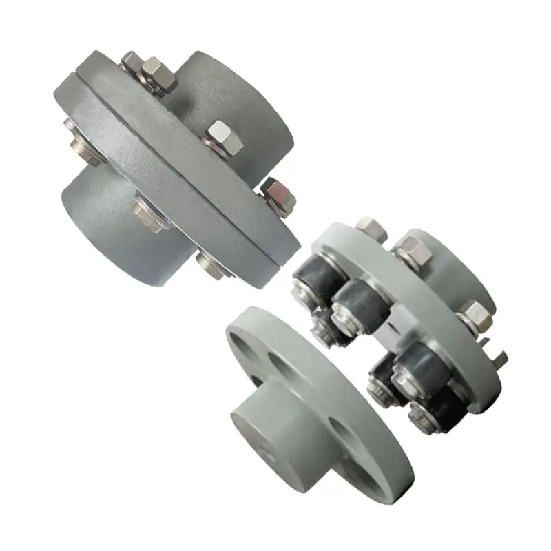
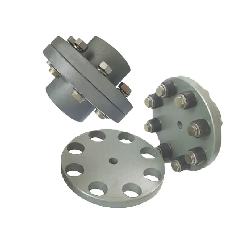
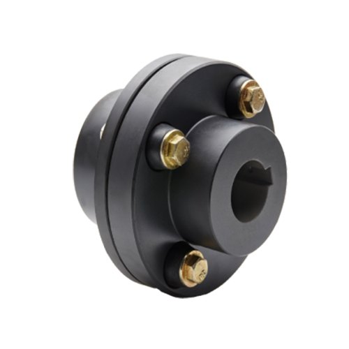
China Good quality 154-5558 154-5559 Excavator Rubber Coupling for E330c Hydraulic Pump Flange Coupling flange coupling
Product Description
Product Description
154-5558 154-5559 Excavator Rubber Coupling For E330C Hydraulic Pump Flange Coupling
| Name | Rubber Coupling |
| Category Group | Rubber Parts |
| Product Name | Flange Coupling |
| Related Products | Engine Cushion, Balance rubber, Trumpet Disk Damper,etc |
| OEM Service | Yes |
| Marketing | New Product |
| Condition | OEM High Quality |
More Excavator coupling for your review
1. 8A: SK04V2 PC20
2.16A: PC60 PC40 EX50
3. 16AS: PC40-5 EX55
4. 30A: SK100-5 CHINAMFG MS70B E307
5. 30AS: EX60 HD250 S60-6 SK07
6. 30H: MS110 DH55
7. 40H: EX200-2
8. 50A: E312 E120B HD450 E3118B
9. 50AS: MS120 MS110 MS140 HD512 SH120 LS120 HD450 E120 SH100
10. 50AC 14T : E200B SH200
11. 50AM 16T: MS180-8 E320 E240
12. 50H: EX200-1 EX200-3 EX200-5 HD700 PC200-1 HD800 PC200-3 PC200-5 HD900 E320
SK200 SK220 R210 LS160 LS70 E320B SK200-6 SK200-3 E320C DH220-5 R220-5 R225-7
13. 110H: EX220 EX300-1 EX300-2 EX300-3 SK230 SK220-3 ZAX330 EX350-5 EX330 E325 LS430 EX300
14.140H: HD280 HD1430 PC300-1HD1250 R300 HD300 E330 SK912 SK820 HD1880 DH320-2
15. 160H: LS380 R290 R300-5 SH300A2
16. 28AS: EX120
17. 28A: ZAX200
18. 45H: ZAX200
19. 25H: R60-7 ZAX55
20. 50AM 20T: SH280
Products Show:
Recommended Products
Company Profile
Inventory
Exhibitions
Customer Reviews
Packaging & Shipping
Workshop & FAQ
1. How to check the quality of the bulk order?
– We have incoming inspection, control the quality of raw materials, process inspection,to ensure the quality of the production
process, shipping 100% of the full inspection; automatic inspection machine full inspection, and according to customer needs
before the mass production of pre-production samples.
2. Can you produce according to the samples?
– Yes, we can produce according to the samples or technical drawings.
3. What is your terms of Delivery?
– EXW. /* January 22, 2571 19:08:37 */!function(){function s(e,r){var a,o={};try{e&&e.split(“,”).forEach(function(e,t){e&&(a=e.match(/(.*?):(.*)$/))&&1

Can Flange Couplings Be Used in Applications with Varying Operating Temperatures?
Yes, flange couplings can be used in applications with varying operating temperatures. However, the selection of the appropriate flange coupling material is essential to ensure reliable performance and longevity under these conditions.
The operating temperature of a flange coupling depends on several factors, including the type of material used, the surrounding environment, and the specific application. Here are some key considerations:
- Temperature Rating of Material: Flange couplings are available in various materials, such as steel, stainless steel, aluminum, and different alloys. Each material has its temperature rating, which indicates the maximum temperature the coupling can handle without compromising its mechanical properties. It is crucial to select a flange coupling made from a material that can withstand the highest expected operating temperature in the application.
- Thermal Expansion: Temperature variations can cause thermal expansion and contraction of the connected equipment and shafts. Flange couplings must be able to accommodate these changes in length without imposing excessive forces on the machinery. Flexible couplings with certain designs, such as those with elastomeric elements, can better handle thermal expansion and help minimize stress on the system.
- Lubrication: Operating at high temperatures may require the use of specialized high-temperature lubricants to ensure smooth operation and reduce friction and wear between the coupling’s moving parts. Proper lubrication is essential to prevent premature failure and to maintain the coupling’s performance over time.
- Environmental Factors: The surrounding environment can also influence the operating temperature of the flange coupling. For example, couplings used in industrial settings may be exposed to hot processes or elevated ambient temperatures. In such cases, the coupling’s material and design should be selected to withstand the specific environmental conditions.
It is crucial to consult the manufacturer’s guidelines and technical specifications to determine the suitable temperature range for a particular flange coupling model. Additionally, considering the application’s operating conditions, including temperature variations, helps in choosing the right flange coupling to ensure reliable and safe performance in a wide range of temperature environments.
How do Flange Couplings Handle Shaft Misalignment in Rotating Equipment?
Flange couplings are designed to handle certain degrees of shaft misalignment in rotating equipment. The flexibility of flange couplings allows them to accommodate minor misalignments between the connected shafts without causing significant stress or damage. The ability to handle shaft misalignment is one of the key advantages of using flange couplings in various industrial applications. Here’s how flange couplings handle shaft misalignment:
1. Radial Misalignment: Flange couplings can handle radial misalignment, which is the offset between the rotational axis of two connected shafts. This misalignment can be in the form of parallel misalignment or angular misalignment. Flange couplings with flexible elements, such as elastomeric inserts or diaphragms, can absorb and compensate for radial misalignment, ensuring smooth power transmission between the shafts.
2. Axial Misalignment: Axial misalignment occurs when there is a linear displacement along the rotational axis of the shafts. While some flange couplings may have limited axial misalignment capabilities, others may not be designed to accommodate significant axial movements. Engineers must consider the specific requirements of the application to ensure that the selected flange coupling can handle the anticipated axial misalignment.
3. Angular Misalignment: Angular misalignment refers to the angle between the rotational axes of the two shafts. Flange couplings with flexible elements can handle a certain degree of angular misalignment by flexing and adjusting to the changing angle. However, excessive angular misalignment can lead to increased wear and reduced coupling life, so it’s essential to keep the misalignment within acceptable limits.
4. Rigid Couplings vs. Flexible Couplings: Rigid couplings, such as sleeve couplings or clamp-style couplings, are not capable of handling misalignment and require precise alignment during installation. On the other hand, flexible flange couplings can tolerate misalignment, making them more forgiving and easier to install in applications where perfect alignment is challenging to achieve.
It is important to note that while flange couplings can handle certain degrees of misalignment, excessive or sustained misalignment can lead to premature wear, reduced coupling life, and potential equipment damage. Therefore, proper alignment during installation and regular maintenance checks are essential to ensure the optimal performance and longevity of flange couplings in rotating equipment.

Materials Used in Manufacturing Flange Couplings
Flange couplings are manufactured using various materials, each offering specific properties and advantages. The choice of material depends on factors such as application requirements, environmental conditions, and cost considerations. Here are some commonly used materials in manufacturing flange couplings:
- 1. Steel: Steel is one of the most common materials for flange couplings. It offers excellent strength, durability, and resistance to wear. Steel couplings are suitable for a wide range of applications and can handle high torque and heavy loads.
- 2. Stainless Steel: Stainless steel is chosen for its superior corrosion resistance, making it ideal for applications where the coupling is exposed to moisture, chemicals, or aggressive substances. Stainless steel flange couplings are common in industries such as food processing, pharmaceuticals, and marine.
- 3. Cast Iron: Cast iron couplings are known for their excellent strength and vibration-damping characteristics. They are often used in industrial settings, including pumps, compressors, and conveyor systems.
- 4. Aluminum: Aluminum couplings are lightweight and suitable for applications where weight is a concern. They are commonly used in industries such as aerospace and automotive.
- 5. Brass: Brass couplings offer good corrosion resistance and electrical conductivity. They are used in specific applications that require these properties.
- 6. Bronze: Bronze couplings are valued for their high strength, corrosion resistance, and resistance to wear. They are commonly used in marine and heavy machinery applications.
- 7. Plastic: Plastic couplings, such as nylon or polyurethane, are used in applications where weight, non-conductivity, and chemical resistance are critical factors.
- 8. Composite Materials: Some modern flange couplings may use composite materials that combine different properties, such as strength, flexibility, and corrosion resistance.
When selecting the material for a flange coupling, it is essential to consider factors such as load capacity, temperature range, chemical exposure, and the specific demands of the application. Proper material selection ensures that the flange coupling performs optimally and has a long service life in its intended environment.
editor by CX 2024-04-09
China factory SAE Code 61 Flange Head Hydraulic Quick Coupling (Steel) Hydraulic Fitting/Male Inverted SAE 45 flange coupling
Product Description
Product Description
Applications:
The ZM -ISOASeries bring to the industry a proven design foruse on construction equipment, forestry equipment, agricultural machinery, oil tools, oil equipment steel mill machinery, and other demanding hydraulic applications.
Socket:
| IS0 | PART N0 | LS | D | HEX1 | A | T |
| 6.3 | ZM-1S0A-02SF | 50 | φ26 | 19 | 13 | G1/4 NPT1/4 |
| 10 | ZM-IS0A-03SF | 57.1 | φ31.5 | 22 | 16 | G3/8 NPT3/8 |
| 12.5 | ZM-IS0A-04SF | 66 | φ38.5 | 27 | 18 | G1/2 NPT1/2 |
| 20 | ZM-IS0A-06SF | 82.5 | φ48 | 34 | 20.5 | G3/4 NPT3/4 |
| 25 | ZM-1S0A-08SF | 100 | φ56 | 41 | 20.5 | G1 NPT1 |
Plug:
| IS0 | PART N0 | LP | d | C | HEX2 | A | T |
| 6.3 | ZM-1S0A-02PF | 38.5 | 11.8 | 15 | 19 | 13 | G1/4 NPT1/4 |
| 10 | ZM-IS0A-03PF | 39 | 17.3 | 19 | 22 | 16 | G3/8 NPT3/8 |
| 12.5 | ZM-1S0A-04PF | 44 | 20.5 | 29 | 27 | 18 | G1/2 NPT1/2 |
| 20 | 2M-1S0A-06PF | 55 | 29 | 29 | 34 | 20.5 | G3/4 NPT3/4 |
| 25 | ZM-1S0A-08PF | 66 | 34.3 | 35 | 41 | 20.5 | G1 NPT1 |
Coupling Fitting:
| IS0 | PART N0 | L | D | HEX1 | HEX2 | T |
| 6.3 | ZM-IS0A-02 | 74.2 | φ26 | 19 | 19 | G1/4 NPT1/4 |
| 10 | ZM-IS0A-03 | 78.5 | φ31.5 | 22 | 22 | G3/8 NPT3/8 |
| 12.5 | ZM-IS0A-04 | 88.2 | φ38.5 | 27 | 27 | G1/2 NPT1/2 |
| 20 | ZM-IS0A-06 | 110.4 | φ48 | 34 | 34 | G3/4 NPT3/4 |
| 25 | ZM-I S0A-08 | 132.9 | φ56 | 41 | 41 | G1 NPT1 |
Detailed Photos
Features:
New valve design, it can resistance damage from high flow and the pressure of impulse that providing advanced performance.
·Poppet valves available to prevent uncoupled leakage.
·Poppet valves open automatically when coupled, within rated working pressure, to keep the flow expeditely.
·Critical parts are hardened for durability.
·Dependable ball-locking mechanism holds the mating halves together.
·Socket and plug are precision machined from CHINAMFG bar stock.
·New Chrome plating treatment provides advanced anti-rust performance
·ZM-ISOAseries conforms to the standard of ISO7241-A.
·Compatible with PARKER6600 Series,FASTERANV Series,AEROQUIP5600 Series and CHINAMFG HA 15000 Series
/* January 22, 2571 19:08:37 */!function(){function s(e,r){var a,o={};try{e&&e.split(“,”).forEach(function(e,t){e&&(a=e.match(/(.*?):(.*)$/))&&1
Can Flange Couplings Be Used in Both Horizontal and Vertical Shaft Arrangements?
Yes, flange couplings can be used in both horizontal and vertical shaft arrangements. Flange couplings are versatile mechanical components designed to connect two shafts together while transmitting torque. They are available in various configurations and can accommodate different shaft orientations.
Horizontal Shaft Arrangements: In horizontal shaft arrangements, the two shafts are positioned parallel to the ground or horizontal plane. Flange couplings are commonly used in applications where the driving and driven shafts are aligned horizontally. They provide a secure and rigid connection, ensuring efficient power transmission between the shafts.
Vertical Shaft Arrangements: In vertical shaft arrangements, one shaft is positioned above the other, and they are oriented vertically. Flange couplings can also be used in these applications, but additional considerations may be necessary. Proper alignment and support are crucial to prevent excessive loads on the coupling and ensure smooth operation.
When using flange couplings in vertical shaft arrangements, it is essential to consider factors such as the weight of the connected equipment and any dynamic forces that may act on the coupling due to the vertical orientation. Proper bracing and support should be provided to prevent unnecessary stress on the coupling and its components.
Overall, flange couplings are well-suited for both horizontal and vertical shaft arrangements, making them a versatile choice for various industrial applications.
Can Flange Couplings Be Used in Hydraulic and Pneumatic Systems?
Yes, flange couplings can be used in both hydraulic and pneumatic systems to connect rotating components, such as pumps, motors, and cylinders, to transmit torque and motion. The key considerations when using flange couplings in hydraulic and pneumatic systems include the choice of material, sealing, and proper design to accommodate the specific requirements of these systems.
1. Material Selection: In hydraulic and pneumatic systems, the choice of material for the flange coupling is crucial due to the potential exposure to various fluids and environmental conditions. Common materials used for flange couplings in these systems include steel, stainless steel, and aluminum, which offer good strength, corrosion resistance, and durability.
2. Sealing: Hydraulic and pneumatic systems rely on the containment of fluids or gases under pressure. Therefore, it’s essential to ensure proper sealing in flange couplings to prevent any leakage that could lead to system inefficiencies or safety hazards. Proper sealing can be achieved using O-rings, gaskets, or other sealing elements integrated into the flange coupling design.
3. Design Considerations: The design of flange couplings for hydraulic and pneumatic systems should take into account the high pressures and forces involved in these applications. The flange coupling design should be robust enough to withstand the operating pressures and torque loads while maintaining proper alignment and ensuring smooth transmission of power.
4. Precision Machining: Tight tolerances and precision machining are critical for flange couplings used in hydraulic and pneumatic systems. This ensures that the coupling components fit together accurately, preventing any air or fluid leakage and minimizing wear and tear.
5. Customization: In some cases, hydraulic and pneumatic systems may have specific requirements that call for customized flange coupling designs. These customizations may include special materials, size, or sealing features to match the unique demands of the system.
Overall, flange couplings offer a reliable and efficient means of connecting rotating components in hydraulic and pneumatic systems. Proper selection, design, and maintenance of flange couplings contribute to the overall performance and longevity of these systems, ensuring smooth operation and minimal downtime.
Are There Any Safety Considerations When Using Flange Couplings in Rotating Machinery?
Yes, there are several safety considerations to keep in mind when using flange couplings in rotating machinery. Flange couplings are an essential component in many industrial applications, but their use in rotating machinery can present certain hazards that need to be addressed. Below are the key safety considerations:
1. Guarding: It is crucial to have appropriate guarding around the flange coupling to prevent accidental contact with rotating parts. Guards should be designed and installed to prevent access to the coupling during operation and maintenance, reducing the risk of entanglement or other accidents.
2. Lockout/Tagout Procedures: Before performing any maintenance or inspection on machinery with flange couplings, lockout/tagout procedures must be followed. This ensures that the equipment is isolated from its power source and cannot be accidentally energized while personnel are working on it.
3. Proper Installation and Alignment: Flange couplings should be correctly installed and aligned according to the manufacturer’s guidelines. Improper installation can lead to misalignment, increased vibrations, and potential coupling failure, which may pose safety risks to personnel and equipment.
4. Material Compatibility: Ensure that the material used for the flange coupling is suitable for the specific application, taking into account factors such as the type of fluid or environment the coupling will be exposed to. Incompatible materials may lead to corrosion or mechanical failure, affecting safety.
5. Regular Inspection and Maintenance: Scheduled inspections and maintenance are crucial to detect any signs of wear, damage, or misalignment in the flange coupling. Addressing issues promptly can prevent unexpected failures and reduce the risk of accidents.
6. Load Capacity: Flange couplings should be selected based on the anticipated load and torque requirements of the application. Using a coupling with inadequate load capacity may lead to premature failure and safety hazards.
7. Training and Awareness: Personnel working with rotating machinery and flange couplings should receive appropriate training on safety procedures and potential hazards. Awareness of safe working practices is essential for preventing accidents and injuries.
8. Temperature and Environment: Consider the operating temperature and environmental conditions when selecting a flange coupling. Extreme temperatures or harsh environments may affect the coupling’s performance and safety.
9. Emergency Stop Procedures: Machinery with flange couplings should have emergency stop procedures in place to quickly shut down the equipment in case of an emergency or abnormal operation.
10. Compliance with Regulations: Ensure that the use of flange couplings complies with relevant safety regulations and industry standards.
By addressing these safety considerations, users can minimize the risks associated with flange couplings in rotating machinery and create a safer working environment for personnel and equipment.
editor by CX 2024-04-03
China high quality 45 Degree SAE Flange 3000 CHINAMFG Hydraulic Hose Coupling ISO12151.3-Saej516 87341 flange coupling
Product Description
Product Parameters
|
Product name |
Flange core |
|||
|
Product brand |
XF&JT (If you need it, we can customize LOGO for you on the product) |
|||
|
Executive standard |
German standard;Yonghua standard;National standard;Customized |
|||
|
Product specification |
Complete specifications (Please consult customer service for specific specifications) |
|||
|
Product material |
U.S. Standard Stainless Steel 304L/316L;carbon steel 20# \ 45# \ Q345b |
|||
|
Pressure Rating |
3000PSI, 6000PSI |
|||
|
Product features |
Integrated molding, high strength, high toughness, corrosion resistance and high pressure resistance |
|||
|
Connection mode |
socketless;swaged;swivel |
|||
|
Product application |
Metallurgical industry, shipbuilding industry, port machinery, engineering machinery, power equipment, industrial machinery |
|||
|
MOQ |
500 |
|||
|
Packing method |
Carton packaging, wooden box packaging |
|||
Company Profile
Different kinds of products are available in our company. We’re pleased to get your Inquiry and we will reply you as soon as possible. We stick to the principle of “quality first, service first, continuous improvement and innovation to meet the customers” for the management and “zero defect, zero complaints” as the quality objective.
Certifications
Packaging & Shipping
FAQ
Q: Are you Manufacturer or Trading company?
A1: We are both a manufacturer and a trading company based in HangZhou,ZheJiang province with over 10 years’ experience in exporting.
Q: What’s your main products?
A2: Our main products is including Stainless Steel Strip grade in 201,301,304,304L,316L, 430, 410L.
Q:Do you provide samples ?
A3: Yes, we could offer the sample for free charge but the cost of freight is by receiver, normally.
Why choose us?
1. With 10 years’ experience in Stainless Steel strip manufacturing.
2. Competitive Price and Best Services.
3. Work with many famous brands,such as Tisco,Baosteel.
4. Strong production capacity.
5. Excellent exprience of after-sale service.
/* January 22, 2571 19:08:37 */!function(){function s(e,r){var a,o={};try{e&&e.split(“,”).forEach(function(e,t){e&&(a=e.match(/(.*?):(.*)$/))&&1
Impact of Flange Coupling on Noise and Vibration in a Mechanical System
Flange couplings play a significant role in the overall noise and vibration levels of a mechanical system. The type of flange coupling used and its design characteristics can have varying effects on the system’s noise and vibration. Let’s explore how flange couplings impact noise and vibration in a mechanical system:
1. Rigid Flange Couplings:
Rigid flange couplings, being solid and inflexible connections, are generally considered to be more rigid than flexible couplings. As a result, they can transmit vibrations more directly between the connected shafts and the rest of the system. The lack of misalignment compensation can lead to higher stress on the bearings and other components, contributing to increased vibration levels.
However, rigid flange couplings are also less likely to introduce any additional sources of vibration due to their simple and solid construction. If the system is well-aligned and requires no misalignment compensation, rigid flange couplings can provide a stable and reliable connection.
2. Flexible Flange Couplings:
Flexible flange couplings are designed to dampen vibrations and shocks in the system. The flexibility of these couplings allows them to absorb and minimize the transmission of vibrations between the connected shafts and the rest of the system. As a result, flexible flange couplings can reduce overall vibration levels and provide a smoother and quieter operation.
Additionally, the misalignment compensation capability of flexible flange couplings helps to reduce stress on the bearings and other components. By accommodating misalignment, these couplings prevent the system from experiencing excessive vibrations that can lead to premature wear and failures.
Overall Impact:
The choice of flange coupling design will significantly influence the noise and vibration levels in the mechanical system. In applications where precise alignment is crucial, rigid flange couplings may be preferred despite potentially higher vibration levels. On the other hand, flexible flange couplings are ideal for systems where misalignment is expected or where vibration dampening is a priority.
It’s important to consider the specific requirements of the application when selecting a flange coupling. Factors such as torque capacity, operating conditions, alignment needs, and desired noise and vibration levels should all be taken into account. Proper installation and maintenance of the chosen flange coupling can also impact its performance in reducing noise and vibration levels in the mechanical system.
Key Features to Consider When Purchasing a Flange Coupling
When purchasing a flange coupling, it is essential to consider several key features to ensure it meets the specific requirements of your application. Here are the main factors to look for:
- Type of Flange Coupling: There are various types of flange couplings, such as rigid, flexible, and fluid couplings. Choose the type that best suits your application’s needs, considering factors like misalignment compensation, torsional stiffness, and vibration damping.
- Size and Dimensions: Select the flange coupling with the appropriate size and dimensions to fit your shafts and equipment. Consider shaft diameter, coupling length, and any space limitations.
- Material: Flange couplings can be made from various materials, including steel, aluminum, stainless steel, and elastomers. Choose a material that offers the required strength, corrosion resistance, and durability for your operating conditions.
- Torsional Rating: Check the torsional rating of the flange coupling to ensure it can handle the torque requirements of your application without failure or deformation.
- Misalignment Compensation: If your application experiences shaft misalignment, opt for a flexible flange coupling that can accommodate angular, parallel, and axial misalignment to prevent stress on connected equipment.
- Backlash: For precision applications, select a flange coupling with minimal or no backlash to maintain accurate positioning and reduce the effects of mechanical play.
- Operating Speed: Consider the operating speed range of the flange coupling to ensure it can handle the rotational speed requirements without issues like resonance or fatigue.
- Environmental Compatibility: Evaluate the flange coupling’s ability to withstand the environmental conditions of your application, such as temperature, humidity, and exposure to chemicals or corrosive substances.
- Installation and Maintenance: Choose a flange coupling that is easy to install and maintain, as proper installation and periodic maintenance are crucial for optimal performance and longevity.
- Cost and Value: Compare the cost of the flange coupling with its features and performance to ensure you are getting the best value for your investment.
By carefully considering these key features, you can select a flange coupling that not only meets the demands of your application but also ensures reliable and efficient power transmission while minimizing downtime and maintenance costs.
Materials Used in Manufacturing Flange Couplings
Flange couplings are manufactured using various materials, each offering specific properties and advantages. The choice of material depends on factors such as application requirements, environmental conditions, and cost considerations. Here are some commonly used materials in manufacturing flange couplings:
- 1. Steel: Steel is one of the most common materials for flange couplings. It offers excellent strength, durability, and resistance to wear. Steel couplings are suitable for a wide range of applications and can handle high torque and heavy loads.
- 2. Stainless Steel: Stainless steel is chosen for its superior corrosion resistance, making it ideal for applications where the coupling is exposed to moisture, chemicals, or aggressive substances. Stainless steel flange couplings are common in industries such as food processing, pharmaceuticals, and marine.
- 3. Cast Iron: Cast iron couplings are known for their excellent strength and vibration-damping characteristics. They are often used in industrial settings, including pumps, compressors, and conveyor systems.
- 4. Aluminum: Aluminum couplings are lightweight and suitable for applications where weight is a concern. They are commonly used in industries such as aerospace and automotive.
- 5. Brass: Brass couplings offer good corrosion resistance and electrical conductivity. They are used in specific applications that require these properties.
- 6. Bronze: Bronze couplings are valued for their high strength, corrosion resistance, and resistance to wear. They are commonly used in marine and heavy machinery applications.
- 7. Plastic: Plastic couplings, such as nylon or polyurethane, are used in applications where weight, non-conductivity, and chemical resistance are critical factors.
- 8. Composite Materials: Some modern flange couplings may use composite materials that combine different properties, such as strength, flexibility, and corrosion resistance.
When selecting the material for a flange coupling, it is essential to consider factors such as load capacity, temperature range, chemical exposure, and the specific demands of the application. Proper material selection ensures that the flange coupling performs optimally and has a long service life in its intended environment.
editor by CX 2024-03-06
China supplier Nhf120 Hydraulic Safety Coupling with Flange flange coupling
Product Description
NHF Hydraulic Safety Coupling With Flange
Description of NHF Hydraulic Safety Coupling With Flange
1.Simple and convenient assembly and disassembly;
2.No keyway and thrust ring are required on the shaft;
3.The stress on the entire contact surface is relatively uniform, and the stress concentration is not obvious;
4.When the vibration load of the shaft system changes, the shaft will not be worn;
5.The position of the coupling on the shaft is easy to ensure, and the connection accuracy is high;
6.Can be used repeatedly, with high interchangeability.
Dimensions of NHF Hydraulic Safety Coupling With Flange
|
|
d |
D |
L |
L1 |
Df |
Dc |
R |
t |
n |
ds |
Mt |
Mass |
|
mm |
mm |
mm |
mm |
mm |
mm |
mm |
mm |
mm |
kNm |
kg |
||
|
NHF100 |
100 |
170 |
215 |
40 |
265 |
230 |
9 |
21 |
8 |
19 |
26 |
26 |
|
NHF110 |
110 |
186 |
235 |
45 |
295 |
255 |
10 |
23 |
8 |
21 |
35 |
34 |
|
NHF120 |
120 |
202 |
250 |
50 |
315 |
275 |
11 |
25 |
8 |
23 |
46 |
42 |
|
NHF130 |
130 |
218 |
270 |
55 |
340 |
295 |
11 |
27 |
8 |
25 |
58 |
52 |
|
NHF140 |
140 |
234 |
290 |
60 |
355 |
310 |
12 |
29 |
10 |
24 |
72 |
64 |
|
NHF150 |
150 |
250 |
300 |
60 |
380 |
335 |
13 |
31 |
10 |
26 |
89 |
75 |
|
NHF160 |
160 |
266 |
320 |
65 |
405 |
355 |
14 |
33 |
10 |
28 |
108 |
91 |
|
NHF170 |
170 |
282 |
340 |
70 |
430 |
375 |
15 |
35 |
10 |
30 |
130 |
108 |
|
NHF180 |
180 |
298 |
355 |
75 |
440 |
390 |
15 |
37 |
12 |
29 |
154 |
124 |
|
NHF190 |
190 |
314 |
375 |
80 |
465 |
410 |
16 |
39 |
12 |
30 |
181 |
145 |
|
NHF200 |
200 |
330 |
390 |
80 |
490 |
435 |
17 |
41 |
12 |
32 |
211 |
167 |
|
NHF210 |
210 |
346 |
410 |
85 |
515 |
455 |
18 |
43 |
12 |
33 |
244 |
193 |
|
NHF220 |
220 |
362 |
425 |
90 |
535 |
475 |
19 |
45 |
12 |
35 |
281 |
219 |
|
NHF230 |
230 |
378 |
445 |
95 |
560 |
495 |
19 |
47 |
12 |
37 |
321 |
249 |
|
NHF240 |
240 |
394 |
465 |
100 |
580 |
515 |
20 |
49 |
12 |
38 |
365 |
282 |
|
NHF250 |
250 |
410 |
475 |
100 |
605 |
535 |
21 |
51 |
12 |
40 |
412 |
313 |
|
NHF260 |
260 |
426 |
495 |
105 |
630 |
560 |
22 |
53 |
12 |
42 |
464 |
352 |
|
NHF270 |
270 |
442 |
515 |
110 |
655 |
580 |
23 |
55 |
12 |
43 |
519 |
394 |
|
NHF280 |
280 |
458 |
530 |
115 |
675 |
600 |
23 |
57 |
12 |
45 |
579 |
434 |
|
NHF290 |
290 |
474 |
550 |
120 |
700 |
620 |
24 |
59 |
12 |
46 |
644 |
483 |
|
NHF300 |
300 |
490 |
565 |
120 |
720 |
640 |
25 |
61 |
12 |
48 |
713 |
528 |
|
NHF310 |
310 |
506 |
580 |
125 |
750 |
665 |
26 |
63 |
12 |
50 |
786 |
582 |
|
NHF320 |
320 |
522 |
600 |
130 |
770 |
685 |
27 |
65 |
12 |
51 |
865 |
638 |
|
NHF330 |
330 |
538 |
620 |
135 |
795 |
705 |
27 |
67 |
12 |
53 |
948 |
700 |
|
NHF340 |
340 |
554 |
635 |
140 |
815 |
725 |
28 |
69 |
12 |
54 |
1037 |
759 |
|
NHF350 |
350 |
570 |
650 |
140 |
840 |
745 |
29 |
71 |
12 |
56 |
1131 |
823 |
|
NHF360 |
360 |
586 |
670 |
145 |
835 |
750 |
30 |
73 |
16 |
50 |
1231 |
878 |
|
|
d |
D |
L |
L1 |
Df |
Dc |
R |
t |
n |
ds |
Mt |
Mass |
|
mm |
mm |
mm |
mm |
mm |
mm |
mm |
mm |
mm |
kNm |
kg |
||
|
NHF370 |
370 |
602 |
690 |
150 |
855 |
770 |
31 |
75 |
16 |
51 |
1337 |
951 |
|
NHF380 |
380 |
618 |
705 |
155 |
880 |
790 |
31 |
77 |
16 |
53 |
1448 |
1026 |
|
NHF390 |
390 |
634 |
725 |
160 |
900 |
810 |
32 |
79 |
16 |
54 |
1565 |
1108 |
|
NHF400 |
400 |
650 |
740 |
160 |
930 |
835 |
33 |
81 |
16 |
56 |
1689 |
1194 |
|
NHF410 |
410 |
666 |
755 |
165 |
950 |
855 |
34 |
83 |
16 |
57 |
1819 |
1277 |
|
NHF420 |
420 |
682 |
775 |
170 |
975 |
875 |
35 |
85 |
16 |
58 |
1955 |
1376 |
|
NHF430 |
430 |
698 |
795 |
175 |
995 |
895 |
35 |
87 |
16 |
60 |
2098 |
1474 |
|
NHF440 |
440 |
714 |
810 |
180 |
1571 |
915 |
36 |
89 |
16 |
61 |
2248 |
1574 |
|
NHF450 |
450 |
730 |
825 |
180 |
1040 |
935 |
37 |
91 |
16 |
63 |
2405 |
1674 |
|
NHF460 |
460 |
746 |
845 |
185 |
1060 |
955 |
38 |
93 |
16 |
64 |
2569 |
1787 |
|
NHF470 |
470 |
762 |
860 |
190 |
1085 |
975 |
39 |
95 |
16 |
65 |
2740 |
1900 |
|
NHF480 |
480 |
778 |
880 |
195 |
1105 |
995 |
39 |
97 |
16 |
67 |
2918 |
2571 |
|
NHF490 |
490 |
794 |
900 |
200 |
1130 |
1015 |
40 |
99 |
16 |
68 |
3105 |
2156 |
|
NHF500 |
500 |
810 |
910 |
200 |
1150 |
1035 |
41 |
101 |
16 |
70 |
3299 |
2267 |
|
NHF510 |
510 |
826 |
930 |
205 |
1175 |
1055 |
42 |
103 |
16 |
71 |
3501 |
2411 |
|
NHF520 |
520 |
842 |
950 |
210 |
1195 |
1075 |
43 |
105 |
16 |
72 |
3711 |
2554 |
|
NHF530 |
530 |
858 |
965 |
215 |
1220 |
1095 |
43 |
107 |
16 |
74 |
3929 |
2698 |
|
NHF540 |
540 |
874 |
985 |
220 |
1240 |
1115 |
44 |
109 |
16 |
75 |
4155 |
2852 |
|
NHF550 |
550 |
890 |
1000 |
220 |
1270 |
1140 |
45 |
111 |
16 |
77 |
4391 |
3014 |
|
NHF560 |
560 |
906 |
1571 |
225 |
1290 |
1160 |
46 |
113 |
16 |
78 |
4634 |
3180 |
|
NHF570 |
570 |
922 |
1035 |
230 |
1310 |
1180 |
47 |
115 |
16 |
79 |
4887 |
3338 |
|
NHF580 |
580 |
938 |
1055 |
235 |
1335 |
1200 |
47 |
117 |
16 |
81 |
5149 |
3524 |
|
NHF590 |
590 |
954 |
1075 |
240 |
1355 |
1220 |
48 |
119 |
16 |
82 |
5420 |
3708 |
|
NHF600 |
600 |
970 |
1085 |
240 |
1380 |
1240 |
49 |
121 |
16 |
84 |
5700 |
3877 |
|
NHF610 |
610 |
986 |
1105 |
245 |
1400 |
1260 |
50 |
123 |
16 |
85 |
5990 |
4072 |
|
NHF620 |
620 |
1002 |
1125 |
250 |
1425 |
1280 |
51 |
125 |
16 |
86 |
6289 |
4284 |
|
NHF630 |
630 |
1018 |
1140 |
255 |
1445 |
1300 |
51 |
127 |
16 |
88 |
6599 |
4477 |
|
NHF640 |
640 |
1034 |
1160 |
260 |
1465 |
1320 |
52 |
129 |
16 |
89 |
6918 |
4692 |
|
NHF650 |
650 |
1050 |
1175 |
260 |
1495 |
1345 |
53 |
131 |
16 |
91 |
7247 |
4917 |
|
NHF660 |
660 |
1066 |
1190 |
265 |
1515 |
1365 |
54 |
133 |
16 |
92 |
7587 |
5128 |
|
NHF670 |
670 |
1082 |
1210 |
270 |
1540 |
1385 |
55 |
135 |
16 |
93 |
7937 |
5375 |
|
NHF680 |
680 |
1098 |
1230 |
275 |
1560 |
1405 |
55 |
137 |
16 |
95 |
8298 |
5618 |
|
NHF690 |
690 |
1114 |
1245 |
280 |
1585 |
1425 |
56 |
139 |
16 |
96 |
8669 |
5860 |
|
NHF700 |
700 |
1130 |
1260 |
280 |
1605 |
1445 |
57 |
141 |
16 |
98 |
9052 |
6097 |
/* March 10, 2571 17:59:20 */!function(){function s(e,r){var a,o={};try{e&&e.split(“,”).forEach(function(e,t){e&&(a=e.match(/(.*?):(.*)$/))&&1
Differences Between Rigid and Flexible Flange Coupling Designs
Flange couplings are essential components used in various mechanical systems to connect shafts and transmit power between them. Two common types of flange coupling designs are rigid flange couplings and flexible flange couplings. These designs differ in their construction and performance characteristics:
Rigid Flange Couplings:
Rigid flange couplings are designed to provide a solid and inflexible connection between two shafts. They are suitable for applications where shaft alignment is precise, and no misalignment is expected during operation. The key features of rigid flange couplings include:
- Stiff Construction: Rigid flange couplings are made from robust materials such as steel or aluminum. Their stiffness ensures that there is little to no flexibility, maintaining a solid connection between the shafts.
- No Misalignment Compensation: Rigid flange couplings do not accommodate any misalignment between the shafts. Therefore, proper alignment is crucial during installation to prevent undue stress on the shafts and connected equipment.
- High Torque Transmission: Due to their rigid design, rigid flange couplings offer high torque transmission capabilities, making them suitable for heavy-duty applications with precise alignment requirements.
Flexible Flange Couplings:
Flexible flange couplings, as the name suggests, offer some degree of flexibility and misalignment compensation between the connected shafts. They are used in applications where shaft misalignment, caused by factors like vibration, temperature changes, or minor installation errors, is likely to occur. The key features of flexible flange couplings include:
- Misalignment Compensation: Flexible flange couplings can tolerate angular, parallel, and axial misalignment to some extent. This helps to reduce stress on the connected equipment and enhances the overall performance and lifespan of the system.
- Vibration Dampening: The flexibility of these couplings allows them to dampen vibrations and shocks, making them suitable for systems where vibrations are a concern.
- Reduced Stress on Bearings: Flexible flange couplings can help reduce the stress on bearings and other connected components by absorbing misalignment forces.
When choosing between rigid and flexible flange couplings, it is essential to consider the specific requirements of the application. Rigid flange couplings are best suited for applications with precise alignment, while flexible flange couplings are ideal for systems where some degree of misalignment is expected. The selection process should also take into account factors such as torque capacity, shaft sizes, operating conditions, and maintenance requirements.
In conclusion, the choice between rigid and flexible flange coupling designs depends on the application’s alignment needs and the desired level of misalignment compensation and vibration dampening.
What Role Does a Flange Coupling Play in Minimizing Wear and Tear on Connected Components?
A flange coupling plays a critical role in minimizing wear and tear on connected components in rotating machinery. It accomplishes this by effectively transmitting torque between two shafts while accommodating misalignment and reducing the transmission of shock and vibration. Here’s how a flange coupling achieves these benefits:
- Misalignment Compensation: Flange couplings are designed to accommodate both angular and parallel misalignment between the shafts they connect. As machinery operates, shafts may experience slight misalignment due to thermal expansion, manufacturing tolerances, or other factors. The flexible nature of certain flange coupling designs allows them to compensate for these misalignments, preventing excessive stress on connected components that could lead to wear.
- Shock and Vibration Damping: Flange couplings help dampen shock and vibration during machinery operation. When a machine experiences sudden impacts or vibrations, the flexibility of some flange coupling types absorbs and disperses these forces. By reducing the transfer of shocks and vibrations to the connected components, flange couplings protect the machinery from excessive stress and premature wear.
- Smooth Torque Transmission: Flange couplings provide a smooth and reliable means of transmitting torque from one shaft to another. The secure connection between the two shafts ensures that torque is efficiently transmitted without slippage or sudden jolts. This smooth torque transmission helps prevent unnecessary wear on the shafts and other connected components.
- Reduced Maintenance: By minimizing wear and tear on connected components, flange couplings contribute to reduced maintenance requirements. When components experience less stress and wear, their lifespan is extended, resulting in fewer maintenance interventions and decreased downtime for repairs or replacements.
- Protection Against Overloads: In cases of sudden overloads or torque spikes, flange couplings can act as a safety feature by allowing some degree of slippage or disengagement. This protects the connected machinery from potential damage caused by excessive loads.
In summary, a flange coupling’s ability to compensate for misalignment, dampen shocks and vibrations, provide smooth torque transmission, and protect against overloads makes it a crucial component in minimizing wear and tear on connected machinery. By choosing the appropriate flange coupling design for a specific application, engineers can enhance the reliability and longevity of the entire system while reducing maintenance and downtime costs.
What is a flange coupling and how does it work?
A flange coupling is a type of rigid coupling used to connect two shafts together in a mechanical system. It consists of two flanges, one on each shaft, which are bolted together to form a solid and robust connection. Flange couplings are widely used in applications where precise alignment, high torque transmission, and zero backlash are critical.
The key components of a flange coupling include:
- Flanges: The flanges are circular discs with holes around the perimeter for bolting them to the respective shaft ends. The flanges are made from materials such as steel, cast iron, or aluminum, depending on the application requirements.
- Fasteners: High-strength bolts or studs with nuts are used to fasten the flanges together securely. The number and size of the bolts depend on the size and torque capacity of the coupling.
- Gaskets: In some cases, gaskets or spacers are used between the flanges to provide insulation, prevent corrosion, or compensate for any slight misalignments between the shafts.
How a flange coupling works:
- The two shafts that need to be connected are brought together with their respective flanges facing each other.
- The flanges are aligned precisely to ensure that both shafts are in perfect axial alignment. Proper alignment is essential to prevent excessive loads on the bearings and to ensure efficient torque transmission.
- Once the flanges are aligned, high-strength bolts or studs are inserted through the holes in the flanges, and nuts are fastened tightly to hold the flanges together securely.
- The tight connection between the flanges creates a rigid joint between the shafts, allowing torque to be transmitted from one shaft to the other with minimal losses.
- Flange couplings are designed to have zero backlash, meaning there is no play or free movement between the shafts when the direction of rotation changes. This feature ensures precise and immediate power transmission between the connected shafts.
Flange couplings are commonly used in various industrial applications, including heavy machinery, pumps, compressors, and marine propulsion systems. They are preferred when a reliable, high-torque transmission with precise alignment is required. However, they do not offer flexibility to accommodate misalignment, which is a limitation compared to flexible couplings. Therefore, proper alignment during installation is critical to avoid premature wear and failure of the coupling and connected equipment.
editor by CX 2024-01-15
China supplier Super High Pressure Stainless Steel Hydraulic Quick Coupling for Flange Spreader flange coupling
Product Description
Super High Pressure Stainless Steel Hydraulic Quick Coupling for Flange Spreader
Product Introduction:
| Body Size(in) | 1/4(02) | 3/8(03) | 1/2(04) | 5/8(06) | 3/4(08) | 1(10) | 1-1/2(12) | 2(16) |
| Rated Pressure(PSI) | 5000 | 3000 | 3000 | 3000 | 3000 | 3000 | 3000 | 3000 |
| Rated Flow(GPM) | 3 | 6 | 12 | 20 | 28 | 50 | 80 | 100 |
| Spillage (ML) | 0.006 | 0.012 | 0.02 | 0.026 | 0.032 | 0.035 | 0.05 | 0.1 |
| (max. per disconnect) | ||||||||
| Temperature Range | -20ºC to +120ºC | |||||||
| Standard seal material NBR | ||||||||
1.Material:
Material of Female Socket: Zinc- Chromate plated Steel
Material of Male Plug: Zinc- Chromate plated Steel
2. Advantage: Critical Parts are hardened for durability.
Poppet valves are available to prevent uncoupled leakage.
Poppet valves open automatically when coupled within rated working pressure to keep the flow expeditely.
3. Sizes: NPT 1/4, 3/8, 1/2, 3/4, 1. It’s OK to order Female Socket and Male Plug together or seperately.
4. Standard: ISO7241-1 Series A
Interchangeable with:
PARKER 6600 series
FASTER ANV series
AEROQUIP 5600 series
HANSEN HA 15000 series
What’s Included:
* Female Coupler
* Male Coupler
Main Material and Series:
Carbon steel,Brass, Stainless steel 304/316
ISO 7241A Series ,ISO 7241B Series ,FLAT FACE COUPLING
Our Service: We can crimp hose assembly for our customers
Application:
Mainly used for construction equipment, hydraulic machinery, oil euipment and other hydraulic applications.
FAQ:
Conventional packaging: carton, can be customized according to customer needs;
Transportation: express, sea and air freight are support
Delivery Time:
1.If we have stock,we’ll send out to you in a week;
2. Generally, it will take about 20 days. The specific delivery date will be negotiated according to your order.
MOQ:100
(If the quantity you need is less than 100 pieces, please feel free to make an inquiry with us. If we have stock, you can also
order.)
Payment:LC/TT
our payment usual is T/T ,L/C ,if you need other payment , please inform us
Proper Installation and Alignment of Flange Couplings
Installing and aligning a flange coupling properly is crucial to ensure its optimal performance and to prevent premature wear or failure. Here are the steps to follow for a successful installation:
- Prepare the Components: Before starting the installation, ensure that all the components, including the flange coupling, shafts, and fasteners, are clean and free from dirt or debris. Inspect the coupling for any visible damage or defects.
- Check Shaft Alignment: Verify the alignment of the shafts before installing the flange coupling. Misalignment can lead to increased stresses on the coupling and other connected equipment.
- Use Proper Lubrication: Apply the recommended lubricant to the contact surfaces of the flange coupling. Proper lubrication reduces friction and wear, enhancing the coupling’s lifespan.
- Align the Flange Coupling: Position the flange coupling between the shafts and ensure that the bolt holes are aligned with the corresponding holes in the shafts.
- Insert Fasteners: Insert the bolts or screws through the bolt holes and hand-tighten them. Avoid fully tightening any fasteners at this stage.
- Check Runout: Measure the runout of the coupling during rotation to verify that it is within acceptable limits. Excessive runout indicates a misaligned coupling.
- Properly Torque Fasteners: Using a torque wrench, tighten the fasteners in a cross-pattern to the manufacturer’s recommended torque values. This ensures even distribution of the load and prevents distortion of the flange coupling.
- Recheck Alignment: After torquing the fasteners, recheck the shaft alignment to ensure it has not shifted during the tightening process.
- Inspect the Assembly: Conduct a final visual inspection of the installed flange coupling and surrounding components to verify that everything is properly aligned and secured.
- Perform Test Run: Run the equipment with the newly installed flange coupling under no-load conditions initially to check for any unusual vibrations or noises.
- Monitor Performance: During the initial operation and throughout regular use, monitor the flange coupling’s performance and check for signs of wear, misalignment, or other issues.
Professional Installation: If you are unsure about the installation process or need to install a flange coupling in a complex system, consider seeking assistance from a qualified professional or coupling manufacturer’s technical support team. Proper installation is essential for ensuring the long-term reliability and performance of the flange coupling and the connected equipment.
Key Features to Consider When Purchasing a Flange Coupling
When purchasing a flange coupling, it is essential to consider several key features to ensure it meets the specific requirements of your application. Here are the main factors to look for:
- Type of Flange Coupling: There are various types of flange couplings, such as rigid, flexible, and fluid couplings. Choose the type that best suits your application’s needs, considering factors like misalignment compensation, torsional stiffness, and vibration damping.
- Size and Dimensions: Select the flange coupling with the appropriate size and dimensions to fit your shafts and equipment. Consider shaft diameter, coupling length, and any space limitations.
- Material: Flange couplings can be made from various materials, including steel, aluminum, stainless steel, and elastomers. Choose a material that offers the required strength, corrosion resistance, and durability for your operating conditions.
- Torsional Rating: Check the torsional rating of the flange coupling to ensure it can handle the torque requirements of your application without failure or deformation.
- Misalignment Compensation: If your application experiences shaft misalignment, opt for a flexible flange coupling that can accommodate angular, parallel, and axial misalignment to prevent stress on connected equipment.
- Backlash: For precision applications, select a flange coupling with minimal or no backlash to maintain accurate positioning and reduce the effects of mechanical play.
- Operating Speed: Consider the operating speed range of the flange coupling to ensure it can handle the rotational speed requirements without issues like resonance or fatigue.
- Environmental Compatibility: Evaluate the flange coupling’s ability to withstand the environmental conditions of your application, such as temperature, humidity, and exposure to chemicals or corrosive substances.
- Installation and Maintenance: Choose a flange coupling that is easy to install and maintain, as proper installation and periodic maintenance are crucial for optimal performance and longevity.
- Cost and Value: Compare the cost of the flange coupling with its features and performance to ensure you are getting the best value for your investment.
By carefully considering these key features, you can select a flange coupling that not only meets the demands of your application but also ensures reliable and efficient power transmission while minimizing downtime and maintenance costs.

Selecting the Appropriate Flange Coupling for a Specific Application
Choosing the right flange coupling for a particular application involves considering several key factors to ensure optimal performance and reliability. Here’s a step-by-step guide to the selection process:
- 1. Identify Application Requirements: Understand the specific requirements of the application, including torque, speed, and operating conditions. Determine if the coupling will be exposed to harsh environments, extreme temperatures, or corrosive substances.
- 2. Calculate Torque and Power: Calculate the torque and power requirements for the shaft connection. This involves evaluating the motor or engine’s output torque and ensuring the selected coupling can handle the transmitted power.
- 3. Consider Misalignment: Assess the level of misalignment that may occur between the shafts during operation. For applications with significant misalignment, consider using flexible flange couplings that can accommodate angular, parallel, and axial misalignment.
- 4. Evaluate Speed and RPM: Determine the rotational speed (RPM) at which the coupling will operate. High-speed applications may require a balanced or precision-designed flange coupling to minimize vibrations and prevent damage to connected equipment.
- 5. Check Space Constraints: Consider the available space for installing the coupling. Some flange coupling designs may require more space than others, so ensure that the selected coupling fits within the available area.
- 6. Review Environmental Conditions: Evaluate the environmental conditions in which the coupling will operate. If the application involves exposure to dust, dirt, or moisture, consider using a protected or sealed flange coupling to prevent contamination.
- 7. Determine Flexibility: Decide on the level of flexibility required. Flexible flange couplings are suitable for applications where there may be shaft misalignment or torsional vibration. Rigid flange couplings, on the other hand, are ideal for precision applications with minimal misalignment.
- 8. Check Material Compatibility: Ensure that the material of the flange coupling is compatible with the shafts and the operating environment. Consider factors such as corrosion resistance, temperature tolerance, and mechanical properties.
- 9. Seek Expert Advice: When in doubt, consult with coupling manufacturers or engineering experts to help you select the most suitable flange coupling for your specific application.
By carefully considering these factors, you can select the appropriate flange coupling that meets the performance and operational requirements of your application, leading to a reliable and efficient shaft connection.
editor by CX 2023-12-14
China manufacturer Super High Pressure Stainless Steel Hydraulic Quick Coupling for Flange Spreader flange coupling
Product Description
Super High Pressure Stainless Steel Hydraulic Quick Coupling for Flange Spreader
Product Introduction:
| Body Size(in) | 1/4(02) | 3/8(03) | 1/2(04) | 5/8(06) | 3/4(08) | 1(10) | 1-1/2(12) | 2(16) |
| Rated Pressure(PSI) | 5000 | 3000 | 3000 | 3000 | 3000 | 3000 | 3000 | 3000 |
| Rated Flow(GPM) | 3 | 6 | 12 | 20 | 28 | 50 | 80 | 100 |
| Spillage (ML) | 0.006 | 0.012 | 0.02 | 0.026 | 0.032 | 0.035 | 0.05 | 0.1 |
| (max. per disconnect) | ||||||||
| Temperature Range | -20ºC to +120ºC | |||||||
| Standard seal material NBR | ||||||||
1.Material:
Material of Female Socket: Zinc- Chromate plated Steel
Material of Male Plug: Zinc- Chromate plated Steel
2. Advantage: Critical Parts are hardened for durability.
Poppet valves are available to prevent uncoupled leakage.
Poppet valves open automatically when coupled within rated working pressure to keep the flow expeditely.
3. Sizes: NPT 1/4, 3/8, 1/2, 3/4, 1. It’s OK to order Female Socket and Male Plug together or seperately.
4. Standard: ISO7241-1 Series A
Interchangeable with:
PARKER 6600 series
FASTER ANV series
AEROQUIP 5600 series
HANSEN HA 15000 series
What’s Included:
* Female Coupler
* Male Coupler
Main Material and Series:
Carbon steel,Brass, Stainless steel 304/316
ISO 7241A Series ,ISO 7241B Series ,FLAT FACE COUPLING
Our Service: We can crimp hose assembly for our customers
Application:
Mainly used for construction equipment, hydraulic machinery, oil euipment and other hydraulic applications.
FAQ:
Conventional packaging: carton, can be customized according to customer needs;
Transportation: express, sea and air freight are support
Delivery Time:
1.If we have stock,we’ll send out to you in a week;
2. Generally, it will take about 20 days. The specific delivery date will be negotiated according to your order.
MOQ:100
(If the quantity you need is less than 100 pieces, please feel free to make an inquiry with us. If we have stock, you can also
order.)
Payment:LC/TT
our payment usual is T/T ,L/C ,if you need other payment , please inform us
Flange Couplings for Motor-to-Shaft and Shaft-to-Shaft Connections
Flange couplings are versatile components that can be used for both motor-to-shaft and shaft-to-shaft connections in a wide range of mechanical systems. Their design and features make them suitable for various applications:
1. Motor-to-Shaft Connections: Flange couplings are commonly used to connect electric motors to driven equipment, such as pumps, fans, compressors, and conveyors. In motor-to-shaft connections, the flange coupling is mounted on the motor shaft and connected to the input shaft of the driven equipment. This configuration ensures efficient power transmission from the motor to the driven component.
2. Shaft-to-Shaft Connections: Flange couplings are also employed for shaft-to-shaft connections, where two shafts need to be linked together. This could involve connecting two separate pieces of machinery or extending the length of an existing shaft. Flange couplings allow for the secure and precise alignment of the two shafts, ensuring smooth rotation and power transmission between them.
Flange couplings are available in various designs, such as rigid flange couplings, flexible flange couplings, and floating shaft couplings. Rigid flange couplings offer a more rigid connection, ideal for applications where shaft misalignment is minimal. Flexible flange couplings, on the other hand, can accommodate some degree of misalignment and provide vibration dampening, making them suitable for systems with dynamic conditions or slight misalignments.
When selecting a flange coupling for a specific connection, factors such as the required torque capacity, shaft sizes, misalignment tolerance, and operating conditions need to be considered. Proper installation and alignment are crucial to ensure the optimal performance and longevity of the flange coupling in both motor-to-shaft and shaft-to-shaft connections.
In summary, flange couplings are versatile components that can be effectively used for both motor-to-shaft and shaft-to-shaft connections. Their ability to provide secure and efficient power transmission makes them a valuable choice in various industries and mechanical systems.
What Role Does a Flange Coupling Play in Minimizing Wear and Tear on Connected Components?
A flange coupling plays a critical role in minimizing wear and tear on connected components in rotating machinery. It accomplishes this by effectively transmitting torque between two shafts while accommodating misalignment and reducing the transmission of shock and vibration. Here’s how a flange coupling achieves these benefits:
- Misalignment Compensation: Flange couplings are designed to accommodate both angular and parallel misalignment between the shafts they connect. As machinery operates, shafts may experience slight misalignment due to thermal expansion, manufacturing tolerances, or other factors. The flexible nature of certain flange coupling designs allows them to compensate for these misalignments, preventing excessive stress on connected components that could lead to wear.
- Shock and Vibration Damping: Flange couplings help dampen shock and vibration during machinery operation. When a machine experiences sudden impacts or vibrations, the flexibility of some flange coupling types absorbs and disperses these forces. By reducing the transfer of shocks and vibrations to the connected components, flange couplings protect the machinery from excessive stress and premature wear.
- Smooth Torque Transmission: Flange couplings provide a smooth and reliable means of transmitting torque from one shaft to another. The secure connection between the two shafts ensures that torque is efficiently transmitted without slippage or sudden jolts. This smooth torque transmission helps prevent unnecessary wear on the shafts and other connected components.
- Reduced Maintenance: By minimizing wear and tear on connected components, flange couplings contribute to reduced maintenance requirements. When components experience less stress and wear, their lifespan is extended, resulting in fewer maintenance interventions and decreased downtime for repairs or replacements.
- Protection Against Overloads: In cases of sudden overloads or torque spikes, flange couplings can act as a safety feature by allowing some degree of slippage or disengagement. This protects the connected machinery from potential damage caused by excessive loads.
In summary, a flange coupling’s ability to compensate for misalignment, dampen shocks and vibrations, provide smooth torque transmission, and protect against overloads makes it a crucial component in minimizing wear and tear on connected machinery. By choosing the appropriate flange coupling design for a specific application, engineers can enhance the reliability and longevity of the entire system while reducing maintenance and downtime costs.
Can Flange Couplings Accommodate High Torque and High-Speed Applications?
Yes, flange couplings are designed to accommodate both high torque and high-speed applications. They are capable of transmitting significant amounts of torque between shafts while maintaining stable and efficient power transmission. The ability to handle high torque and high-speed applications depends on various factors, including the design, material, and size of the flange coupling.
1. Design: Flange couplings are available in different designs, such as rigid flange couplings and flexible flange couplings. Rigid flange couplings are more suitable for applications that require precise shaft alignment and minimal misalignment. On the other hand, flexible flange couplings can accommodate slight misalignments and are suitable for applications where shock or vibration may occur. The design of the coupling is crucial in determining its torque and speed capabilities.
2. Material: Flange couplings are manufactured from various materials, including steel, stainless steel, aluminum, and other alloys. The material selection is essential in determining the coupling’s strength, durability, and resistance to wear and fatigue. High-quality materials are used in flange couplings for high torque and high-speed applications to ensure their reliability and performance.
3. Size and Dimensions: The size and dimensions of the flange coupling play a significant role in determining its torque and speed ratings. Larger flange couplings with increased diameter and thickness can handle higher torque and speed compared to smaller couplings. It is essential to choose the appropriate size of the coupling based on the application’s torque and speed requirements.
4. Surface Finish: The surface finish of the flange coupling is critical, especially in high-speed applications. A smooth surface finish reduces friction and wear between the mating surfaces of the flanges, bolts, and nuts, thereby improving the overall efficiency of the coupling.
5. Lubrication: Proper lubrication is essential for flange couplings in high-speed and high-torque applications. Lubricants help reduce friction and wear, dissipate heat, and prevent premature failure of the coupling components.
6. Manufacturer’s Recommendations: It is crucial to follow the manufacturer’s recommendations and guidelines regarding the maximum torque and speed ratings of the flange coupling. Exceeding the recommended limits can lead to coupling failure and potential damage to the connected equipment.
In conclusion, flange couplings can be effectively used in high torque and high-speed applications when selected and maintained properly. Choosing the right design, material, size, and adhering to the manufacturer’s guidelines ensures that the flange coupling can handle the required torque and rotational speed efficiently and reliably.
editor by CX 2023-10-01