Product Description
Product Description
Ductile iron pipe has the essence of iron and the properties of steel, so it is called this. The graphite in the ductile iron pipe is in the form of spheroids, and the size of the general graphite is 6-7. In terms of quality, the spheroidization grade of the cast iron pipe is controlled to be 1-3, and the spheroidization rate is ≥80%, so the mechanical properties of the material itself have been better improved, and it has the essence of iron and the performance of steel. The annealed ductile iron pipe has a metallographic structure of ferrite plus a small amount of pearlite, and has good mechanical properties, so it is also called cast iron pipe.
| Diameter(mm) | Outer diameter(mm) | Wall thickness (mm) |
Weight/m (kg) |
Weight/root(kg) | Root/km | Weight/km(ton) |
| 80 | 98 | 6 | 12.2 | 76.5 | 167 | 12.77 |
| 100 | 118 | 6.1 | 15.1 | 95 | 167 | 15.87 |
| 150 | 170 | 6.3 | 22.8 | 144 | 167 | 20.05 |
| 200 | 220 | 6.4 | 30.6 | 194 | 167 | 32.4 |
| 250 | 274 | 6.8 | 40.2 | 255 | 167 | 42.59 |
| 300 | 326 | 7.2 | 50.8 | 323 | 167 | 53.94 |
| 350 | 378 | 7.7 | 63.2 | 403 | 167 | 67.3 |
| 400 | 429 | 8.1 | 75.5 | 482 | 167 | 80.48 |
| 450 | 480 | 8.6 | 89.3 | 575 | 167 | 95.86 |
| 500 | 532 | 9 | 104.3 | 669 | 167 | 111.72 |
| 600 | 635 | 9.9 | 137.3 | 882 | 167 | 147.29 |
| 700 | 738 | 10.8 | 173.9 | 1123 | 167 | 187.54 |
| 800 | 842 | 11.7 | 215.2 | 1394 | 167 | 232.8 |
| 900 | 945 | 12.6 | 260.2 | 1691 | 167 | 282.4 |
| 1000 | 1048 | 13.5 | 309.3 | 2017 | 167 | 336.84 |
| 1200 | 1255 | 15.3 | 420.1 | 2758 | 167 | 460.69 |
Advantage
It has the essence of iron and the performance of steel. The annealed ductile iron pipe has a metallographic structure of ferrite plus a small amount of pearlite, good mechanical properties, excellent corrosion resistance, good ductility, good sealing effect, easy installation, and mainly used for water supply and gas transmission in municipalities, industrial and mining enterprises , Oil and so on.
A certain amount of spheroidal graphite is distributed on the ferrite and pearlite matrix. According to the nominal diameter and the requirements for elongation, the ratio of ferrite and pearlite in the matrix structure is different. The ratio of pearlite with small diameter Generally, it is not more than 20%, and the large-caliber is generally controlled at about 25%.
Application
It is suitable for the domestic drainage pipes of socket type and clamp type connection of gray cast iron pipes and supporting pipe fittings with internal and external pipe diameters of DN50mm~DN300mm and internal pressure not greater than 0.3MPa in new construction, expansion and reconstruction of civil and industrial buildings. , Rainwater pipes, non-corrosive industrial production wastewater pipes and rain down pipes.
Company Information
High Mountain Pipe is dedicated to the manufacturing and sales of various kinds of plastic pipes, fittings, valves, related plumbing equipments, etc. And we can provide professional solution method for complete pipe system. The production and sales volume of leading products of PE water supply pipes and HDPE drainage pipes ranks among the highest in the industry.
The company covers an area of about 200,000 square CHINAMFG and has 6 workshops, 30 production lines, 300 workers, and 200,000 tons annual ability. It is a comprehensive enterprise integrating science, industry and trade. The industries involved are: research, production, development, manufacturing, and polymer materials of plastic pipes. All products meet the requirements of national inspection standards or enterprise inspection standards.
Packing&Delivery
Certificates
FAQ
Q1: May I get 1 sample before placing order?
Re: Yes, Sample are available. For normal products, samples are for free and you just need to bear the freight; For those high value products, you just need to freight and certain product cost. When we both cooperate for some times or when you are our VIP customer, free sample will be offered when you need.
Q2: Which payment is available for your company?
Re: T/T, L/C or Ali trade insurance. You can choose the 1 which is convenient for you.
Q3: How and when can I get my goods after payment?
Re: For small quantity products, they will be delivered to you by international courier(DHL, FedEx, TNT etc.) or by air. Usually it will cost 3-5days that you can get the goods after delivery. For large quantity products,shipping by see is worthwhile.It will cost days to weeks to come to your destination port, which depends on where the port is.
Q4: Is there any possible to use my appointed label or package?
Re: Yes. If needed, we’d like to use label or package according to your requirement.
Q5: How can you guarantee the goods you offer is qualified?
Re: We always believe honesty and responsibility are basis of 1 company, so whatever products we provide for you all are qualified. We will have goods tested and provide COA before delivery for sure.
Q6:Is the price on this page correct?
Re: The listed price is only for reference, for latest price, pls contact us directly.
Main products
/* January 22, 2571 19:08:37 */!function(){function s(e,r){var a,o={};try{e&&e.split(“,”).forEach(function(e,t){e&&(a=e.match(/(.*?):(.*)$/))&&1

Impact of Flange Coupling on Noise and Vibration in a Mechanical System
Flange couplings play a significant role in the overall noise and vibration levels of a mechanical system. The type of flange coupling used and its design characteristics can have varying effects on the system’s noise and vibration. Let’s explore how flange couplings impact noise and vibration in a mechanical system:
1. Rigid Flange Couplings:
Rigid flange couplings, being solid and inflexible connections, are generally considered to be more rigid than flexible couplings. As a result, they can transmit vibrations more directly between the connected shafts and the rest of the system. The lack of misalignment compensation can lead to higher stress on the bearings and other components, contributing to increased vibration levels.
However, rigid flange couplings are also less likely to introduce any additional sources of vibration due to their simple and solid construction. If the system is well-aligned and requires no misalignment compensation, rigid flange couplings can provide a stable and reliable connection.
2. Flexible Flange Couplings:
Flexible flange couplings are designed to dampen vibrations and shocks in the system. The flexibility of these couplings allows them to absorb and minimize the transmission of vibrations between the connected shafts and the rest of the system. As a result, flexible flange couplings can reduce overall vibration levels and provide a smoother and quieter operation.
Additionally, the misalignment compensation capability of flexible flange couplings helps to reduce stress on the bearings and other components. By accommodating misalignment, these couplings prevent the system from experiencing excessive vibrations that can lead to premature wear and failures.
Overall Impact:
The choice of flange coupling design will significantly influence the noise and vibration levels in the mechanical system. In applications where precise alignment is crucial, rigid flange couplings may be preferred despite potentially higher vibration levels. On the other hand, flexible flange couplings are ideal for systems where misalignment is expected or where vibration dampening is a priority.
It’s important to consider the specific requirements of the application when selecting a flange coupling. Factors such as torque capacity, operating conditions, alignment needs, and desired noise and vibration levels should all be taken into account. Proper installation and maintenance of the chosen flange coupling can also impact its performance in reducing noise and vibration levels in the mechanical system.
Can Flange Couplings Be Used in Hydraulic and Pneumatic Systems?
Yes, flange couplings can be used in both hydraulic and pneumatic systems to connect rotating components, such as pumps, motors, and cylinders, to transmit torque and motion. The key considerations when using flange couplings in hydraulic and pneumatic systems include the choice of material, sealing, and proper design to accommodate the specific requirements of these systems.
1. Material Selection: In hydraulic and pneumatic systems, the choice of material for the flange coupling is crucial due to the potential exposure to various fluids and environmental conditions. Common materials used for flange couplings in these systems include steel, stainless steel, and aluminum, which offer good strength, corrosion resistance, and durability.
2. Sealing: Hydraulic and pneumatic systems rely on the containment of fluids or gases under pressure. Therefore, it’s essential to ensure proper sealing in flange couplings to prevent any leakage that could lead to system inefficiencies or safety hazards. Proper sealing can be achieved using O-rings, gaskets, or other sealing elements integrated into the flange coupling design.
3. Design Considerations: The design of flange couplings for hydraulic and pneumatic systems should take into account the high pressures and forces involved in these applications. The flange coupling design should be robust enough to withstand the operating pressures and torque loads while maintaining proper alignment and ensuring smooth transmission of power.
4. Precision Machining: Tight tolerances and precision machining are critical for flange couplings used in hydraulic and pneumatic systems. This ensures that the coupling components fit together accurately, preventing any air or fluid leakage and minimizing wear and tear.
5. Customization: In some cases, hydraulic and pneumatic systems may have specific requirements that call for customized flange coupling designs. These customizations may include special materials, size, or sealing features to match the unique demands of the system.
Overall, flange couplings offer a reliable and efficient means of connecting rotating components in hydraulic and pneumatic systems. Proper selection, design, and maintenance of flange couplings contribute to the overall performance and longevity of these systems, ensuring smooth operation and minimal downtime.

Advantages of Flange Couplings in Mechanical Systems
Flange couplings offer several advantages in mechanical systems, making them a popular choice for connecting shafts in various applications:
- High Torque Transmission: Flange couplings provide a rigid and secure connection between shafts, allowing for efficient transmission of high torque without slippage or power loss.
- Precise Alignment: Proper alignment of flange couplings ensures that the connected shafts are in perfect axial alignment, reducing the risk of excessive bearing loads and increasing the longevity of the machinery.
- Zero Backlash: Flange couplings have no play or free movement between the shafts, resulting in immediate torque transmission and precise motion control, especially in applications requiring precise positioning.
- Robust and Durable: Flange couplings are typically made from high-quality materials such as steel, cast iron, or aluminum, providing excellent durability and resistance to wear and corrosion.
- Wide Range of Sizes and Torque Capacities: Flange couplings are available in various sizes and configurations, allowing them to be used in a wide range of applications with different torque requirements.
- Simple Installation: Installing flange couplings is relatively straightforward, requiring alignment and fastening of the flanges with bolts and nuts.
- Wide Application Range: Flange couplings are used in various industries, including heavy machinery, pumps, compressors, marine propulsion, and power generation equipment.
- Suitable for High-Speed Applications: Flange couplings can handle high rotational speeds, making them suitable for applications requiring high-speed power transmission.
- Minimal Maintenance: Once properly installed, flange couplings require minimal maintenance, reducing downtime and operational costs.
Despite their advantages, flange couplings also have some limitations. They lack the ability to compensate for misalignment like flexible couplings, which can lead to increased stress on bearings and other components if not correctly aligned. Additionally, the rigid nature of flange couplings means they may not be suitable for applications where shaft misalignment is common or where shock and vibration absorption is required.
Overall, flange couplings are a reliable and robust choice for mechanical systems, particularly in applications demanding high torque transmission and precise shaft alignment. Proper installation and maintenance are crucial to ensure optimal performance and longevity of both the coupling and the connected machinery.


editor by CX 2024-04-26
China Standard Stainless Steel Coupling Gear Rigid Roller Chain Fluid Tyre Grid Jaw Spider HRC Nm Motor Flange Gear Pump Rubber Spline Shaft Flexible Universal Joint Coupling flange coupling
Product Description
Stainless Steel Coupling Gear Rigid Roller Chain Fluid Tyre Grid Jaw Spider HRC Nm Motor Flange Gear Pump Rubber Spline Shaft Flexible Universal Joint Coupling
Product Description
Main products
Coupling refers to a device that connects 2 shafts or shafts and rotating parts, rotates together during the transmission of motion and power, and does not disengage under normal conditions. Sometimes it is also used as a safety device to prevent the connected parts from bearing excessive load, which plays the role of overload protection.
Couplings can be divided into rigid couplings and flexible couplings.
Rigid couplings do not have buffering property and the ability to compensate the relative displacement of 2 axes. It is required that the 2 axes be strictly aligned. However, such couplings are simple in structure, low in manufacturing cost, convenient in assembly and disassembly, and maintenance, which can ensure that the 2 axes are relatively neutral, have large transmission torque, and are widely used. Commonly used are flange coupling, sleeve coupling and jacket coupling.
Flexible coupling can also be divided into flexible coupling without elastic element and flexible coupling with elastic element. The former type only has the ability to compensate the relative displacement of 2 axes, but cannot cushion and reduce vibration. Common types include slider coupling, gear coupling, universal coupling and chain coupling; The latter type contains elastic elements. In addition to the ability to compensate the relative displacement of 2 axes, it also has the functions of buffering and vibration reduction. However, due to the strength of elastic elements, the transmitted torque is generally inferior to that of flexible couplings without elastic elements. Common types include elastic sleeve pin couplings, elastic pin couplings, quincunx couplings, tire type couplings, serpentine spring couplings, spring couplings, etc
Coupling performance
1) Mobility. The movability of the coupling refers to the ability to compensate the relative displacement of 2 rotating components. Factors such as manufacturing and installation errors between connected components, temperature changes during operation and deformation under load all put CHINAMFG requirements for mobility. The movable performance compensates or alleviates the additional load between shafts, bearings, couplings and other components caused by the relative displacement between rotating components.
(2) Buffering. For the occasions where the load is often started or the working load changes, the coupling shall be equipped with elastic elements that play the role of cushioning and vibration reduction to protect the prime mover and the working machine from little or no damage.
(3) Safe, reliable, with sufficient strength and service life.
(4) Simple structure, easy to assemble, disassemble and maintain.
How to select the appropriate coupling type
The following items should be considered when selecting the coupling type.
1. The size and nature of the required transmission torque, the requirements for buffering and damping functions, and whether resonance may occur.
2. The relative displacement of the axes of the 2 shafts is caused by manufacturing and assembly errors, shaft load and thermal expansion deformation, and relative movement between components.
3. Permissible overall dimensions and installation methods, and necessary operating space for assembly, adjustment and maintenance. For large couplings, they should be able to be disassembled without axial movement of the shaft.
In addition, the working environment, service life, lubrication, sealing, economy and other conditions should also be considered, and a suitable coupling type should be selected by referring to the characteristics of various couplings.
If you cannot determine the type, you can contact our professional engineer
Related products
Company Profile
Our Equipments
Main production equipment:
Large lathe, surface grinder, milling machine, gear shaper, spline milling machine, horizontal broaching machine, gear hobbing machine, shaper, slotting machine, bench drilling machine, radial drilling machine, boring machine, band sawing machine, horizontal lathe, end milling machine, crankshaft grinder, CNC milling machine, casting equipment, etc.
Inspection equipment:
Dynamic balance tester, high-speed intelligent carbon and sulfur analyzer, Blochon optical hardness tester, Leeb hardness tester, magnetic yoke flaw detector, special detection, modular fixture (self-made), etc.
Machining equipments
Heat equipment
Our Factory
Application – Photos from our partner customers
Company Profile
Our leading products are mechanical transmission basic parts – couplings, mainly including universal couplings, drum gear couplings, elastic couplings and other 3 categories of more than 30 series of varieties. It is widely used in metallurgical steel rolling, wind power, hydropower, mining, engineering machinery, petrochemical, lifting, paper making, rubber, rail transit, shipbuilding and marine engineering and other industries.
Our factory takes the basic parts of national standards as the benchmark, has more than 40 years of coupling production experience, takes “scientific management, pioneering and innovation, ensuring quality and customer satisfaction” as the quality policy, and aims to continuously provide users with satisfactory products and services. The production is guided by reasonable process, and the ISO9001:2015 quality management system standard is strictly implemented. We adhere to the principle of continuous improvement and innovation of coupling products. In recent years, it has successfully developed 10 national patent products such as SWF cross shaft universal coupling, among which the double cross shaft universal joint has won the national invention patent, SWF cross shaft universal coupling has won the new product award of China’s general mechanical parts coupling industry and the ZHangZhoug Province new product science and technology project.
Our factory has strong technical force, excellent process equipment, complete professional production equipment, perfect detection means, excellent after-sales service, various products and complete specifications. At the same time, we can provide the design and manufacturing of special non-standard products according to the needs of users. Our products sell well at home and abroad, and are trusted by the majority of users. We sincerely welcome friends from all walks of life at home and abroad to visit and negotiate for common development.p
/* January 22, 2571 19:08:37 */!function(){function s(e,r){var a,o={};try{e&&e.split(“,”).forEach(function(e,t){e&&(a=e.match(/(.*?):(.*)$/))&&1

How Does a Flange Coupling Handle Angular, Parallel, and Axial Misalignment?
A flange coupling is designed to accommodate various types of misalignment that may occur between two shafts. Here’s how it handles different types of misalignment:
- Angular Misalignment: Flange couplings can handle angular misalignment by allowing a slight flexing or bending of the flexible elements. The coupling’s flexible components, such as elastomeric or metallic elements, can bend and compensate for angular misalignment between the shafts. This flexibility ensures that the coupling can transmit torque smoothly even when the shafts are not perfectly aligned in a straight line.
- Parallel Misalignment: Flange couplings can also accommodate parallel misalignment between the shafts. When the two shafts are slightly offset in a parallel direction, the flexible elements in the coupling can move laterally to accommodate this misalignment. This lateral movement helps prevent excessive forces and wear on the coupling and connected equipment, ensuring efficient power transmission even in slightly misaligned conditions.
- Axial Misalignment: Axial misalignment refers to the situation when two shafts are displaced along their common axis. Flange couplings are not specifically designed to handle large axial misalignment. However, certain types of flange couplings may have limited axial movement capabilities due to the flexibility of their components. In some cases, an additional feature like an end float or sliding flange design may be incorporated to accommodate limited axial movement.
It is important to note that while flange couplings can handle a certain degree of misalignment, excessive misalignment can lead to premature wear and failure of the coupling. Regular maintenance and proper alignment of the shafts are essential to ensure the coupling’s optimal performance and longevity.

How do Flange Couplings Handle Shaft Misalignment in Rotating Equipment?
Flange couplings are designed to handle certain degrees of shaft misalignment in rotating equipment. The flexibility of flange couplings allows them to accommodate minor misalignments between the connected shafts without causing significant stress or damage. The ability to handle shaft misalignment is one of the key advantages of using flange couplings in various industrial applications. Here’s how flange couplings handle shaft misalignment:
1. Radial Misalignment: Flange couplings can handle radial misalignment, which is the offset between the rotational axis of two connected shafts. This misalignment can be in the form of parallel misalignment or angular misalignment. Flange couplings with flexible elements, such as elastomeric inserts or diaphragms, can absorb and compensate for radial misalignment, ensuring smooth power transmission between the shafts.
2. Axial Misalignment: Axial misalignment occurs when there is a linear displacement along the rotational axis of the shafts. While some flange couplings may have limited axial misalignment capabilities, others may not be designed to accommodate significant axial movements. Engineers must consider the specific requirements of the application to ensure that the selected flange coupling can handle the anticipated axial misalignment.
3. Angular Misalignment: Angular misalignment refers to the angle between the rotational axes of the two shafts. Flange couplings with flexible elements can handle a certain degree of angular misalignment by flexing and adjusting to the changing angle. However, excessive angular misalignment can lead to increased wear and reduced coupling life, so it’s essential to keep the misalignment within acceptable limits.
4. Rigid Couplings vs. Flexible Couplings: Rigid couplings, such as sleeve couplings or clamp-style couplings, are not capable of handling misalignment and require precise alignment during installation. On the other hand, flexible flange couplings can tolerate misalignment, making them more forgiving and easier to install in applications where perfect alignment is challenging to achieve.
It is important to note that while flange couplings can handle certain degrees of misalignment, excessive or sustained misalignment can lead to premature wear, reduced coupling life, and potential equipment damage. Therefore, proper alignment during installation and regular maintenance checks are essential to ensure the optimal performance and longevity of flange couplings in rotating equipment.
What is a flange coupling and how does it work?
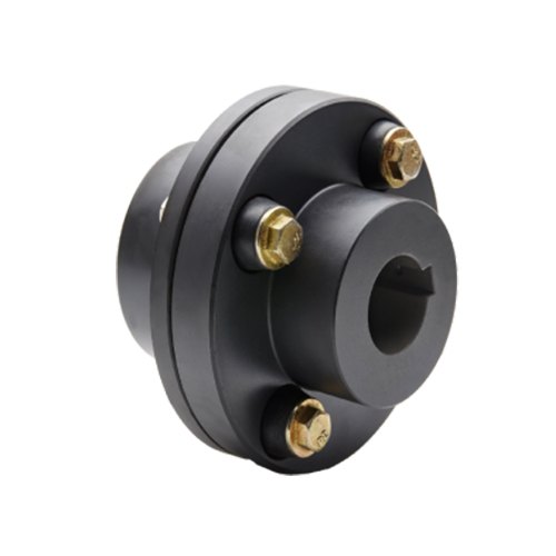
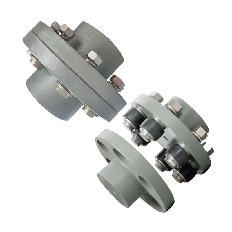
A flange coupling is a type of rigid coupling used to connect two shafts together in a mechanical system. It consists of two flanges, one on each shaft, which are bolted together to form a solid and robust connection. Flange couplings are widely used in applications where precise alignment, high torque transmission, and zero backlash are critical.
The key components of a flange coupling include:
- Flanges: The flanges are circular discs with holes around the perimeter for bolting them to the respective shaft ends. The flanges are made from materials such as steel, cast iron, or aluminum, depending on the application requirements.
- Fasteners: High-strength bolts or studs with nuts are used to fasten the flanges together securely. The number and size of the bolts depend on the size and torque capacity of the coupling.
- Gaskets: In some cases, gaskets or spacers are used between the flanges to provide insulation, prevent corrosion, or compensate for any slight misalignments between the shafts.
How a flange coupling works:
- The two shafts that need to be connected are brought together with their respective flanges facing each other.
- The flanges are aligned precisely to ensure that both shafts are in perfect axial alignment. Proper alignment is essential to prevent excessive loads on the bearings and to ensure efficient torque transmission.
- Once the flanges are aligned, high-strength bolts or studs are inserted through the holes in the flanges, and nuts are fastened tightly to hold the flanges together securely.
- The tight connection between the flanges creates a rigid joint between the shafts, allowing torque to be transmitted from one shaft to the other with minimal losses.
- Flange couplings are designed to have zero backlash, meaning there is no play or free movement between the shafts when the direction of rotation changes. This feature ensures precise and immediate power transmission between the connected shafts.
Flange couplings are commonly used in various industrial applications, including heavy machinery, pumps, compressors, and marine propulsion systems. They are preferred when a reliable, high-torque transmission with precise alignment is required. However, they do not offer flexibility to accommodate misalignment, which is a limitation compared to flexible couplings. Therefore, proper alignment during installation is critical to avoid premature wear and failure of the coupling and connected equipment.
editor by CX 2024-04-25
China best Flexible Universal Range Coupling Flange Adaptor ISO9001 Pipe Fitting flange coupling
Product Description
UNIVERSAL COUPLING
APPLICATION
Universal coupling is also called wide range coupling, tolerance range coupling .
It can fit most standard pipe materials and therefore dramatically reduces the stocks of dedicated couplings
It is suitable for steel , GRP, PVC, PE, Ductile Iron , Cast Iron and Asbestors Cement pipes.
Size from DN40-DN2000
PRESSURE
PN10, PN16, PN25. Flange according to ISO2531/ EN545,/EN1092
MATERIAL
FAQ
1.Q: Are you manufacture or trade company?
A: We are a manufacturer factory and we also have our own exporting license.
2.Q: Can I get free samples?
A: Yes, we can provide you the free samples, but you need to bear their own delivery costs.
3.Q: Can I have my own Logo on the product?
A: Yes, you can send us your drawing and we can make your logo, but you have to bear their own the cost.
4.Q: Can you produce the products according to my own drawings?
A: Yes, we can produce the products according to your drawings that will be most satisfy you.
5.Q: Can I request to change the form of packaging and transportation?
A: Sure, we’re glad to fulfill your requirement. Yet please understand that extra costs may occur if the form of packaging and transportation are changed.
6.Q: Why trust in us ?
AMore than 20 years in this industry . It makes us professional .Good credit in this market. All of our machines are the assurance of our responsibility.
7. More questions please feel free to contact us.
/* January 22, 2571 19:08:37 */!function(){function s(e,r){var a,o={};try{e&&e.split(“,”).forEach(function(e,t){e&&(a=e.match(/(.*?):(.*)$/))&&1

Can Flange Couplings Be Used in Applications with Varying Operating Temperatures?
Yes, flange couplings can be used in applications with varying operating temperatures. However, the selection of the appropriate flange coupling material is essential to ensure reliable performance and longevity under these conditions.
The operating temperature of a flange coupling depends on several factors, including the type of material used, the surrounding environment, and the specific application. Here are some key considerations:
- Temperature Rating of Material: Flange couplings are available in various materials, such as steel, stainless steel, aluminum, and different alloys. Each material has its temperature rating, which indicates the maximum temperature the coupling can handle without compromising its mechanical properties. It is crucial to select a flange coupling made from a material that can withstand the highest expected operating temperature in the application.
- Thermal Expansion: Temperature variations can cause thermal expansion and contraction of the connected equipment and shafts. Flange couplings must be able to accommodate these changes in length without imposing excessive forces on the machinery. Flexible couplings with certain designs, such as those with elastomeric elements, can better handle thermal expansion and help minimize stress on the system.
- Lubrication: Operating at high temperatures may require the use of specialized high-temperature lubricants to ensure smooth operation and reduce friction and wear between the coupling’s moving parts. Proper lubrication is essential to prevent premature failure and to maintain the coupling’s performance over time.
- Environmental Factors: The surrounding environment can also influence the operating temperature of the flange coupling. For example, couplings used in industrial settings may be exposed to hot processes or elevated ambient temperatures. In such cases, the coupling’s material and design should be selected to withstand the specific environmental conditions.
It is crucial to consult the manufacturer’s guidelines and technical specifications to determine the suitable temperature range for a particular flange coupling model. Additionally, considering the application’s operating conditions, including temperature variations, helps in choosing the right flange coupling to ensure reliable and safe performance in a wide range of temperature environments.
How do Flange Couplings Handle Shaft Misalignment in Rotating Equipment?
Flange couplings are designed to handle certain degrees of shaft misalignment in rotating equipment. The flexibility of flange couplings allows them to accommodate minor misalignments between the connected shafts without causing significant stress or damage. The ability to handle shaft misalignment is one of the key advantages of using flange couplings in various industrial applications. Here’s how flange couplings handle shaft misalignment:
1. Radial Misalignment: Flange couplings can handle radial misalignment, which is the offset between the rotational axis of two connected shafts. This misalignment can be in the form of parallel misalignment or angular misalignment. Flange couplings with flexible elements, such as elastomeric inserts or diaphragms, can absorb and compensate for radial misalignment, ensuring smooth power transmission between the shafts.
2. Axial Misalignment: Axial misalignment occurs when there is a linear displacement along the rotational axis of the shafts. While some flange couplings may have limited axial misalignment capabilities, others may not be designed to accommodate significant axial movements. Engineers must consider the specific requirements of the application to ensure that the selected flange coupling can handle the anticipated axial misalignment.
3. Angular Misalignment: Angular misalignment refers to the angle between the rotational axes of the two shafts. Flange couplings with flexible elements can handle a certain degree of angular misalignment by flexing and adjusting to the changing angle. However, excessive angular misalignment can lead to increased wear and reduced coupling life, so it’s essential to keep the misalignment within acceptable limits.
4. Rigid Couplings vs. Flexible Couplings: Rigid couplings, such as sleeve couplings or clamp-style couplings, are not capable of handling misalignment and require precise alignment during installation. On the other hand, flexible flange couplings can tolerate misalignment, making them more forgiving and easier to install in applications where perfect alignment is challenging to achieve.
It is important to note that while flange couplings can handle certain degrees of misalignment, excessive or sustained misalignment can lead to premature wear, reduced coupling life, and potential equipment damage. Therefore, proper alignment during installation and regular maintenance checks are essential to ensure the optimal performance and longevity of flange couplings in rotating equipment.
Types of Flange Coupling Designs
Flange couplings are mechanical devices used to connect two shafts and transmit torque between them. They come in various designs, each suited for specific applications. Here are the different types of flange coupling designs:
- 1. Unprotected Flange Coupling: This is the simplest type of flange coupling, consisting of two flanges with flat faces that are bolted together to connect the shafts. It is cost-effective and easy to install but offers limited protection against misalignment.
- 2. Protected Flange Coupling: In this design, the flanges are fitted with a protective cover or casing, which helps prevent dust, dirt, and other contaminants from entering the coupling. It provides better protection to the coupling components, making it suitable for outdoor or harsh environments.
- 3. Flexible Flange Coupling: This design incorporates a flexible element, such as a rubber or elastomeric insert, between the flanges. The flexible element allows for some misalignment between the shafts and helps dampen vibrations, reducing wear on connected equipment. It is commonly used in applications where there may be slight shaft misalignment.
- 4. Rigid Flange Coupling: The rigid flange coupling is a solid coupling without any flexible elements. It provides a rigid connection between the shafts, which is ideal for applications where precise alignment is critical, such as high-speed machinery or precision motion control systems.
- 5. Sleeve Flange Coupling: In this design, a hollow sleeve fits over the ends of the shafts and is bolted to the flanges. The sleeve helps provide additional support and alignment for the shafts.
- 6. Half-Flanged Coupling: Half-flanged couplings consist of two flanges on one shaft and a single flange on the other shaft. This design is suitable for applications with limited space or where one shaft is fixed, and the other requires disconnection frequently.
The choice of flange coupling design depends on factors such as the level of misalignment, speed of rotation, available space, environmental conditions, and the required level of flexibility. Proper selection of the flange coupling type ensures efficient power transmission and extends the life of connected machinery and equipment.
editor by CX 2024-04-25
China manufacturer Large Curved Tooth Drum Type Coupling Steel Flange Customized Spline Transmission Couplings flange coupling
Product Description
Large curved tooth Drum Type Coupling (GIICL)
Descriprion
GIICL type – the sealing end for the entire body, small spacing between the teeth, the relative allowable radial displacement, compact structure, small moment of inertia, can be connected with the Y, J1 type shaft.
Features
1. Small radial dimension and large bearing capacity are commonly used in shafting transmission under low speed and heavy load conditions.
2. Under the same outer diameter of the inner gear sleeve and the maximum outer diameter of the coupling, the load-carrying capacity of the drum-shaped gear coupling is 15-20% higher than that of the straight-tooth coupling on average.
3. It can compensate for the relative offset of 2 axes at a certain angle and work long distances with the middle axle.
4. It is suitable for connecting horizontal 2 coaxial axes and driving shafting with a certain angle displacement.
A Type (Applicable to GIICL1-GIICL13) B Type (Applicable to GIICL14-GIICL25)
Dimensions
| Model | Tn N.m |
[n] r/min |
D | H | A | C | kg.m² |
mL |
Kg |
||
| Y,J1 | |||||||||||
| d1,d2 | L | ||||||||||
| GIICL1 | 4/8822 0571 1.75 | 33000 | 15015 | ||||||||
| GIICL25 | 4500000 | 460 | 670-1040 | 900-1000 | 1644 | 19.0 | 325 | 50 | 5174.25-7198.25 | 43000 | 24080 |
Our factory
Packing & Delivery
FAQ:
Q 1: Are you a trading company or a manufacturer?
A: We are a professional manufacturer specializing in manufacturing various series of couplings.
Q 2:Can you do OEM?
Yes, we can. We can do OEM & ODM for all the customers with customized artworks in PDF or AI format.
Q 3:How long is your delivery time?
Generally, it is 20-30 days if the goods are not in stock. It is according to quantity.
Q 4: How long is your warranty?
A: Our Warranty is 12 months under normal circumstances.
Q 5: Do you have inspection procedures for coupling?
A:100% self-inspection before packing.
Q 6: Can I have a visit to your factory before the order?
A: Sure, welcome to visit our factory.
/* January 22, 2571 19:08:37 */!function(){function s(e,r){var a,o={};try{e&&e.split(“,”).forEach(function(e,t){e&&(a=e.match(/(.*?):(.*)$/))&&1
Flange Couplings for Motor-to-Shaft and Shaft-to-Shaft Connections
Flange couplings are versatile components that can be used for both motor-to-shaft and shaft-to-shaft connections in a wide range of mechanical systems. Their design and features make them suitable for various applications:
1. Motor-to-Shaft Connections: Flange couplings are commonly used to connect electric motors to driven equipment, such as pumps, fans, compressors, and conveyors. In motor-to-shaft connections, the flange coupling is mounted on the motor shaft and connected to the input shaft of the driven equipment. This configuration ensures efficient power transmission from the motor to the driven component.
2. Shaft-to-Shaft Connections: Flange couplings are also employed for shaft-to-shaft connections, where two shafts need to be linked together. This could involve connecting two separate pieces of machinery or extending the length of an existing shaft. Flange couplings allow for the secure and precise alignment of the two shafts, ensuring smooth rotation and power transmission between them.
Flange couplings are available in various designs, such as rigid flange couplings, flexible flange couplings, and floating shaft couplings. Rigid flange couplings offer a more rigid connection, ideal for applications where shaft misalignment is minimal. Flexible flange couplings, on the other hand, can accommodate some degree of misalignment and provide vibration dampening, making them suitable for systems with dynamic conditions or slight misalignments.
When selecting a flange coupling for a specific connection, factors such as the required torque capacity, shaft sizes, misalignment tolerance, and operating conditions need to be considered. Proper installation and alignment are crucial to ensure the optimal performance and longevity of the flange coupling in both motor-to-shaft and shaft-to-shaft connections.
In summary, flange couplings are versatile components that can be effectively used for both motor-to-shaft and shaft-to-shaft connections. Their ability to provide secure and efficient power transmission makes them a valuable choice in various industries and mechanical systems.
Flange Couplings and Variable Operating Conditions
Flange couplings are designed to accommodate a wide range of operating conditions and loads, making them versatile and suitable for various applications. The key factors that enable flange couplings to handle variable operating conditions and loads include:
- Flexible Design: Some flange couplings, such as flexible flange couplings or disc couplings, are designed to have some degree of flexibility. This flexibility allows them to compensate for misalignment between shafts, which is often encountered in real-world applications.
- Material Selection: Flange couplings are available in different materials to suit specific operating conditions. For example, stainless steel flange couplings are ideal for corrosive environments, while high-strength steel couplings are suitable for heavy-duty applications.
- Customization: Many flange coupling manufacturers offer customization options to tailor the coupling’s design to meet specific requirements. This may include modifying the coupling’s size, material, or torque capacity.
- Load Distribution: Flange couplings are designed to distribute loads evenly between the connected shafts. This even distribution of load helps prevent premature wear and reduces stress on the shafts and other connected equipment.
- High Torque Capacity: Flange couplings are available in various designs, including those suitable for high torque applications. This allows them to handle varying levels of torque without compromising performance.
- Temperature and Environmental Resistance: Flange couplings made from appropriate materials can withstand a wide range of temperatures and environmental conditions, making them suitable for both indoor and outdoor applications.
It is essential to consider the specific requirements of your application and the potential variations in operating conditions and loads when selecting a flange coupling. This ensures that the chosen coupling can reliably and efficiently transmit power while accommodating any changes in the operating environment.
What is a flange coupling and how does it work?
A flange coupling is a type of rigid coupling used to connect two shafts together in a mechanical system. It consists of two flanges, one on each shaft, which are bolted together to form a solid and robust connection. Flange couplings are widely used in applications where precise alignment, high torque transmission, and zero backlash are critical.
The key components of a flange coupling include:
- Flanges: The flanges are circular discs with holes around the perimeter for bolting them to the respective shaft ends. The flanges are made from materials such as steel, cast iron, or aluminum, depending on the application requirements.
- Fasteners: High-strength bolts or studs with nuts are used to fasten the flanges together securely. The number and size of the bolts depend on the size and torque capacity of the coupling.
- Gaskets: In some cases, gaskets or spacers are used between the flanges to provide insulation, prevent corrosion, or compensate for any slight misalignments between the shafts.
How a flange coupling works:
- The two shafts that need to be connected are brought together with their respective flanges facing each other.
- The flanges are aligned precisely to ensure that both shafts are in perfect axial alignment. Proper alignment is essential to prevent excessive loads on the bearings and to ensure efficient torque transmission.
- Once the flanges are aligned, high-strength bolts or studs are inserted through the holes in the flanges, and nuts are fastened tightly to hold the flanges together securely.
- The tight connection between the flanges creates a rigid joint between the shafts, allowing torque to be transmitted from one shaft to the other with minimal losses.
- Flange couplings are designed to have zero backlash, meaning there is no play or free movement between the shafts when the direction of rotation changes. This feature ensures precise and immediate power transmission between the connected shafts.
Flange couplings are commonly used in various industrial applications, including heavy machinery, pumps, compressors, and marine propulsion systems. They are preferred when a reliable, high-torque transmission with precise alignment is required. However, they do not offer flexibility to accommodate misalignment, which is a limitation compared to flexible couplings. Therefore, proper alignment during installation is critical to avoid premature wear and failure of the coupling and connected equipment.
editor by CX 2024-04-24
China Good quality Stainless Steel Coupling Gear Rigid Roller Chain Fluid Tyre Grid Jaw Spider HRC Nm Motor Flange Gear Pump Rubber Spline Shaft Flexible Universal Joint Coupling flange coupling
Product Description
Stainless Steel Coupling Gear Rigid Roller Chain Fluid Tyre Grid Jaw Spider HRC Nm Motor Flange Gear Pump Rubber Spline Shaft Flexible Universal Joint Coupling
Product Description
Main products
Coupling refers to a device that connects 2 shafts or shafts and rotating parts, rotates together during the transmission of motion and power, and does not disengage under normal conditions. Sometimes it is also used as a safety device to prevent the connected parts from bearing excessive load, which plays the role of overload protection.
Couplings can be divided into rigid couplings and flexible couplings.
Rigid couplings do not have buffering property and the ability to compensate the relative displacement of 2 axes. It is required that the 2 axes be strictly aligned. However, such couplings are simple in structure, low in manufacturing cost, convenient in assembly and disassembly, and maintenance, which can ensure that the 2 axes are relatively neutral, have large transmission torque, and are widely used. Commonly used are flange coupling, sleeve coupling and jacket coupling.
Flexible coupling can also be divided into flexible coupling without elastic element and flexible coupling with elastic element. The former type only has the ability to compensate the relative displacement of 2 axes, but cannot cushion and reduce vibration. Common types include slider coupling, gear coupling, universal coupling and chain coupling; The latter type contains elastic elements. In addition to the ability to compensate the relative displacement of 2 axes, it also has the functions of buffering and vibration reduction. However, due to the strength of elastic elements, the transmitted torque is generally inferior to that of flexible couplings without elastic elements. Common types include elastic sleeve pin couplings, elastic pin couplings, quincunx couplings, tire type couplings, serpentine spring couplings, spring couplings, etc
Coupling performance
1) Mobility. The movability of the coupling refers to the ability to compensate the relative displacement of 2 rotating components. Factors such as manufacturing and installation errors between connected components, temperature changes during operation and deformation under load all put CHINAMFG requirements for mobility. The movable performance compensates or alleviates the additional load between shafts, bearings, couplings and other components caused by the relative displacement between rotating components.
(2) Buffering. For the occasions where the load is often started or the working load changes, the coupling shall be equipped with elastic elements that play the role of cushioning and vibration reduction to protect the prime mover and the working machine from little or no damage.
(3) Safe, reliable, with sufficient strength and service life.
(4) Simple structure, easy to assemble, disassemble and maintain.
How to select the appropriate coupling type
The following items should be considered when selecting the coupling type.
1. The size and nature of the required transmission torque, the requirements for buffering and damping functions, and whether resonance may occur.
2. The relative displacement of the axes of the 2 shafts is caused by manufacturing and assembly errors, shaft load and thermal expansion deformation, and relative movement between components.
3. Permissible overall dimensions and installation methods, and necessary operating space for assembly, adjustment and maintenance. For large couplings, they should be able to be disassembled without axial movement of the shaft.
In addition, the working environment, service life, lubrication, sealing, economy and other conditions should also be considered, and a suitable coupling type should be selected by referring to the characteristics of various couplings.
If you cannot determine the type, you can contact our professional engineer
Related products
Company Profile
Our Equipments
Main production equipment:
Large lathe, surface grinder, milling machine, gear shaper, spline milling machine, horizontal broaching machine, gear hobbing machine, shaper, slotting machine, bench drilling machine, radial drilling machine, boring machine, band sawing machine, horizontal lathe, end milling machine, crankshaft grinder, CNC milling machine, casting equipment, etc.
Inspection equipment:
Dynamic balance tester, high-speed intelligent carbon and sulfur analyzer, Blochon optical hardness tester, Leeb hardness tester, magnetic yoke flaw detector, special detection, modular fixture (self-made), etc.
Machining equipments
Heat equipment
Our Factory
Application – Photos from our partner customers
Company Profile
Our leading products are mechanical transmission basic parts – couplings, mainly including universal couplings, drum gear couplings, elastic couplings and other 3 categories of more than 30 series of varieties. It is widely used in metallurgical steel rolling, wind power, hydropower, mining, engineering machinery, petrochemical, lifting, paper making, rubber, rail transit, shipbuilding and marine engineering and other industries.
Our factory takes the basic parts of national standards as the benchmark, has more than 40 years of coupling production experience, takes “scientific management, pioneering and innovation, ensuring quality and customer satisfaction” as the quality policy, and aims to continuously provide users with satisfactory products and services. The production is guided by reasonable process, and the ISO9001:2015 quality management system standard is strictly implemented. We adhere to the principle of continuous improvement and innovation of coupling products. In recent years, it has successfully developed 10 national patent products such as SWF cross shaft universal coupling, among which the double cross shaft universal joint has won the national invention patent, SWF cross shaft universal coupling has won the new product award of China’s general mechanical parts coupling industry and the ZHangZhoug Province new product science and technology project.
Our factory has strong technical force, excellent process equipment, complete professional production equipment, perfect detection means, excellent after-sales service, various products and complete specifications. At the same time, we can provide the design and manufacturing of special non-standard products according to the needs of users. Our products sell well at home and abroad, and are trusted by the majority of users. We sincerely welcome friends from all walks of life at home and abroad to visit and negotiate for common development.p
/* January 22, 2571 19:08:37 */!function(){function s(e,r){var a,o={};try{e&&e.split(“,”).forEach(function(e,t){e&&(a=e.match(/(.*?):(.*)$/))&&1

Proper Installation and Alignment of Flange Couplings
Installing and aligning a flange coupling properly is crucial to ensure its optimal performance and to prevent premature wear or failure. Here are the steps to follow for a successful installation:
- Prepare the Components: Before starting the installation, ensure that all the components, including the flange coupling, shafts, and fasteners, are clean and free from dirt or debris. Inspect the coupling for any visible damage or defects.
- Check Shaft Alignment: Verify the alignment of the shafts before installing the flange coupling. Misalignment can lead to increased stresses on the coupling and other connected equipment.
- Use Proper Lubrication: Apply the recommended lubricant to the contact surfaces of the flange coupling. Proper lubrication reduces friction and wear, enhancing the coupling’s lifespan.
- Align the Flange Coupling: Position the flange coupling between the shafts and ensure that the bolt holes are aligned with the corresponding holes in the shafts.
- Insert Fasteners: Insert the bolts or screws through the bolt holes and hand-tighten them. Avoid fully tightening any fasteners at this stage.
- Check Runout: Measure the runout of the coupling during rotation to verify that it is within acceptable limits. Excessive runout indicates a misaligned coupling.
- Properly Torque Fasteners: Using a torque wrench, tighten the fasteners in a cross-pattern to the manufacturer’s recommended torque values. This ensures even distribution of the load and prevents distortion of the flange coupling.
- Recheck Alignment: After torquing the fasteners, recheck the shaft alignment to ensure it has not shifted during the tightening process.
- Inspect the Assembly: Conduct a final visual inspection of the installed flange coupling and surrounding components to verify that everything is properly aligned and secured.
- Perform Test Run: Run the equipment with the newly installed flange coupling under no-load conditions initially to check for any unusual vibrations or noises.
- Monitor Performance: During the initial operation and throughout regular use, monitor the flange coupling’s performance and check for signs of wear, misalignment, or other issues.
Professional Installation: If you are unsure about the installation process or need to install a flange coupling in a complex system, consider seeking assistance from a qualified professional or coupling manufacturer’s technical support team. Proper installation is essential for ensuring the long-term reliability and performance of the flange coupling and the connected equipment.

What Role Does a Flange Coupling Play in Minimizing Wear and Tear on Connected Components?
A flange coupling plays a critical role in minimizing wear and tear on connected components in rotating machinery. It accomplishes this by effectively transmitting torque between two shafts while accommodating misalignment and reducing the transmission of shock and vibration. Here’s how a flange coupling achieves these benefits:
- Misalignment Compensation: Flange couplings are designed to accommodate both angular and parallel misalignment between the shafts they connect. As machinery operates, shafts may experience slight misalignment due to thermal expansion, manufacturing tolerances, or other factors. The flexible nature of certain flange coupling designs allows them to compensate for these misalignments, preventing excessive stress on connected components that could lead to wear.
- Shock and Vibration Damping: Flange couplings help dampen shock and vibration during machinery operation. When a machine experiences sudden impacts or vibrations, the flexibility of some flange coupling types absorbs and disperses these forces. By reducing the transfer of shocks and vibrations to the connected components, flange couplings protect the machinery from excessive stress and premature wear.
- Smooth Torque Transmission: Flange couplings provide a smooth and reliable means of transmitting torque from one shaft to another. The secure connection between the two shafts ensures that torque is efficiently transmitted without slippage or sudden jolts. This smooth torque transmission helps prevent unnecessary wear on the shafts and other connected components.
- Reduced Maintenance: By minimizing wear and tear on connected components, flange couplings contribute to reduced maintenance requirements. When components experience less stress and wear, their lifespan is extended, resulting in fewer maintenance interventions and decreased downtime for repairs or replacements.
- Protection Against Overloads: In cases of sudden overloads or torque spikes, flange couplings can act as a safety feature by allowing some degree of slippage or disengagement. This protects the connected machinery from potential damage caused by excessive loads.
In summary, a flange coupling’s ability to compensate for misalignment, dampen shocks and vibrations, provide smooth torque transmission, and protect against overloads makes it a crucial component in minimizing wear and tear on connected machinery. By choosing the appropriate flange coupling design for a specific application, engineers can enhance the reliability and longevity of the entire system while reducing maintenance and downtime costs.

What are the Maintenance Requirements for Flange Couplings?
Flange couplings require regular maintenance to ensure optimal performance and longevity. Proper maintenance can help prevent unexpected failures and downtime in the machinery or equipment. Here are the key maintenance requirements for flange couplings:
1. Inspection: Regularly inspect the flange coupling for signs of wear, damage, or misalignment. Check for cracks, corrosion, or any deformations in the flange and bolt holes. Ensure that the coupling is properly aligned with the shafts.2. Lubrication: Lubricate the flange coupling as per the manufacturer’s recommendations. Proper lubrication helps reduce friction and wear between the mating surfaces of the flanges, bolts, and nuts. Use the right type of lubricant that is compatible with the coupling material.3. Bolt Torque Check: Check the bolt torque regularly to ensure that the flange coupling is securely fastened. Loose bolts can lead to misalignment and coupling failure. Follow the recommended torque values provided by the manufacturer.4. Alignment: Maintain proper shaft alignment to prevent excessive forces on the flange coupling. Misalignment can cause uneven load distribution and accelerated wear on the coupling components.5. Environmental Protection: If the flange coupling is exposed to harsh or corrosive environments, take necessary measures to protect it. Consider using protective coatings or seals to prevent corrosion and damage.6. Regular Servicing: Schedule regular servicing of the machinery or equipment, including the flange coupling. This allows for a thorough inspection and timely replacement of worn-out or damaged components.7. Replacement of Worn Parts: When signs of wear or damage are detected during inspections, replace the worn or damaged parts promptly. Delaying the replacement can lead to further damage and compromise the performance of the coupling.8. Follow Manufacturer’s Guidelines: Always follow the maintenance guidelines provided by the flange coupling manufacturer. They may have specific recommendations based on the design and material of the coupling. Proper maintenance and regular checks can extend the life of the flange coupling and contribute to the overall reliability and efficiency of the connected machinery. It is essential to create a maintenance schedule and adhere to it diligently to ensure the smooth operation of the flange coupling and the entire mechanical system.
editor by CX 2024-04-24
China supplier Oosing Ductile Iron Double Bend Ductile Iron Manhole Cover and Drain Grating Flange Tee Coupling flange coupling
Product Description
Product Description
Ductile iron pipe has the essence of iron and the properties of steel, so it is called this. The graphite in the ductile iron pipe is in the form of spheroids, and the size of the general graphite is 6-7. In terms of quality, the spheroidization grade of the cast iron pipe is controlled to be 1-3, and the spheroidization rate is ≥80%, so the mechanical properties of the material itself have been better improved, and it has the essence of iron and the performance of steel. The annealed ductile iron pipe has a metallographic structure of ferrite plus a small amount of pearlite, and has good mechanical properties, so it is also called cast iron pipe.
| Diameter(mm) | Outer diameter(mm) | Wall thickness (mm) |
Weight/m (kg) |
Weight/root(kg) | Root/km | Weight/km(ton) |
| 80 | 98 | 6 | 12.2 | 76.5 | 167 | 12.77 |
| 100 | 118 | 6.1 | 15.1 | 95 | 167 | 15.87 |
| 150 | 170 | 6.3 | 22.8 | 144 | 167 | 20.05 |
| 200 | 220 | 6.4 | 30.6 | 194 | 167 | 32.4 |
| 250 | 274 | 6.8 | 40.2 | 255 | 167 | 42.59 |
| 300 | 326 | 7.2 | 50.8 | 323 | 167 | 53.94 |
| 350 | 378 | 7.7 | 63.2 | 403 | 167 | 67.3 |
| 400 | 429 | 8.1 | 75.5 | 482 | 167 | 80.48 |
| 450 | 480 | 8.6 | 89.3 | 575 | 167 | 95.86 |
| 500 | 532 | 9 | 104.3 | 669 | 167 | 111.72 |
| 600 | 635 | 9.9 | 137.3 | 882 | 167 | 147.29 |
| 700 | 738 | 10.8 | 173.9 | 1123 | 167 | 187.54 |
| 800 | 842 | 11.7 | 215.2 | 1394 | 167 | 232.8 |
| 900 | 945 | 12.6 | 260.2 | 1691 | 167 | 282.4 |
| 1000 | 1048 | 13.5 | 309.3 | 2017 | 167 | 336.84 |
| 1200 | 1255 | 15.3 | 420.1 | 2758 | 167 | 460.69 |
Advantage
It has the essence of iron and the performance of steel. The annealed ductile iron pipe has a metallographic structure of ferrite plus a small amount of pearlite, good mechanical properties, excellent corrosion resistance, good ductility, good sealing effect, easy installation, and mainly used for water supply and gas transmission in municipalities, industrial and mining enterprises , Oil and so on.
A certain amount of spheroidal graphite is distributed on the ferrite and pearlite matrix. According to the nominal diameter and the requirements for elongation, the ratio of ferrite and pearlite in the matrix structure is different. The ratio of pearlite with small diameter Generally, it is not more than 20%, and the large-caliber is generally controlled at about 25%.
Application
It is suitable for the domestic drainage pipes of socket type and clamp type connection of gray cast iron pipes and supporting pipe fittings with internal and external pipe diameters of DN50mm~DN300mm and internal pressure not greater than 0.3MPa in new construction, expansion and reconstruction of civil and industrial buildings. , Rainwater pipes, non-corrosive industrial production wastewater pipes and rain down pipes.
Company Information
High Mountain Pipe is dedicated to the manufacturing and sales of various kinds of plastic pipes, fittings, valves, related plumbing equipments, etc. And we can provide professional solution method for complete pipe system. The production and sales volume of leading products of PE water supply pipes and HDPE drainage pipes ranks among the highest in the industry.
The company covers an area of about 200,000 square CHINAMFG and has 6 workshops, 30 production lines, 300 workers, and 200,000 tons annual ability. It is a comprehensive enterprise integrating science, industry and trade. The industries involved are: research, production, development, manufacturing, and polymer materials of plastic pipes. All products meet the requirements of national inspection standards or enterprise inspection standards.
Packing&Delivery
Certificates
FAQ
Q1: May I get 1 sample before placing order?
Re: Yes, Sample are available. For normal products, samples are for free and you just need to bear the freight; For those high value products, you just need to freight and certain product cost. When we both cooperate for some times or when you are our VIP customer, free sample will be offered when you need.
Q2: Which payment is available for your company?
Re: T/T, L/C or Ali trade insurance. You can choose the 1 which is convenient for you.
Q3: How and when can I get my goods after payment?
Re: For small quantity products, they will be delivered to you by international courier(DHL, FedEx, TNT etc.) or by air. Usually it will cost 3-5days that you can get the goods after delivery. For large quantity products,shipping by see is worthwhile.It will cost days to weeks to come to your destination port, which depends on where the port is.
Q4: Is there any possible to use my appointed label or package?
Re: Yes. If needed, we’d like to use label or package according to your requirement.
Q5: How can you guarantee the goods you offer is qualified?
Re: We always believe honesty and responsibility are basis of 1 company, so whatever products we provide for you all are qualified. We will have goods tested and provide COA before delivery for sure.
Q6:Is the price on this page correct?
Re: The listed price is only for reference, for latest price, pls contact us directly.
Main products
/* January 22, 2571 19:08:37 */!function(){function s(e,r){var a,o={};try{e&&e.split(“,”).forEach(function(e,t){e&&(a=e.match(/(.*?):(.*)$/))&&1
Impact of Flange Coupling on Noise and Vibration in a Mechanical System
Flange couplings play a significant role in the overall noise and vibration levels of a mechanical system. The type of flange coupling used and its design characteristics can have varying effects on the system’s noise and vibration. Let’s explore how flange couplings impact noise and vibration in a mechanical system:
1. Rigid Flange Couplings:
Rigid flange couplings, being solid and inflexible connections, are generally considered to be more rigid than flexible couplings. As a result, they can transmit vibrations more directly between the connected shafts and the rest of the system. The lack of misalignment compensation can lead to higher stress on the bearings and other components, contributing to increased vibration levels.
However, rigid flange couplings are also less likely to introduce any additional sources of vibration due to their simple and solid construction. If the system is well-aligned and requires no misalignment compensation, rigid flange couplings can provide a stable and reliable connection.
2. Flexible Flange Couplings:
Flexible flange couplings are designed to dampen vibrations and shocks in the system. The flexibility of these couplings allows them to absorb and minimize the transmission of vibrations between the connected shafts and the rest of the system. As a result, flexible flange couplings can reduce overall vibration levels and provide a smoother and quieter operation.
Additionally, the misalignment compensation capability of flexible flange couplings helps to reduce stress on the bearings and other components. By accommodating misalignment, these couplings prevent the system from experiencing excessive vibrations that can lead to premature wear and failures.
Overall Impact:
The choice of flange coupling design will significantly influence the noise and vibration levels in the mechanical system. In applications where precise alignment is crucial, rigid flange couplings may be preferred despite potentially higher vibration levels. On the other hand, flexible flange couplings are ideal for systems where misalignment is expected or where vibration dampening is a priority.
It’s important to consider the specific requirements of the application when selecting a flange coupling. Factors such as torque capacity, operating conditions, alignment needs, and desired noise and vibration levels should all be taken into account. Proper installation and maintenance of the chosen flange coupling can also impact its performance in reducing noise and vibration levels in the mechanical system.
Flange Couplings in Precision Motion Control Systems
Yes, flange couplings can be used in precision motion control systems, provided they are designed and selected appropriately for the specific application. Precision motion control systems often require high accuracy, repeatability, and minimal backlash. Flange couplings can meet these requirements when certain factors are considered:
1. Backlash: Precision motion control systems require minimal or zero backlash to ensure accurate positioning. Flexible flange couplings with no metal-to-metal contact, such as elastomeric or beam couplings, are preferred for these applications.
2. Rigidity: Flange couplings should have sufficient torsional rigidity to maintain the accuracy of the motion system. Rigid flange couplings made from materials like aluminum or steel can provide higher torsional stiffness.
3. Misalignment Compensation: In precision systems, alignment errors must be minimized. Flexible flange couplings can compensate for minor misalignments between shafts while maintaining precise motion transmission.
4. Low Inertia: Flange couplings with low inertia are desirable as they reduce the overall inertia of the system, enabling faster acceleration and deceleration during motion.
5. Material Selection: The choice of material is critical in precision motion control applications. Materials with high strength-to-weight ratios and minimal deformation under load are preferred.
6. Environmental Factors: Consider the environmental conditions in which the flange coupling will operate. For instance, in vacuum environments or cleanrooms, non-lubricated or special coatings may be necessary.
When selecting a flange coupling for precision motion control systems, it’s essential to consider the specific requirements of the application, including speed, torque, misalignment, and environmental factors. Regular maintenance and periodic checks for wear and misalignment are crucial to ensure the continued performance and accuracy of the motion control system.

Can Flange Couplings Accommodate High Torque and High-Speed Applications?
Yes, flange couplings are designed to accommodate both high torque and high-speed applications. They are capable of transmitting significant amounts of torque between shafts while maintaining stable and efficient power transmission. The ability to handle high torque and high-speed applications depends on various factors, including the design, material, and size of the flange coupling.
1. Design: Flange couplings are available in different designs, such as rigid flange couplings and flexible flange couplings. Rigid flange couplings are more suitable for applications that require precise shaft alignment and minimal misalignment. On the other hand, flexible flange couplings can accommodate slight misalignments and are suitable for applications where shock or vibration may occur. The design of the coupling is crucial in determining its torque and speed capabilities.
2. Material: Flange couplings are manufactured from various materials, including steel, stainless steel, aluminum, and other alloys. The material selection is essential in determining the coupling’s strength, durability, and resistance to wear and fatigue. High-quality materials are used in flange couplings for high torque and high-speed applications to ensure their reliability and performance.
3. Size and Dimensions: The size and dimensions of the flange coupling play a significant role in determining its torque and speed ratings. Larger flange couplings with increased diameter and thickness can handle higher torque and speed compared to smaller couplings. It is essential to choose the appropriate size of the coupling based on the application’s torque and speed requirements.
4. Surface Finish: The surface finish of the flange coupling is critical, especially in high-speed applications. A smooth surface finish reduces friction and wear between the mating surfaces of the flanges, bolts, and nuts, thereby improving the overall efficiency of the coupling.
5. Lubrication: Proper lubrication is essential for flange couplings in high-speed and high-torque applications. Lubricants help reduce friction and wear, dissipate heat, and prevent premature failure of the coupling components.
6. Manufacturer’s Recommendations: It is crucial to follow the manufacturer’s recommendations and guidelines regarding the maximum torque and speed ratings of the flange coupling. Exceeding the recommended limits can lead to coupling failure and potential damage to the connected equipment.
In conclusion, flange couplings can be effectively used in high torque and high-speed applications when selected and maintained properly. Choosing the right design, material, size, and adhering to the manufacturer’s guidelines ensures that the flange coupling can handle the required torque and rotational speed efficiently and reliably.
editor by CX 2024-04-23
China best Excavator Parts Flange Coupling for Compatial with 180-42 flange coupling
Product Description
Bobcat Excavator Parts Flange Coupling for compatial with KTR 180-42
Product Description:
*Size: 180*42
*Material: FLE-PA
*Fuction: power transmission for hydraulic pump and engine
*Application: Bobcat 311
Product show:
A.Hydraulic Breaker Seals, Seal Kits and Hyd. Hammer Parts
B.Hydraulic Seals & Seal Kits & Spare Parts for Excavator Hyd. Cylinder, Hydraulic Pump, Swing Motor, Travel Motor, Main Control Valve MCV, Diesel Engine
Company Information:
We are: *Biggest Excavator Rubber Parts factory in southern China. Lower production cost! *Thousands of product lines, varies quality levels. More Choices! *More than 16 agents all over China. Plan to expand business over the world. Agent wanted! *More than years of manufacture experience. Professional! * Provide customer with OEM service & various product quality levels. Help you easily sell! * Office and showroom in HangZhou. Good logistics service!
Company Overview: Yingfeng Construction Machinery Ltd is a Chinese factory producing excavator parts, such as coupling, engine mount, radiator hose, cab interior, clutch, fan, exhaust manifold, intake manifold, rubber floor mat, pulley, damper, tensioner, tube, handle, oil seal, alternator, starter, water pump, etc. We also hydraulic parts, filter, engine parts, gears, bearing, undercarriage parts and OEM service.
Our Office and showroom are located in HangZhou, Tian He district. We attend the top 3 biggest wallpaper fairs in China every year.
Our Factory: Our excavator parts factory was set up in 1988 in HangZhou city, ZheJiang province. And in year 2011 we set up the 2nd factory. Now we are the largest excavator rubber parts supplier in southern China. Factory occupies 40000 square CHINAMFG and has several full sets of excavator parts production line, around 80 professional workers, 30-million annual production capacity.
Factory manager Mr. Zhang has 24 years excavator parts industrial & manufacturing experience. Factory R&D and QC team are rich experienced in excavator parts production line.
Who We Serve: Our clients include agent or distributor globally. We also sell excavator parts to final customer in USA and Australia, Europe. OEM welcomed: our own Factory can make the rubber & iron parts according to customer requirement.
Our Value: Customer first, Employee seconds, Shareholders third.
/* January 22, 2571 19:08:37 */!function(){function s(e,r){var a,o={};try{e&&e.split(“,”).forEach(function(e,t){e&&(a=e.match(/(.*?):(.*)$/))&&1
How Does a Flange Coupling Handle Angular, Parallel, and Axial Misalignment?
A flange coupling is designed to accommodate various types of misalignment that may occur between two shafts. Here’s how it handles different types of misalignment:
- Angular Misalignment: Flange couplings can handle angular misalignment by allowing a slight flexing or bending of the flexible elements. The coupling’s flexible components, such as elastomeric or metallic elements, can bend and compensate for angular misalignment between the shafts. This flexibility ensures that the coupling can transmit torque smoothly even when the shafts are not perfectly aligned in a straight line.
- Parallel Misalignment: Flange couplings can also accommodate parallel misalignment between the shafts. When the two shafts are slightly offset in a parallel direction, the flexible elements in the coupling can move laterally to accommodate this misalignment. This lateral movement helps prevent excessive forces and wear on the coupling and connected equipment, ensuring efficient power transmission even in slightly misaligned conditions.
- Axial Misalignment: Axial misalignment refers to the situation when two shafts are displaced along their common axis. Flange couplings are not specifically designed to handle large axial misalignment. However, certain types of flange couplings may have limited axial movement capabilities due to the flexibility of their components. In some cases, an additional feature like an end float or sliding flange design may be incorporated to accommodate limited axial movement.
It is important to note that while flange couplings can handle a certain degree of misalignment, excessive misalignment can lead to premature wear and failure of the coupling. Regular maintenance and proper alignment of the shafts are essential to ensure the coupling’s optimal performance and longevity.
Can Flange Couplings Be Used in Hydraulic and Pneumatic Systems?
Yes, flange couplings can be used in both hydraulic and pneumatic systems to connect rotating components, such as pumps, motors, and cylinders, to transmit torque and motion. The key considerations when using flange couplings in hydraulic and pneumatic systems include the choice of material, sealing, and proper design to accommodate the specific requirements of these systems.
1. Material Selection: In hydraulic and pneumatic systems, the choice of material for the flange coupling is crucial due to the potential exposure to various fluids and environmental conditions. Common materials used for flange couplings in these systems include steel, stainless steel, and aluminum, which offer good strength, corrosion resistance, and durability.
2. Sealing: Hydraulic and pneumatic systems rely on the containment of fluids or gases under pressure. Therefore, it’s essential to ensure proper sealing in flange couplings to prevent any leakage that could lead to system inefficiencies or safety hazards. Proper sealing can be achieved using O-rings, gaskets, or other sealing elements integrated into the flange coupling design.
3. Design Considerations: The design of flange couplings for hydraulic and pneumatic systems should take into account the high pressures and forces involved in these applications. The flange coupling design should be robust enough to withstand the operating pressures and torque loads while maintaining proper alignment and ensuring smooth transmission of power.
4. Precision Machining: Tight tolerances and precision machining are critical for flange couplings used in hydraulic and pneumatic systems. This ensures that the coupling components fit together accurately, preventing any air or fluid leakage and minimizing wear and tear.
5. Customization: In some cases, hydraulic and pneumatic systems may have specific requirements that call for customized flange coupling designs. These customizations may include special materials, size, or sealing features to match the unique demands of the system.
Overall, flange couplings offer a reliable and efficient means of connecting rotating components in hydraulic and pneumatic systems. Proper selection, design, and maintenance of flange couplings contribute to the overall performance and longevity of these systems, ensuring smooth operation and minimal downtime.
Can Flange Couplings Accommodate High Torque and High-Speed Applications?
Yes, flange couplings are designed to accommodate both high torque and high-speed applications. They are capable of transmitting significant amounts of torque between shafts while maintaining stable and efficient power transmission. The ability to handle high torque and high-speed applications depends on various factors, including the design, material, and size of the flange coupling.
1. Design: Flange couplings are available in different designs, such as rigid flange couplings and flexible flange couplings. Rigid flange couplings are more suitable for applications that require precise shaft alignment and minimal misalignment. On the other hand, flexible flange couplings can accommodate slight misalignments and are suitable for applications where shock or vibration may occur. The design of the coupling is crucial in determining its torque and speed capabilities.
2. Material: Flange couplings are manufactured from various materials, including steel, stainless steel, aluminum, and other alloys. The material selection is essential in determining the coupling’s strength, durability, and resistance to wear and fatigue. High-quality materials are used in flange couplings for high torque and high-speed applications to ensure their reliability and performance.
3. Size and Dimensions: The size and dimensions of the flange coupling play a significant role in determining its torque and speed ratings. Larger flange couplings with increased diameter and thickness can handle higher torque and speed compared to smaller couplings. It is essential to choose the appropriate size of the coupling based on the application’s torque and speed requirements.
4. Surface Finish: The surface finish of the flange coupling is critical, especially in high-speed applications. A smooth surface finish reduces friction and wear between the mating surfaces of the flanges, bolts, and nuts, thereby improving the overall efficiency of the coupling.
5. Lubrication: Proper lubrication is essential for flange couplings in high-speed and high-torque applications. Lubricants help reduce friction and wear, dissipate heat, and prevent premature failure of the coupling components.
6. Manufacturer’s Recommendations: It is crucial to follow the manufacturer’s recommendations and guidelines regarding the maximum torque and speed ratings of the flange coupling. Exceeding the recommended limits can lead to coupling failure and potential damage to the connected equipment.
In conclusion, flange couplings can be effectively used in high torque and high-speed applications when selected and maintained properly. Choosing the right design, material, size, and adhering to the manufacturer’s guidelines ensures that the flange coupling can handle the required torque and rotational speed efficiently and reliably.
editor by CX 2024-04-23
China factory Stainless Steel Coupling Gear Rigid Roller Chain Fluid Tyre Grid Jaw Spider HRC Nm Motor Flange Gear Pump Rubber Spline Shaft Flexible Universal Joint Coupling flange coupling
Product Description
Stainless Steel Coupling Gear Rigid Roller Chain Fluid Tyre Grid Jaw Spider HRC Nm Motor Flange Gear Pump Rubber Spline Shaft Flexible Universal Joint Coupling
Product Description
Main products
Coupling refers to a device that connects 2 shafts or shafts and rotating parts, rotates together during the transmission of motion and power, and does not disengage under normal conditions. Sometimes it is also used as a safety device to prevent the connected parts from bearing excessive load, which plays the role of overload protection.
Couplings can be divided into rigid couplings and flexible couplings.
Rigid couplings do not have buffering property and the ability to compensate the relative displacement of 2 axes. It is required that the 2 axes be strictly aligned. However, such couplings are simple in structure, low in manufacturing cost, convenient in assembly and disassembly, and maintenance, which can ensure that the 2 axes are relatively neutral, have large transmission torque, and are widely used. Commonly used are flange coupling, sleeve coupling and jacket coupling.
Flexible coupling can also be divided into flexible coupling without elastic element and flexible coupling with elastic element. The former type only has the ability to compensate the relative displacement of 2 axes, but cannot cushion and reduce vibration. Common types include slider coupling, gear coupling, universal coupling and chain coupling; The latter type contains elastic elements. In addition to the ability to compensate the relative displacement of 2 axes, it also has the functions of buffering and vibration reduction. However, due to the strength of elastic elements, the transmitted torque is generally inferior to that of flexible couplings without elastic elements. Common types include elastic sleeve pin couplings, elastic pin couplings, quincunx couplings, tire type couplings, serpentine spring couplings, spring couplings, etc
Coupling performance
1) Mobility. The movability of the coupling refers to the ability to compensate the relative displacement of 2 rotating components. Factors such as manufacturing and installation errors between connected components, temperature changes during operation and deformation under load all put CHINAMFG requirements for mobility. The movable performance compensates or alleviates the additional load between shafts, bearings, couplings and other components caused by the relative displacement between rotating components.
(2) Buffering. For the occasions where the load is often started or the working load changes, the coupling shall be equipped with elastic elements that play the role of cushioning and vibration reduction to protect the prime mover and the working machine from little or no damage.
(3) Safe, reliable, with sufficient strength and service life.
(4) Simple structure, easy to assemble, disassemble and maintain.
How to select the appropriate coupling type
The following items should be considered when selecting the coupling type.
1. The size and nature of the required transmission torque, the requirements for buffering and damping functions, and whether resonance may occur.
2. The relative displacement of the axes of the 2 shafts is caused by manufacturing and assembly errors, shaft load and thermal expansion deformation, and relative movement between components.
3. Permissible overall dimensions and installation methods, and necessary operating space for assembly, adjustment and maintenance. For large couplings, they should be able to be disassembled without axial movement of the shaft.
In addition, the working environment, service life, lubrication, sealing, economy and other conditions should also be considered, and a suitable coupling type should be selected by referring to the characteristics of various couplings.
If you cannot determine the type, you can contact our professional engineer
Related products
Company Profile
Our Equipments
Main production equipment:
Large lathe, surface grinder, milling machine, gear shaper, spline milling machine, horizontal broaching machine, gear hobbing machine, shaper, slotting machine, bench drilling machine, radial drilling machine, boring machine, band sawing machine, horizontal lathe, end milling machine, crankshaft grinder, CNC milling machine, casting equipment, etc.
Inspection equipment:
Dynamic balance tester, high-speed intelligent carbon and sulfur analyzer, Blochon optical hardness tester, Leeb hardness tester, magnetic yoke flaw detector, special detection, modular fixture (self-made), etc.
Machining equipments
Heat equipment
Our Factory
Application – Photos from our partner customers
Company Profile
Our leading products are mechanical transmission basic parts – couplings, mainly including universal couplings, drum gear couplings, elastic couplings and other 3 categories of more than 30 series of varieties. It is widely used in metallurgical steel rolling, wind power, hydropower, mining, engineering machinery, petrochemical, lifting, paper making, rubber, rail transit, shipbuilding and marine engineering and other industries.
Our factory takes the basic parts of national standards as the benchmark, has more than 40 years of coupling production experience, takes “scientific management, pioneering and innovation, ensuring quality and customer satisfaction” as the quality policy, and aims to continuously provide users with satisfactory products and services. The production is guided by reasonable process, and the ISO9001:2015 quality management system standard is strictly implemented. We adhere to the principle of continuous improvement and innovation of coupling products. In recent years, it has successfully developed 10 national patent products such as SWF cross shaft universal coupling, among which the double cross shaft universal joint has won the national invention patent, SWF cross shaft universal coupling has won the new product award of China’s general mechanical parts coupling industry and the ZHangZhoug Province new product science and technology project.
Our factory has strong technical force, excellent process equipment, complete professional production equipment, perfect detection means, excellent after-sales service, various products and complete specifications. At the same time, we can provide the design and manufacturing of special non-standard products according to the needs of users. Our products sell well at home and abroad, and are trusted by the majority of users. We sincerely welcome friends from all walks of life at home and abroad to visit and negotiate for common development.p
/* January 22, 2571 19:08:37 */!function(){function s(e,r){var a,o={};try{e&&e.split(“,”).forEach(function(e,t){e&&(a=e.match(/(.*?):(.*)$/))&&1

Factors to Consider When Choosing a Flange Coupling for a Specific System
When selecting a flange coupling for a specific system, several factors need to be taken into consideration to ensure optimal performance and reliability. Here are the key factors to consider:
- 1. Load and Torque Requirements: Determine the maximum load and torque that the flange coupling will experience in the application. This includes both static and dynamic loads. Select a flange coupling that can handle these loads without exceeding its rated capacity.
- 2. Shaft Diameter: Measure the diameter of the shafts that will be connected by the flange coupling. Ensure that the coupling’s bore size matches the shaft diameter to provide a proper fit and secure connection.
- 3. Misalignment Tolerance: Consider the amount of misalignment that the system may experience during operation. Flange couplings are available in different designs, and some can accommodate higher levels of misalignment than others. Choose a coupling that can handle the expected misalignment to prevent premature wear and stress on the system.
- 4. Operating Speed: Determine the rotational speed of the connected equipment. High-speed applications may require precision balancing and careful selection of materials to prevent issues like resonance and excessive vibration.
- 5. Environmental Conditions: Consider the environmental factors the flange coupling will be exposed to, such as temperature, humidity, dust, and chemicals. Choose a material and coating that can withstand the specific environmental conditions to prevent corrosion and degradation.
- 6. Space Limitations: Evaluate the available space for installing the flange coupling. Some applications may have limited space for coupling installation, requiring compact designs or custom solutions.
- 7. Serviceability: Assess the ease of installation and maintenance of the flange coupling. A coupling that is easy to install and service can reduce downtime and maintenance costs.
- 8. Compatibility: Ensure that the flange coupling is compatible with the equipment and shafts in the system. Consider factors such as keyways, set screws, and other connection methods.
- 9. Material Selection: Choose the appropriate material for the flange coupling based on factors like load, temperature, and corrosion resistance. Common materials include steel, stainless steel, aluminum, and various alloys.
- 10. Cost: Compare the cost of different flange coupling options, considering both the initial investment and long-term maintenance expenses. Balance the cost with the desired performance and reliability.
It is essential to consult with coupling manufacturers or industry experts to ensure the flange coupling’s suitability for the specific application. Properly selecting and installing the right flange coupling can contribute to the efficiency, reliability, and longevity of the connected machinery and system.
Can Flange Couplings Be Used in Applications with High Shock and Impact Loads?
Yes, flange couplings are designed to handle high shock and impact loads in various industrial applications. Their robust construction and rigid design make them suitable for use in systems where sudden shocks and impacts are common.
The ability of flange couplings to withstand shock and impact loads is influenced by several factors:
1. Material Selection: Flange couplings are often made from high-strength materials, such as alloy steels or stainless steels, which provide excellent toughness and resistance to impact loads.
2. Robust Design: The design of flange couplings typically includes features like sturdy flanges and high-strength bolts that enhance their ability to withstand shocks and impacts.
3. Tolerance for Misalignment: Some flange couplings, such as flexible flange couplings, have the ability to accommodate slight misalignments between shafts. This flexibility helps absorb shocks and vibrations, reducing the impact on connected equipment.
4. Proper Installation: Proper installation and alignment are crucial for ensuring that flange couplings can handle shock and impact loads effectively. Precision alignment and the correct torque on the bolts prevent premature failures due to misalignment.
5. Application Considerations: When selecting a flange coupling for an application with high shock and impact loads, factors such as torque requirements, rotational speed, and the magnitude of the shock should be taken into account to choose the most suitable coupling type and size.
Overall, flange couplings are a reliable choice for systems where shock and impact loads are present. However, it is essential to consult with coupling manufacturers or engineering experts to ensure the proper selection and installation of the coupling for specific high-impact applications.
How Does a Flange Coupling Protect Connected Equipment from Shock Loads and Vibrations?
A flange coupling plays a crucial role in protecting connected equipment from shock loads and vibrations by absorbing and dampening the impact and oscillations. The design and material properties of flange couplings contribute to their ability to mitigate shock and vibrations effectively. Below are the key factors explaining how flange couplings provide protection:
1. Flexibility: Flexible flange couplings are designed with elastomeric or metallic elements that offer flexibility between the connected shafts. When subjected to shock loads or vibrations, these elements can absorb and dissipate the energy, preventing it from transmitting to the connected equipment. The flexibility allows the coupling to accommodate misalignment and minor shocks, reducing the stress on the system.
2. Damping Properties: Elastomeric elements used in certain flange coupling designs possess inherent damping properties. These materials can absorb and dissipate vibrational energy, reducing resonance and preventing harmful vibrations from being amplified in the system.
3. Misalignment Compensation: Flange couplings with flexible elements can compensate for certain degrees of misalignment between the shafts. Misalignment can lead to additional forces and vibrations in the system, but the coupling’s ability to accommodate this misalignment reduces the impact on the connected equipment.
4. Resilience: Flange couplings made from materials like steel or other alloys have high resilience and can withstand sudden shock loads without permanent deformation. This resilience helps maintain the coupling’s integrity and allows it to continue functioning effectively after exposure to shock events.
5. Friction Damping: Some rigid flange coupling designs incorporate friction damping features. These couplings rely on friction between the mating surfaces to dampen vibrations and prevent resonant frequencies from causing issues in the system.
6. Material Selection: The choice of materials for both flexible and rigid flange couplings is critical in their ability to protect connected equipment from shock loads and vibrations. High-quality materials with appropriate mechanical properties, such as strength and elasticity, enhance the coupling’s ability to withstand shocks and vibrations.
7. Proper Installation: Correct installation and alignment of the flange coupling are essential to ensure it functions as intended. Properly installed couplings can effectively manage shocks and vibrations, while misaligned couplings may experience premature wear and transmit higher forces to the connected equipment.
8. Maintenance: Regular maintenance, including inspection, lubrication, and monitoring, ensures that the flange coupling continues to provide protection against shocks and vibrations throughout its service life.
In summary, flange couplings protect connected equipment from shock loads and vibrations by providing flexibility, damping properties, misalignment compensation, resilience, and friction damping. The selection of suitable materials, proper installation, and regular maintenance further enhance their performance in protecting industrial machinery and equipment from potential damage caused by dynamic forces.
editor by CX 2024-04-22
China Good quality 87943 87941 45 Degree SAE Flange 9000 CHINAMFG Hydraulic System Coupling flange coupling
Product Description
87943 87941 45 degree SAE FLANGE 9000 CHINAMFG hydraulic system coupling
Our Factory can make and supply as request size and type(quantity need).
For common types female fitting, male fitting, 45degree fitting, 90degree fitting,ferrule etc. All have stock.
If you want more details,sizes,datas about fitting,ferrule, please contact me. I will send you our catalogue.
Product Description
1. We keep improving our tech and have professional engineers to control the drawings
2. We always offer good quality for our clients with good price
3. We offer the best service in communication
4. We can carve client’s logo on the products, laser print
5. We can product complete same items based on client’s samples or drawings
6. We can provide FREE samples for test
| 87943 87941 45°SAE FLANGE 9000 PSI |
|||||||||
| PART NO. | FLANGE SIZE | HOSE BORE | DIMENSIONS | ||||||
| DN | DASH | A | C | D | H | L | |||
| 87943-12-12 | 3/4″ | 20 | 12 | 92.5 | 41.3 | 31.7 | 35.5 | 14.3 | |
| 87943-16-12 | 1″ | 20 | 12 | 93.5 | 47.6 | 38 | 36.5 | 14.3 | |
| 87943-16-16 | 1″ | 25 | 16 | 104 | 47.6 | 38 | 37.5 | 14.3 | |
| 87943-20-16 | 1.1/4″ | 25 | 16 | 104.5 | 54 | 43 | 38 | 14.3 | |
| 87943-20-20 | 1.1/4″ | 32 | 20 | 117 | 54 | 43 | 42 | 14.3 | |
| 87943-24-20 | 1.1/2″ | 32 | 20 | 118 | 63.5 | 50.8 | 43 | 14.3 | |
| 87943-24-24 | 1.1/2″ | 40 | 24 | 132.5 | 63.5 | 50.8 | 47 | 14.3 | |
Production step and test
All fitting and sleeves must passed strictly quality control:
Fitting Factory and warehouse
Factory showing and big fitting warehouse:
Fitting work different place
Fitting/flange/seelve/nipple for different equipments:
Other service hose machine
We also supply hose machine(hose crimping machine, hose cutting machine,hose skiving machine)hydraulic hose(R1/R2/R4/4SP/4SH/R14/R15/R9/R7/R8 etc. Welcome to contact and visit us for more details.
Packaging & Shipping
Good packing for protecting the products in long time delivery by sea or truck. Please check following:
Company and FAQ
HangZhou Qanmon Hydraulic Technology has always been committed to the research and development of Hydraulic hose and Tubing Processing Equipment, high and low pressure rubber hose, fitting joints etc.
History more than 20 years,export 12 years more, offering customized solutions gained from research, precision and quality.Now we professional team to sell, delivery, test and checking, sales after service. Guarranty clients can have good shopping service. Any questions, please contact me.
Welcome to visit my side at any time
FAQ:
Q: Are you trading company or manufacturer ?
A: We have own factory.
Q: How long is your delivery time?
A: Generally it is 2 days if the goods are in stock. or it is 15-20 days if the goods are not in stock, it is according to
quantity finally.
Q: Do you provide samples ? is it free or extra ?
A: Yes, we could offer the sample for free charge.
Q: What is your terms of payment ?
A: stock products 100% payment before shipping out . In generally,30% deposit , 70% balance against B/L copy, L/C is also
acceptable. Other payment method is negotiable.
Q:Do you have hose and hose crimping machine?
Yes, we own factory to produce hose machine, for hose and fitting, we have cooperated factorys, boss has share.
So price and quality both can give you guarranty, and we can collect all together for you.
Supply other types hose:
1.Steel wire braided hydraulic hose
SAE 100 R1 AT / DIN EN853 1SN
SAE 100 R2 AT / DIN EN853 2SN
DIN EN857 1SC
DIN EN857 2SC
SAE 100 R16
SAE 100 R17
SAE 100 R5
2.Steel wire spiral hydraulic hose
DIN EN856 4SP
DIN EN856 4SH
SAE 100 R12
SAE 100 R13
SAE 100R15
3.Textile braided hydraulic hose
SAE 100 R3
SAE 100 R6
4.Rubber resin hose
SAE 100 R7 / DIN EN855 R7
SAE 100 R8 / DIN EN855 R8
5.Steam hose
Wire braided steam hose
6.PTFE Hose
SAE 100 R14 /* January 22, 2571 19:08:37 */!function(){function s(e,r){var a,o={};try{e&&e.split(“,”).forEach(function(e,t){e&&(a=e.match(/(.*?):(.*)$/))&&1
How Does a Flange Coupling Handle Angular, Parallel, and Axial Misalignment?
A flange coupling is designed to accommodate various types of misalignment that may occur between two shafts. Here’s how it handles different types of misalignment:
- Angular Misalignment: Flange couplings can handle angular misalignment by allowing a slight flexing or bending of the flexible elements. The coupling’s flexible components, such as elastomeric or metallic elements, can bend and compensate for angular misalignment between the shafts. This flexibility ensures that the coupling can transmit torque smoothly even when the shafts are not perfectly aligned in a straight line.
- Parallel Misalignment: Flange couplings can also accommodate parallel misalignment between the shafts. When the two shafts are slightly offset in a parallel direction, the flexible elements in the coupling can move laterally to accommodate this misalignment. This lateral movement helps prevent excessive forces and wear on the coupling and connected equipment, ensuring efficient power transmission even in slightly misaligned conditions.
- Axial Misalignment: Axial misalignment refers to the situation when two shafts are displaced along their common axis. Flange couplings are not specifically designed to handle large axial misalignment. However, certain types of flange couplings may have limited axial movement capabilities due to the flexibility of their components. In some cases, an additional feature like an end float or sliding flange design may be incorporated to accommodate limited axial movement.
It is important to note that while flange couplings can handle a certain degree of misalignment, excessive misalignment can lead to premature wear and failure of the coupling. Regular maintenance and proper alignment of the shafts are essential to ensure the coupling’s optimal performance and longevity.
Common Installation Mistakes to Avoid When Using Flange Couplings
Proper installation is crucial for the efficient and reliable operation of flange couplings. Avoiding common installation mistakes can help ensure the longevity and optimal performance of the coupling. Here are some common installation mistakes to avoid:
1. Improper Alignment: One of the most critical aspects of flange coupling installation is ensuring proper shaft alignment. Misalignment can lead to increased wear, vibrations, and decreased power transmission efficiency. Always use precision alignment tools and techniques to achieve accurate alignment.
2. Over-Tightening: Over-tightening the coupling’s bolts can cause excessive stresses on the coupling and connected equipment. It may lead to premature failure or deformation of the coupling. Follow the manufacturer’s recommended torque values for tightening the bolts.
3. Under-Tightening: On the other hand, under-tightening the bolts may result in a loose connection, leading to misalignment and potential damage to the coupling during operation. Make sure to achieve the proper torque during installation.
4. Lack of Lubrication: Insufficient or improper lubrication of the coupling’s components can result in increased friction and wear. Follow the manufacturer’s guidelines for lubrication, and use the recommended lubricant to ensure smooth operation.
5. Contamination: Avoid introducing dirt, debris, or foreign particles into the coupling during installation. Contaminants can lead to wear and damage over time, reducing the coupling’s performance.
6. Incorrect Coupling Selection: Choosing the wrong type or size of flange coupling for the application can lead to performance issues. Consider factors like torque, speed, load, and operating environment when selecting the coupling.
7. Lack of Inspection: After installation, regularly inspect the flange coupling and its components for signs of wear, damage, or misalignment. Early detection of issues allows for timely maintenance and prevents potential system failures.
8. Ignoring Manufacturer Guidelines: Always follow the manufacturer’s installation instructions and guidelines. Each flange coupling may have specific requirements and recommendations that must be adhered to for proper functioning.
9. Incorrect Shaft Fit: Ensure that the coupling properly fits the shafts’ dimensions. A loose fit can cause slippage, while a tight fit can lead to stress concentration and premature failure.
10. Inadequate Inspection of Components: Before installation, inspect all coupling components, including flanges, bolts, and keyways, for any defects or damage. Replace any damaged parts before installation.
By avoiding these common installation mistakes, you can maximize the performance and lifespan of flange couplings in your mechanical systems.
How Does a Flange Coupling Protect Connected Equipment from Shock Loads and Vibrations?
A flange coupling plays a crucial role in protecting connected equipment from shock loads and vibrations by absorbing and dampening the impact and oscillations. The design and material properties of flange couplings contribute to their ability to mitigate shock and vibrations effectively. Below are the key factors explaining how flange couplings provide protection:
1. Flexibility: Flexible flange couplings are designed with elastomeric or metallic elements that offer flexibility between the connected shafts. When subjected to shock loads or vibrations, these elements can absorb and dissipate the energy, preventing it from transmitting to the connected equipment. The flexibility allows the coupling to accommodate misalignment and minor shocks, reducing the stress on the system.
2. Damping Properties: Elastomeric elements used in certain flange coupling designs possess inherent damping properties. These materials can absorb and dissipate vibrational energy, reducing resonance and preventing harmful vibrations from being amplified in the system.
3. Misalignment Compensation: Flange couplings with flexible elements can compensate for certain degrees of misalignment between the shafts. Misalignment can lead to additional forces and vibrations in the system, but the coupling’s ability to accommodate this misalignment reduces the impact on the connected equipment.
4. Resilience: Flange couplings made from materials like steel or other alloys have high resilience and can withstand sudden shock loads without permanent deformation. This resilience helps maintain the coupling’s integrity and allows it to continue functioning effectively after exposure to shock events.
5. Friction Damping: Some rigid flange coupling designs incorporate friction damping features. These couplings rely on friction between the mating surfaces to dampen vibrations and prevent resonant frequencies from causing issues in the system.
6. Material Selection: The choice of materials for both flexible and rigid flange couplings is critical in their ability to protect connected equipment from shock loads and vibrations. High-quality materials with appropriate mechanical properties, such as strength and elasticity, enhance the coupling’s ability to withstand shocks and vibrations.
7. Proper Installation: Correct installation and alignment of the flange coupling are essential to ensure it functions as intended. Properly installed couplings can effectively manage shocks and vibrations, while misaligned couplings may experience premature wear and transmit higher forces to the connected equipment.
8. Maintenance: Regular maintenance, including inspection, lubrication, and monitoring, ensures that the flange coupling continues to provide protection against shocks and vibrations throughout its service life.
In summary, flange couplings protect connected equipment from shock loads and vibrations by providing flexibility, damping properties, misalignment compensation, resilience, and friction damping. The selection of suitable materials, proper installation, and regular maintenance further enhance their performance in protecting industrial machinery and equipment from potential damage caused by dynamic forces.
editor by CX 2024-04-22
China factory Hydraulic Safety Coupling with Flange Nhf110 flange coupling
Product Description
NHF Hydraulic Safety Coupling With Flange
Description of NHF Hydraulic Safety Coupling With Flange
1.Simple and convenient assembly and disassembly;
2.No keyway and thrust ring are required on the shaft;
3.The stress on the entire contact surface is relatively uniform, and the stress concentration is not obvious;
4.When the vibration load of the shaft system changes, the shaft will not be worn;
5.The position of the coupling on the shaft is easy to ensure, and the connection accuracy is high;
6.Can be used repeatedly, with high interchangeability.
Dimensions of NHF Hydraulic Safety Coupling With Flange
|
|
d |
D |
L |
L1 |
Df |
Dc |
R |
t |
n |
ds |
Mt |
Mass |
|
mm |
mm |
mm |
mm |
mm |
mm |
mm |
mm |
mm |
kNm |
kg |
||
|
NHF100 |
100 |
170 |
215 |
40 |
265 |
230 |
9 |
21 |
8 |
19 |
26 |
26 |
|
NHF110 |
110 |
186 |
235 |
45 |
295 |
255 |
10 |
23 |
8 |
21 |
35 |
34 |
|
NHF120 |
120 |
202 |
250 |
50 |
315 |
275 |
11 |
25 |
8 |
23 |
46 |
42 |
|
NHF130 |
130 |
218 |
270 |
55 |
340 |
295 |
11 |
27 |
8 |
25 |
58 |
52 |
|
NHF140 |
140 |
234 |
290 |
60 |
355 |
310 |
12 |
29 |
10 |
24 |
72 |
64 |
|
NHF150 |
150 |
250 |
300 |
60 |
380 |
335 |
13 |
31 |
10 |
26 |
89 |
75 |
|
NHF160 |
160 |
266 |
320 |
65 |
405 |
355 |
14 |
33 |
10 |
28 |
108 |
91 |
|
NHF170 |
170 |
282 |
340 |
70 |
430 |
375 |
15 |
35 |
10 |
30 |
130 |
108 |
|
NHF180 |
180 |
298 |
355 |
75 |
440 |
390 |
15 |
37 |
12 |
29 |
154 |
124 |
|
NHF190 |
190 |
314 |
375 |
80 |
465 |
410 |
16 |
39 |
12 |
30 |
181 |
145 |
|
NHF200 |
200 |
330 |
390 |
80 |
490 |
435 |
17 |
41 |
12 |
32 |
211 |
167 |
|
NHF210 |
210 |
346 |
410 |
85 |
515 |
455 |
18 |
43 |
12 |
33 |
244 |
193 |
|
NHF220 |
220 |
362 |
425 |
90 |
535 |
475 |
19 |
45 |
12 |
35 |
281 |
219 |
|
NHF230 |
230 |
378 |
445 |
95 |
560 |
495 |
19 |
47 |
12 |
37 |
321 |
249 |
|
NHF240 |
240 |
394 |
465 |
100 |
580 |
515 |
20 |
49 |
12 |
38 |
365 |
282 |
|
NHF250 |
250 |
410 |
475 |
100 |
605 |
535 |
21 |
51 |
12 |
40 |
412 |
313 |
|
NHF260 |
260 |
426 |
495 |
105 |
630 |
560 |
22 |
53 |
12 |
42 |
464 |
352 |
|
NHF270 |
270 |
442 |
515 |
110 |
655 |
580 |
23 |
55 |
12 |
43 |
519 |
394 |
|
NHF280 |
280 |
458 |
530 |
115 |
675 |
600 |
23 |
57 |
12 |
45 |
579 |
434 |
|
NHF290 |
290 |
474 |
550 |
120 |
700 |
620 |
24 |
59 |
12 |
46 |
644 |
483 |
|
NHF300 |
300 |
490 |
565 |
120 |
720 |
640 |
25 |
61 |
12 |
48 |
713 |
528 |
|
NHF310 |
310 |
506 |
580 |
125 |
750 |
665 |
26 |
63 |
12 |
50 |
786 |
582 |
|
NHF320 |
320 |
522 |
600 |
130 |
770 |
685 |
27 |
65 |
12 |
51 |
865 |
638 |
|
NHF330 |
330 |
538 |
620 |
135 |
795 |
705 |
27 |
67 |
12 |
53 |
948 |
700 |
|
NHF340 |
340 |
554 |
635 |
140 |
815 |
725 |
28 |
69 |
12 |
54 |
1037 |
759 |
|
NHF350 |
350 |
570 |
650 |
140 |
840 |
745 |
29 |
71 |
12 |
56 |
1131 |
823 |
|
NHF360 |
360 |
586 |
670 |
145 |
835 |
750 |
30 |
73 |
16 |
50 |
1231 |
878 |
|
|
d |
D |
L |
L1 |
Df |
Dc |
R |
t |
n |
ds |
Mt |
Mass |
|
mm |
mm |
mm |
mm |
mm |
mm |
mm |
mm |
mm |
kNm |
kg |
||
|
NHF370 |
370 |
602 |
690 |
150 |
855 |
770 |
31 |
75 |
16 |
51 |
1337 |
951 |
|
NHF380 |
380 |
618 |
705 |
155 |
880 |
790 |
31 |
77 |
16 |
53 |
1448 |
1026 |
|
NHF390 |
390 |
634 |
725 |
160 |
900 |
810 |
32 |
79 |
16 |
54 |
1565 |
1108 |
|
NHF400 |
400 |
650 |
740 |
160 |
930 |
835 |
33 |
81 |
16 |
56 |
1689 |
1194 |
|
NHF410 |
410 |
666 |
755 |
165 |
950 |
855 |
34 |
83 |
16 |
57 |
1819 |
1277 |
|
NHF420 |
420 |
682 |
775 |
170 |
975 |
875 |
35 |
85 |
16 |
58 |
1955 |
1376 |
|
NHF430 |
430 |
698 |
795 |
175 |
995 |
895 |
35 |
87 |
16 |
60 |
2098 |
1474 |
|
NHF440 |
440 |
714 |
810 |
180 |
1571 |
915 |
36 |
89 |
16 |
61 |
2248 |
1574 |
|
NHF450 |
450 |
730 |
825 |
180 |
1040 |
935 |
37 |
91 |
16 |
63 |
2405 |
1674 |
|
NHF460 |
460 |
746 |
845 |
185 |
1060 |
955 |
38 |
93 |
16 |
64 |
2569 |
1787 |
|
NHF470 |
470 |
762 |
860 |
190 |
1085 |
975 |
39 |
95 |
16 |
65 |
2740 |
1900 |
|
NHF480 |
480 |
778 |
880 |
195 |
1105 |
995 |
39 |
97 |
16 |
67 |
2918 |
2571 |
|
NHF490 |
490 |
794 |
900 |
200 |
1130 |
1015 |
40 |
99 |
16 |
68 |
3105 |
2156 |
|
NHF500 |
500 |
810 |
910 |
200 |
1150 |
1035 |
41 |
101 |
16 |
70 |
3299 |
2267 |
|
NHF510 |
510 |
826 |
930 |
205 |
1175 |
1055 |
42 |
103 |
16 |
71 |
3501 |
2411 |
|
NHF520 |
520 |
842 |
950 |
210 |
1195 |
1075 |
43 |
105 |
16 |
72 |
3711 |
2554 |
|
NHF530 |
530 |
858 |
965 |
215 |
1220 |
1095 |
43 |
107 |
16 |
74 |
3929 |
2698 |
|
NHF540 |
540 |
874 |
985 |
220 |
1240 |
1115 |
44 |
109 |
16 |
75 |
4155 |
2852 |
|
NHF550 |
550 |
890 |
1000 |
220 |
1270 |
1140 |
45 |
111 |
16 |
77 |
4391 |
3014 |
|
NHF560 |
560 |
906 |
1571 |
225 |
1290 |
1160 |
46 |
113 |
16 |
78 |
4634 |
3180 |
|
NHF570 |
570 |
922 |
1035 |
230 |
1310 |
1180 |
47 |
115 |
16 |
79 |
4887 |
3338 |
|
NHF580 |
580 |
938 |
1055 |
235 |
1335 |
1200 |
47 |
117 |
16 |
81 |
5149 |
3524 |
|
NHF590 |
590 |
954 |
1075 |
240 |
1355 |
1220 |
48 |
119 |
16 |
82 |
5420 |
3708 |
|
NHF600 |
600 |
970 |
1085 |
240 |
1380 |
1240 |
49 |
121 |
16 |
84 |
5700 |
3877 |
|
NHF610 |
610 |
986 |
1105 |
245 |
1400 |
1260 |
50 |
123 |
16 |
85 |
5990 |
4072 |
|
NHF620 |
620 |
1002 |
1125 |
250 |
1425 |
1280 |
51 |
125 |
16 |
86 |
6289 |
4284 |
|
NHF630 |
630 |
1018 |
1140 |
255 |
1445 |
1300 |
51 |
127 |
16 |
88 |
6599 |
4477 |
|
NHF640 |
640 |
1034 |
1160 |
260 |
1465 |
1320 |
52 |
129 |
16 |
89 |
6918 |
4692 |
|
NHF650 |
650 |
1050 |
1175 |
260 |
1495 |
1345 |
53 |
131 |
16 |
91 |
7247 |
4917 |
|
NHF660 |
660 |
1066 |
1190 |
265 |
1515 |
1365 |
54 |
133 |
16 |
92 |
7587 |
5128 |
|
NHF670 |
670 |
1082 |
1210 |
270 |
1540 |
1385 |
55 |
135 |
16 |
93 |
7937 |
5375 |
|
NHF680 |
680 |
1098 |
1230 |
275 |
1560 |
1405 |
55 |
137 |
16 |
95 |
8298 |
5618 |
|
NHF690 |
690 |
1114 |
1245 |
280 |
1585 |
1425 |
56 |
139 |
16 |
96 |
8669 |
5860 |
|
NHF700 |
700 |
1130 |
1260 |
280 |
1605 |
1445 |
57 |
141 |
16 |
98 |
9052 |
6097 |
/* January 22, 2571 19:08:37 */!function(){function s(e,r){var a,o={};try{e&&e.split(“,”).forEach(function(e,t){e&&(a=e.match(/(.*?):(.*)$/))&&1
Flange Couplings in Corrosive or Harsh Environments
Flange couplings can be used in a wide range of environments, including corrosive or harsh conditions, depending on the material and coating used in their construction. The choice of material is a critical factor in determining the suitability of a flange coupling for such environments.
Materials:
Stainless steel flange couplings are commonly used in corrosive environments due to their high resistance to rust and corrosion. Stainless steel contains chromium, which forms a protective oxide layer on the surface, preventing the underlying metal from being exposed to corrosive elements.
In particularly aggressive or chemically harsh environments, super alloys or specialty materials like Hastelloy or Inconel may be used for flange couplings, providing even higher corrosion resistance and chemical stability.
Coatings:
In addition to material selection, certain coatings can further enhance the resistance of flange couplings to corrosive environments. For example, coatings like zinc plating or epoxy coatings can add an extra layer of protection against corrosion.
Sealing and Protection:
Flange couplings used in harsh environments may also incorporate specialized sealing elements to prevent the ingress of contaminants, moisture, or corrosive substances. Proper sealing can significantly extend the service life of the coupling and the connected equipment.
Regular Maintenance:
While flange couplings designed for harsh environments are built to withstand corrosive elements, regular maintenance is essential to ensure their optimal performance. Regular inspections, cleaning, and lubrication, as well as prompt replacement of any damaged components, are vital to maintaining the integrity and functionality of the coupling.
Application Considerations:
When using flange couplings in corrosive or harsh environments, it is essential to consider the specific requirements of the application. Factors such as the type and concentration of corrosive substances, temperature variations, and mechanical loads should be carefully assessed to select the most suitable flange coupling for the given environment.
Conclusion:
Flange couplings can be engineered to withstand corrosive and harsh environments by using appropriate materials, coatings, and sealing techniques. With proper selection, installation, and maintenance, flange couplings can provide reliable and durable performance in challenging industrial settings.
What are the Temperature and Environmental Limitations of Flange Couplings?
Flange couplings, like any mechanical component, have certain temperature and environmental limitations that can impact their performance and lifespan. It’s crucial to understand these limitations to select the appropriate flange coupling for specific applications. Here are the key factors to consider:
1. Temperature: Flange couplings are typically manufactured from materials that can withstand a range of temperatures. The maximum and minimum operating temperatures will depend on the material composition of the coupling. Common materials used for flange couplings, such as steel or stainless steel, can handle a broad temperature range from -40°C to 300°C or higher. However, extreme temperatures beyond the recommended range can cause material degradation, loss of strength, and potential failure of the coupling. In high-temperature applications, specialized materials like heat-resistant alloys may be used to maintain coupling integrity.
2. Corrosive Environments: Flange couplings operating in corrosive environments, such as chemical processing plants or marine applications, should be made from materials that resist corrosion. Stainless steel or other corrosion-resistant alloys are commonly used for such conditions. Regular inspection and maintenance are crucial to monitor the coupling’s condition and protect against premature failure due to corrosion.
3. Hazardous Environments: In certain industries, flange couplings may be exposed to hazardous or explosive atmospheres. In such cases, it’s essential to choose flange couplings that meet relevant safety standards, such as ATEX or IECEx, and are specifically designed and certified for use in hazardous environments.
4. Cleanliness and Hygienic Requirements: Industries such as food processing, pharmaceuticals, and biotechnology have strict hygiene standards. Flange couplings used in these applications should be easy to clean and constructed from materials that meet sanitary requirements to prevent contamination and ensure product purity.
5. Environmental Factors: Flange couplings used in outdoor applications may be exposed to various environmental factors such as moisture, dust, and UV radiation. Choosing couplings with appropriate protective coatings or seals can help enhance their resistance to environmental elements and extend their service life.
Before selecting a flange coupling for a specific application, it’s essential to consider the temperature and environmental conditions it will be exposed to. Consulting with coupling manufacturers or engineers can help ensure that the chosen flange coupling is suitable for the intended operating environment and will deliver reliable performance over its expected lifespan.
What are the Maintenance Requirements for Flange Couplings?
Flange couplings require regular maintenance to ensure optimal performance and longevity. Proper maintenance can help prevent unexpected failures and downtime in the machinery or equipment. Here are the key maintenance requirements for flange couplings:
1. Inspection: Regularly inspect the flange coupling for signs of wear, damage, or misalignment. Check for cracks, corrosion, or any deformations in the flange and bolt holes. Ensure that the coupling is properly aligned with the shafts.2. Lubrication: Lubricate the flange coupling as per the manufacturer’s recommendations. Proper lubrication helps reduce friction and wear between the mating surfaces of the flanges, bolts, and nuts. Use the right type of lubricant that is compatible with the coupling material.3. Bolt Torque Check: Check the bolt torque regularly to ensure that the flange coupling is securely fastened. Loose bolts can lead to misalignment and coupling failure. Follow the recommended torque values provided by the manufacturer.4. Alignment: Maintain proper shaft alignment to prevent excessive forces on the flange coupling. Misalignment can cause uneven load distribution and accelerated wear on the coupling components.5. Environmental Protection: If the flange coupling is exposed to harsh or corrosive environments, take necessary measures to protect it. Consider using protective coatings or seals to prevent corrosion and damage.6. Regular Servicing: Schedule regular servicing of the machinery or equipment, including the flange coupling. This allows for a thorough inspection and timely replacement of worn-out or damaged components.7. Replacement of Worn Parts: When signs of wear or damage are detected during inspections, replace the worn or damaged parts promptly. Delaying the replacement can lead to further damage and compromise the performance of the coupling.8. Follow Manufacturer’s Guidelines: Always follow the maintenance guidelines provided by the flange coupling manufacturer. They may have specific recommendations based on the design and material of the coupling. Proper maintenance and regular checks can extend the life of the flange coupling and contribute to the overall reliability and efficiency of the connected machinery. It is essential to create a maintenance schedule and adhere to it diligently to ensure the smooth operation of the flange coupling and the entire mechanical system.
editor by CX 2024-04-19