
The service factor is the single most important number in coupling selection ¡ª more important than the nominal torque, more important than the bore diameter, and more important than the coupling type. It is the multiplier that translates the calculated running torque into the design torque the coupling must actually handle, accounting for every real operating load that exceeds the steady-state value. Miscalculating the service factor is the most common reason correctly sized couplings fail prematurely. This guide explains what the service factor accounts for, how to calculate it correctly for the most common Australian industrial applications, and how the choice of coupling type ¡ª such as a flexible tyre coupling versus a heavy-duty shaft coupling ¡ª interacts with the service factor to give the final coupling specification.
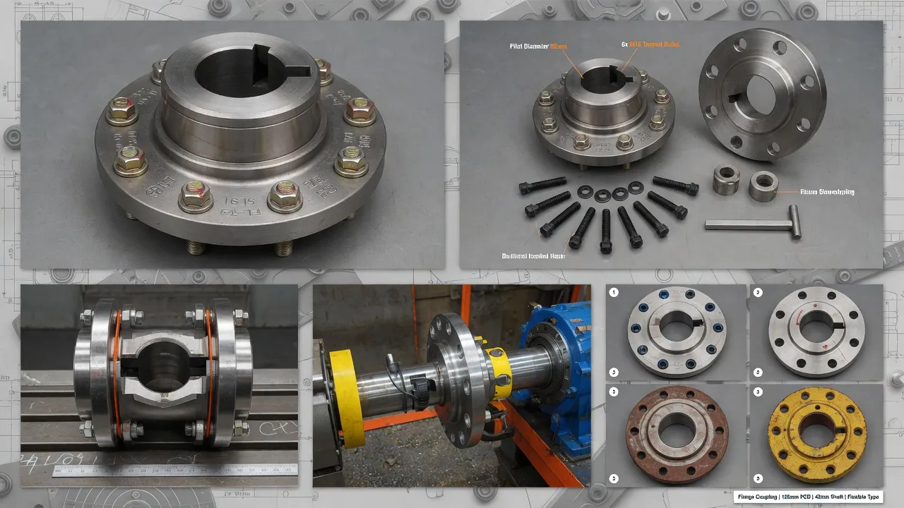
What the Service Factor Actually Represents
The nominal running torque calculated from motor power and speed (T = 9,550 ¡Á kW ¡Â RPM) represents the steady-state average torque under rated load at rated speed. In real industrial operations, the coupling is never only exposed to this value. Starting torque peaks, load variations, shock events, and fatigue cycling all produce torque excursions above the nominal value ¡ª sometimes briefly, sometimes sustained. The service factor is a multiplier that ensures the coupling is rated to handle these peaks reliably throughout its intended service life.
A service factor of 1.5 means the coupling is rated for 1.5 times the nominal running torque ¡ª providing a 50% margin above the calculated average for peaks, shock, and fatigue. A service factor of 3.0 means a 200% margin ¡ª necessary when the application involves heavy shock loading from crushers, mills, or reciprocating machinery where peak torque can momentarily reach 3¨C4 times the running value.
Service Factor Table ¡ª Australian Industrial Applications
| Driven Machine Type | Load Character | Base Service Factor | DOL Start Add | Frequent Start Add (>6/hr) |
|---|---|---|---|---|
| Centrifugal pump | Smooth, continuous | 1.25 | +0.25 | +0.25 |
| Centrifugal fan / blower | Smooth, high inertia | 1.25 | +0.50 | +0.25 |
| Screw pump / gear pump | Moderate pulsation | 1.50 | +0.25 | +0.50 |
| Reciprocating compressor (2 cyl) | Heavy pulsation | 2.00 | +0.50 | +0.50 |
| Reciprocating compressor (1 cyl) | Very heavy pulsation | 2.50 | +0.50 | +0.75 |
| Agitator / mixer (uniform) | Moderate | 1.50 | +0.25 | +0.25 |
| Agitator / mixer (variable density) | Shock | 2.00 | +0.50 | +0.50 |
| Belt conveyor | Moderate shock, high inertia | 1.75 | +0.50 | +0.25 |
| Bucket elevator | Heavy shock | 2.25 | +0.50 | +0.50 |
| Jaw crusher / ball mill | Very heavy shock | 2.75 | +0.50 | +0.75 |
| Screw conveyor | Moderate shock | 2.00 | +0.25 | +0.25 |
| Generator (smooth) | Smooth, high inertia | 1.50 | +0.25 | N/A |
Worked Examples ¡ª Calculating Design Torque with Service Factor
Example 1: Centrifugal Pump, DOL Start
Tnominal = 9,550 ¡Á 75 ¡Â 1,450 = 494 Nm
Base service factor (centrifugal pump): 1.25
DOL start add: +0.25 ¡ú Total SF = 1.50
Tdesign = 494 ¡Á 1.50 = 741 Nm ¡ª select coupling rated ¡Ý741 Nm
Example 2: Jaw Crusher, DOL Start, Heavy Shock
Tnominal = 9,550 ¡Á 200 ¡Â 980 = 1,949 Nm
Base service factor (jaw crusher): 2.75
DOL start add: +0.50 ¡ú Total SF = 3.25
Tdesign = 1,949 ¡Á 3.25 = 6,334 Nm ¡ª requires heavy-duty coupling rated ¡Ý6,334 Nm
Example 3: Reciprocating Compressor, VSD Start
Tnominal = 9,550 ¡Á 45 ¡Â 1,450 = 296 Nm
Base service factor (2-cylinder reciprocating): 2.00
VSD start add: 0 ¡ú Total SF = 2.00
Tdesign = 296 ¡Á 2.00 = 592 Nm ¡ª torsional analysis recommended due to compressor pulsation
How Coupling Type Interacts with Service Factor
The service factor is applied uniformly regardless of coupling type ¡ª but the coupling type determines how the design torque is handled. A flexible coupling with a soft elastomeric element absorbs some peak torque through element deformation, which means the element itself experiences lower stress than a rigid coupling transmitting the same peak torque. This is the mechanical reason why flexible couplings can be specified with a slightly lower service factor than rigid equivalents in shock-loaded applications.
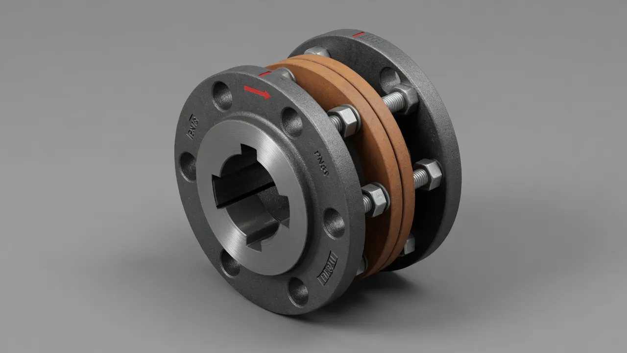
For applications above 5,000 Nm design torque or with service factors above 3.0, the heavy-duty shaft coupling range with ductile iron or alloy steel hubs is the appropriate product family ¡ª standard cast iron hubs at these torque levels are approaching their structural limits and are not recommended for cyclic shock loading.
Frequently Asked Questions
Need Expert Coupling Advice?
Our engineering team in Condell Park NSW is ready to help ¡ª free of charge.