Description
What Is a Rigid Coupling — and When Should You Use One?
A rigid coupling is a mechanical device that joins two shaft ends into a single, torsionally stiff assembly with no capacity for angular, radial, or axial movement between them. Unlike flexible couplings — which deliberately incorporate an elastomeric or metallic element to absorb misalignment and dampen vibration — a rigid shaft coupling transmits every Newton-metre of applied torque directly and instantaneously, without deflection, play, or energy loss. That characteristic is both its defining strength and the condition it places on the engineer: the connected shafts must be in precise coaxial alignment before the coupling is fastened.
Ever Power Flange Couplings Australia Ltd. supplies a comprehensive range of rigid flange couplings from our Sydney, NSW facility — covering standard flanged disc types, muff (sleeve) types, and split-muff configurations to suit everything from light-duty precision drives through to heavy industrial shaft transmission. Our stock spans cast iron models for general manufacturing and carbon steel grades for higher-torque applications, with aluminium alloy variants available where low rotational inertia is the primary requirement.
The three classical types of rigid coupling — muff coupling, split-muff coupling, and flange coupling — each suit different installation constraints. Of these, the flanged disc type is by far the most widely specified across NSW and Australian industry, offering the best combination of torque capacity, alignment precision, and ease of field inspection. This page covers the full range, with particular depth on the cast iron flange coupling and steel variants that form the core of our Sydney warehouse stock.
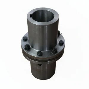
Cast iron rigid flange coupling — Ever Power Flange Couplings Australia Ltd., 27 Harley Crescent, Condell Park NSW 2200
Three Main Types of Rigid Coupling
While all rigid couplings share the same zero-backlash torque transmission principle, they differ meaningfully in construction, assembly method, and the type of shaft end they accommodate. Understanding these differences is the starting point for any selection decision. Our Sydney technical team can advise on the best type for your specific application — the brief guide below covers the main categories we stock and supply.
Flange Coupling (Disc Flange Type)
The most widely used form of rigid shaft coupling in Australian industry. Two flanged disc halves are keyed onto their respective shafts and bolted face-to-face. The bolt pattern carries the transmitted torque, and bolts may be reamed-hole (interference fit) for maximum precision or clearance-hole for easier disassembly. This type offers the highest torque density of all rigid coupling designs and the clearest path to precision alignment verification during installation. It is the standard choice for pump drives, gearbox connections, and power generation shaft trains across NSW manufacturing and mining sectors.
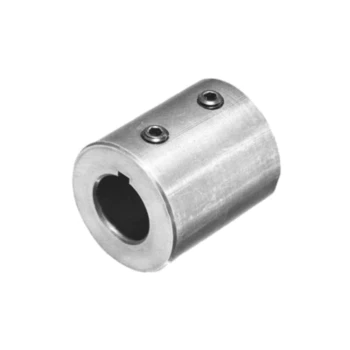
Muff Coupling (Sleeve Coupling)
A hollow cylindrical sleeve that fits over the two shaft ends, transmitting torque through keys on each shaft. The muff coupling has the smallest external diameter of all rigid types, making it well-suited for confined machine envelopes where the flanged disc type would be too bulky. It is, however, more demanding to disassemble — the driver or driven machine must be moved axially to withdraw the sleeve — so it is best reserved for installations where maintenance access is infrequent. Standard material is cast iron for medium-duty applications; carbon steel is specified for higher torque requirements.
Split-Muff Coupling (Clamp Coupling)
A two-piece sleeve design that splits horizontally along its length, clamped together with bolts. Because the sleeve halves can be removed radially without moving either machine, the split-muff type dramatically simplifies maintenance on long shaft systems where axial movement is impractical. It transmits torque via both key engagement and frictional clamping between the sleeve bore and shaft surface. This design is frequently chosen for long conveyor and pump shaft systems in NSW mining and quarrying operations where regular maintenance access is a priority.
Rigid Flange Coupling — Specifications & Parameters
The table below shows representative dimensional and performance parameters for our standard cast iron flange coupling range. All sizes conform to GB/T 5843 standard tolerances. Shaft bore (d) is machined to H7 tolerance as standard, and the keyway slot to h9. Carbon steel variants of the same dimensional envelope are available for higher-torque applications — nominal torque ratings for steel grades run approximately 25–40% above the cast iron figures shown. Stainless steel is available for corrosive environments; contact our Sydney team for pricing and lead time.
| Model | Nominal Torque (N·m) | Max Speed (rpm) | Bore d (mm) | Outer Dia. D (mm) | Length L (mm) | Material |
|---|---|---|---|---|---|---|
| GY1 | 16 | 6300 | 12–16 | 63 | 38 | HT200 |
| GY2 | 40 | 5600 | 14–20 | 80 | 44 | HT200 |
| GY3 | 100 | 4500 | 18–25 | 100 | 52 | HT200 |
| GY4 | 200 | 4000 | 22–32 | 120 | 62 | HT200 / 45# |
| GY5 | 400 | 3550 | 28–40 | 150 | 72 | 45# |
| GY6 | 800 | 3000 | 36–50 | 190 | 88 | 45# |
| GY7 | 1600 | 2500 | 45–63 | 240 | 104 | 45# |
| GY8 | 3150 | 2240 | 56–80 | 300 | 116 | 45# |
HT200 = Grey cast iron. 45# = Medium-carbon steel. Custom bore sizes, stainless steel, and aluminium alloy variants available on request. Contact our Sydney team for non-standard specifications.
Key Performance Features of Our Rigid Shaft Coupling Range
Every rigid flange coupling supplied by Ever Power Australia is selected and quality-checked against the following performance criteria. These are not marketing claims — they are the engineering properties that determine whether a rigid shaft coupling performs reliably in a real industrial environment over the long term. Understanding them helps you specify the correct grade and material for your application.
Torsional Rigidity & Zero Backlash
The rigid coupling transmits torque without any rotational play between driver and driven shafts — even under reverse loading or dynamic torque fluctuations. This makes it indispensable for servo-driven axes, test bench applications, and precision machining drives where positioning repeatability is the primary design criterion.
Lightweight with Ultra-Low Inertia
Compared to gear couplings of equivalent torque rating, the flanged disc rigid coupling offers a significantly lower rotational inertia due to its thin-web flange geometry. For drive systems with frequent start-stop cycles or rapid speed changes, this reduction in reflected inertia at the motor shaft directly reduces energy consumption and motor thermal load.
Maintenance-Free Operation
With no elastomeric elements to degrade, no lubricant to replenish, and no wearing surfaces under normal aligned operation, the rigid coupling has one of the lowest total lifecycle costs of any shaft connection method. Periodic bolt retorque checks — typically at 500-hour or annual intervals — are the only scheduled maintenance action required.
Oil & Corrosion Resistance
Cast iron and carbon steel variants are supplied with a standard primer coating and are compatible with mineral oils and most industrial lubricants. Stainless steel grades in our custom range offer genuine corrosion resistance for marine, food processing, and chemical plant environments — suitable where continuous moisture exposure or washdown routines would degrade painted cast iron units.
Multiple Fastening Configurations
Our flange-type rigid couplings accommodate three bolt configurations: full reamed-hole (all bolts interference fit for maximum torque without slipping), half-reamed (alternating bolt types balancing precision and serviceability), and standard clearance-hole for applications where ease of disassembly outweighs maximum torque density. Configuration is specified at order time.
Flexible Bore & Keyway Options
All units are available with different bore diameters at each end of the coupling — a common requirement when connecting a motor shaft of one diameter to a gearbox or pump shaft of a different diameter. Standard keyway is machined to h9 tolerance; double keyway, imperial keyway, and taper bore options are available from our Sydney custom machining service.
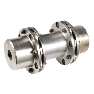
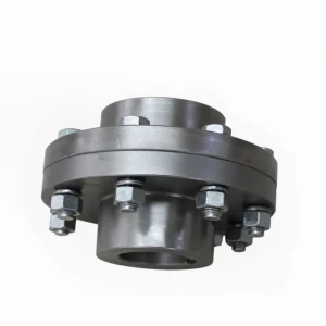
Cast iron and steel rigid flange coupling range — Ever Power Flange Couplings Australia, Sydney NSW
Advantages and Limitations — An Honest Engineering Assessment
Specifying any coupling type correctly begins with an objective understanding of its strengths and constraints. The rigid flange coupling performs exceptionally in the right conditions — and performs poorly when those conditions are not met. Our Sydney technical team always recommends the coupling best suited to your actual application, even when that means steering you towards a flexible alternative. Here is the full picture.
✅ Advantages
Simple, low-cost construction. Fewer components than any flexible type; no elastomeric elements to source or replace.
High torque capacity for its size. The flanged design transmits large torques through a compact cross-section, enabling smaller shaft diameters and lighter drive trains.
Precise alignment indication. Any misalignment during operation manifests immediately as bearing load and vibration — making faults detectable early through standard condition monitoring.
Suitable for high-speed drives. GY1–GY3 sizes are rated to 6,300 rpm — significantly higher than most elastomeric coupling types at equivalent bore diameters.
Long service life under aligned conditions. With no wearing elements and no fatigue-prone elastomers, a correctly installed rigid coupling routinely outlasts the bearing service intervals of the machines it connects.
⚠️ Limitations to Consider
Demands precision shaft alignment. Angular misalignment above 0.05 mm/100 mm or radial offset above 0.05 mm will transfer load directly to bearings and seals — reducing machine life progressively.
No vibration isolation. All torsional impulses, resonances, and shock loads pass through the coupling without attenuation. For reciprocating engine or compressor drives, a flexible coupling is usually the better choice.
No misalignment compensation. Thermal growth differences between driver and driven machines must be accounted for at the design stage — a rigid coupling cannot absorb them during operation.
Flange-type requires axial access for removal. Standard flanged disc types are removed axially; split-muff types avoid this constraint where maintenance access is limited.
Not sure which coupling type suits your application? Our Sydney engineering team can assess your shaft system parameters — speed, torque, alignment capability, and vibration environment — and recommend the most cost-effective solution from our full range of rigid and flexible couplings.
Rigid flange coupling in production — showing the flanged connection interface on an industrial power transmission shaft
Industrial Applications Served from Sydney, NSW
Rigid shaft couplings are the backbone of precision-aligned shaft systems across every major industrial sector in Australia. The applications below represent the core demand base that Ever Power supports from our Condell Park warehouse — where stock is maintained across the full standard range for rapid dispatch throughout New South Wales and interstate.
⚒ Mining & Quarrying
Ball mill and SAG mill shaft connections, crusher head drives, screen vibrator shafts, and primary conveyor drives across NSW open-cut and underground operations. The rigid coupling’s zero-backlash performance is particularly valued in mill drives, where any rotational play would amplify grinding media impact loads on gearbox teeth and bearings.
⚡ Power Generation & Utilities
Generator set shaft couplings, turbine-to-gearbox connections, and cooling water pump drives in both baseload and standby power plant. The rigid coupling’s high speed rating and low inertia make it the standard choice for synchronous generator direct-drive configurations common in Australian diesel and gas standby sets.
🏗 Heavy Manufacturing & Fabrication
Rolling mill stands, hydraulic press drives, crane gearbox outputs, and lathe headstock connections in NSW steel mills and heavy fabrication shops. The cast iron flange coupling is the standard choice for these applications where torque density and alignment precision take priority over vibration attenuation.
🔬 Precision Machining & CNC
CNC machine tool spindle drives, grinding machine heads, coordinate measuring machine drives, and test bed dynamometer connections all demand the zero-backlash torque path of a rigid coupling. In these applications, any angular play in the coupling translates directly into dimensional inaccuracy in the part being machined or measured.
🌊 Water & Waste Treatment
Pump station motor-to-pump shaft connections, aeration blower drives, and mixing equipment shafts in NSW water utilities. Where stainless steel flanges are specified for corrosion resistance, the rigid coupling maintains its dimensional stability and torque rating without the degradation that affects rubber-element flexible couplings in permanently wet environments.
🚢 Marine & Port Machinery
Winch gearbox outputs, mooring capstan drives, crane slew mechanisms, and container handling equipment at NSW port facilities. The split-muff rigid coupling type is particularly valued in marine machinery rooms where axial shaft movement for coupling removal is impractical within tight machinery space constraints.
Installation Requirements for Rigid Flange Couplings
The single most important determinant of rigid coupling performance is the quality of shaft alignment achieved at installation. Because the coupling provides no self-compensating movement, any angular or radial offset between the two shaft centrelines at the point of coupling imposes additional loads on the adjacent bearings and seals — loads that operate continuously at running speed and accumulate as fatigue damage. The five steps below represent current best practice for rigid flange coupling installation in Australian industrial applications.
Pre-Installation Inspection
Inspect the coupling bore and keyway for burrs, surface damage, or dimensional non-conformance before attempting shaft assembly. Verify the bore diameter with a calibrated bore gauge — it must fall within the specified H7 tolerance band. Inspect the mating shaft journal for roundness and surface finish; any ovality above 0.01 mm will compromise the running balance of the assembly.
Mounting the Coupling Halves
For interference-fit bores, use a hydraulic press or heat the coupling half in an oven to 80–100°C for thermal expansion mounting — never hammer directly on the flange face. Insert the key and verify full seating in both shaft and hub keyways without rotational play. Set the axial position of each coupling half to achieve the specified flange face gap before any fastening is commenced.
Precision Shaft Alignment
Measure angular and parallel (radial) misalignment using a laser alignment system or dial-indicator bracket. Target values: angular misalignment below 0.05 mm per 100 mm shaft length; parallel offset below 0.05 mm. For drives above 3,000 rpm, tighten these targets to 0.02 mm/100 mm and 0.02 mm respectively. Adjust the machine feet using calibrated shims until both targets are achieved simultaneously.
Bolt Installation & Torquing
Insert all flange bolts hand-tight before applying torque. Use a cross-pattern tightening sequence to achieve even flange face contact. Apply thread-locking compound to bolt threads where vibration is anticipated. Torque all bolts to the specification for the relevant coupling size and bolt grade using a calibrated torque wrench. Re-check alignment after tightening — bolt preload can induce small positional shifts in the machine feet.
Commission, Monitor & Retorque
Run the drive at reduced load initially and monitor vibration at the bearing housings and coupling area. A correctly installed rigid coupling should produce no perceptible vibration signature above the baseline for the motor and driven machine independently. After 100–200 operating hours, retorque the flange bolts to account for initial surface settling at the joint faces. Schedule bolt torque checks annually or at each planned maintenance shutdown thereafter.
Why Choose Ever Power as Your Rigid Coupling Supplier
For procurement engineers and maintenance managers across New South Wales, finding a local rigid flange coupling supplier with genuine technical depth — rather than a generalist distributor with a broad catalogue and shallow product knowledge — makes a practical difference when you need the right unit quickly, or when your shaft dimensions don’t match a standard stock item. Ever Power is that specialist.
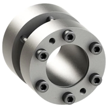
ISO 9001 certified production — rigid flange coupling range supplied by Ever Power Flange Couplings Australia Ltd.
Your Sydney Rigid Coupling Specialist — New South Wales
Sourcing rigid shaft couplings through a locally-stocked NSW supplier rather than ordering direct from overseas eliminates customs delays, reduces minimum order quantity pressures, and gives you access to a technical team who can provide phone support during Australian business hours. Ever Power Flange Couplings Australia Ltd. operates from Sydney’s south-western industrial district — positioned to serve the Hunter Valley, Illawarra, and greater Sydney manufacturing and mining base with same-day or next-day availability.
Australia Ltd.
Condell Park NSW 2200
New South Wales, Australia
Frequently Asked Questions
Technical and procurement questions answered by our Sydney engineering team.
Get a Quote or Technical Advice
Share your shaft diameter, torque requirement, and speed — our Sydney team will confirm the right rigid coupling size and a competitive price within one business day.
Ever Power Flange Couplings Australia Ltd. · 27 Harley Crescent, Condell Park NSW 2200 · [email protected] · flangecoupling.net