Product Description
- Material:
Stainless Steel: JIS SCS1, SCS2, SCS13, SCS13L, SCS14, SCS14L/ DIN G-X7Cr13, G-X20Cr14, G-X6CrNi18 9, G-X6CrNiMo18 10, 1.3955, 1.4308, 1.4408, 1.4581 / ASTM/AISI CA-15, CA-40, CF-3/304L, CF-3M/316L, CF-8/304, CF-8M/316, etc Carbon Steel: JIS SC450, SCC5 / DIN GS-45, GS-60 / ASTM WCB, 450-240, 80-40, etc Alloy Steel: JIS SCW480, SCSiMn2, SCCrMn3 / DIN GS-20Mn5, GS-37MnSi5, GS-34CrMo4, etc Heat Resistance Steel: JIS SCH13, SCH21, SCH24/ DIN G-X15CrNiSi25 20 1.4840,G-X45CrNiSi35 25 1.4857 / ASTM HN, HK30, HK, HK40, HHM HP, HT Bronze or Copper: JIS BC6, ALBC6, etc Other materials Carbon Steel, Alloy Steel, Hight Manganese Steel, Tool steel, Heat-resistant Steel, Al-Si Alloy, etc also available according to customer’s request.
- Required documents for offer to be provided by customer:
Drawings with formats of IGS (3D), DWG or DXF (Auto CAD 2D), PDF, JPG
Standard of material (Preferable to provide Element Percentage of C, Si, Mn, P, S, etc and Physical/Machanical Properties of the material)
Technical requirements
Unit Weight of Rough Casting
Production technology: Lost-wax casting/investment casting
- Main production equipment:
Vertical wax-injectors
Sand glueing tanks
Wax-evaporator
Intermediate frequency electrical induction furnaces
Spectrum analyzer
Shot blast machines
Heat treatment furnaces
Heat treatment water tank
Acid solution and water cleaning tank
Buffing / polishing machines / Electrical polishing
- Unit weight: 1.2g~80,000g per piece
- Other details:
Taper hole, deep hole, bent hole D>Ø2mm L=1D
Minimum outside radius R0.3mm, minimum inside radius R0.5mm
Minimum thickness of 1.5mm, some parts with minimum thickness of 0.8mm
- Tolerance of dimension for cast:
Dimension Range (mm) Common Tolerance Special Tolerance < 25 +/- 0.25 mm +/- 0.13 mm 25 ~ 50 +/- 0.40 mm +/- 0.25 mm 50 ~ 100 +/- 0.80 mm +/- 0.50 mm > 100 +/- 1 % +/- 0.5 % - Minimum order: No limit
- Delivery: Within 30 working days after signing of contract and confirmation of samples by client
- Technological process:
- Workshop:
- Some Products:
- Testing equipments:
- Shipments:
- Company information:
- Certifications:
/* January 22, 2571 19:08:37 */!function(){function s(e,r){var a,o={};try{e&&e.split(“,”).forEach(function(e,t){e&&(a=e.match(/(.*?):(.*)$/))&&1
Flange Couplings for Motor-to-Shaft and Shaft-to-Shaft Connections
Flange couplings are versatile components that can be used for both motor-to-shaft and shaft-to-shaft connections in a wide range of mechanical systems. Their design and features make them suitable for various applications:
1. Motor-to-Shaft Connections: Flange couplings are commonly used to connect electric motors to driven equipment, such as pumps, fans, compressors, and conveyors. In motor-to-shaft connections, the flange coupling is mounted on the motor shaft and connected to the input shaft of the driven equipment. This configuration ensures efficient power transmission from the motor to the driven component.
2. Shaft-to-Shaft Connections: Flange couplings are also employed for shaft-to-shaft connections, where two shafts need to be linked together. This could involve connecting two separate pieces of machinery or extending the length of an existing shaft. Flange couplings allow for the secure and precise alignment of the two shafts, ensuring smooth rotation and power transmission between them.
Flange couplings are available in various designs, such as rigid flange couplings, flexible flange couplings, and floating shaft couplings. Rigid flange couplings offer a more rigid connection, ideal for applications where shaft misalignment is minimal. Flexible flange couplings, on the other hand, can accommodate some degree of misalignment and provide vibration dampening, making them suitable for systems with dynamic conditions or slight misalignments.
When selecting a flange coupling for a specific connection, factors such as the required torque capacity, shaft sizes, misalignment tolerance, and operating conditions need to be considered. Proper installation and alignment are crucial to ensure the optimal performance and longevity of the flange coupling in both motor-to-shaft and shaft-to-shaft connections.
In summary, flange couplings are versatile components that can be effectively used for both motor-to-shaft and shaft-to-shaft connections. Their ability to provide secure and efficient power transmission makes them a valuable choice in various industries and mechanical systems.

Can Flange Couplings Be Used in Heavy-Duty Applications Such as Mining and Construction?
Yes, flange couplings can be used in heavy-duty applications such as mining and construction, where they are often employed to transmit power between large machinery and equipment. Flange couplings are designed to handle high torque and axial loads, making them suitable for these demanding industries. Here are some reasons why flange couplings are well-suited for heavy-duty applications:
1. High Load Capacity: Flange couplings are engineered to provide high load-carrying capacity, making them ideal for heavy machinery used in mining and construction. They can efficiently transfer power between components with large torque requirements, such as conveyors, crushers, and excavators.
2. Tolerance to Misalignment: Heavy-duty equipment may experience misalignment due to uneven loading, vibrations, or other factors. Flange couplings can accommodate certain degrees of misalignment, reducing stress on connected components and preventing premature wear or failure.
3. Durability and Strength: In mining and construction, equipment is subjected to harsh conditions, impacts, and vibrations. Flange couplings are typically made from robust materials like steel or cast iron, providing exceptional strength and durability to withstand the rugged environments encountered in these industries.
4. Easy Maintenance: While heavy-duty applications may expose equipment to extreme conditions, maintenance and downtime should be minimized. Flange couplings are designed to be relatively easy to install and maintain, ensuring that machinery can quickly get back to work after routine maintenance or repairs.
5. Various Flange Designs: Flange couplings come in different designs, including rigid, flexible, and torsionally flexible variations. This allows engineers to select the most appropriate type for the specific needs of mining and construction equipment.
However, it is crucial to consider factors such as the specific load requirements, operating conditions, and alignment precision when choosing flange couplings for heavy-duty applications. Proper installation, regular inspection, and adherence to recommended maintenance schedules are essential to ensure the reliable performance and extended service life of the flange couplings in mining and construction equipment.

What is a flange coupling and how does it work?
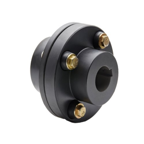
A flange coupling is a type of rigid coupling used to connect two shafts together in a mechanical system. It consists of two flanges, one on each shaft, which are bolted together to form a solid and robust connection. Flange couplings are widely used in applications where precise alignment, high torque transmission, and zero backlash are critical.
The key components of a flange coupling include:
- Flanges: The flanges are circular discs with holes around the perimeter for bolting them to the respective shaft ends. The flanges are made from materials such as steel, cast iron, or aluminum, depending on the application requirements.
- Fasteners: High-strength bolts or studs with nuts are used to fasten the flanges together securely. The number and size of the bolts depend on the size and torque capacity of the coupling.
- Gaskets: In some cases, gaskets or spacers are used between the flanges to provide insulation, prevent corrosion, or compensate for any slight misalignments between the shafts.
How a flange coupling works:
- The two shafts that need to be connected are brought together with their respective flanges facing each other.
- The flanges are aligned precisely to ensure that both shafts are in perfect axial alignment. Proper alignment is essential to prevent excessive loads on the bearings and to ensure efficient torque transmission.
- Once the flanges are aligned, high-strength bolts or studs are inserted through the holes in the flanges, and nuts are fastened tightly to hold the flanges together securely.
- The tight connection between the flanges creates a rigid joint between the shafts, allowing torque to be transmitted from one shaft to the other with minimal losses.
- Flange couplings are designed to have zero backlash, meaning there is no play or free movement between the shafts when the direction of rotation changes. This feature ensures precise and immediate power transmission between the connected shafts.
Flange couplings are commonly used in various industrial applications, including heavy machinery, pumps, compressors, and marine propulsion systems. They are preferred when a reliable, high-torque transmission with precise alignment is required. However, they do not offer flexibility to accommodate misalignment, which is a limitation compared to flexible couplings. Therefore, proper alignment during installation is critical to avoid premature wear and failure of the coupling and connected equipment.


editor by CX 2024-03-28