
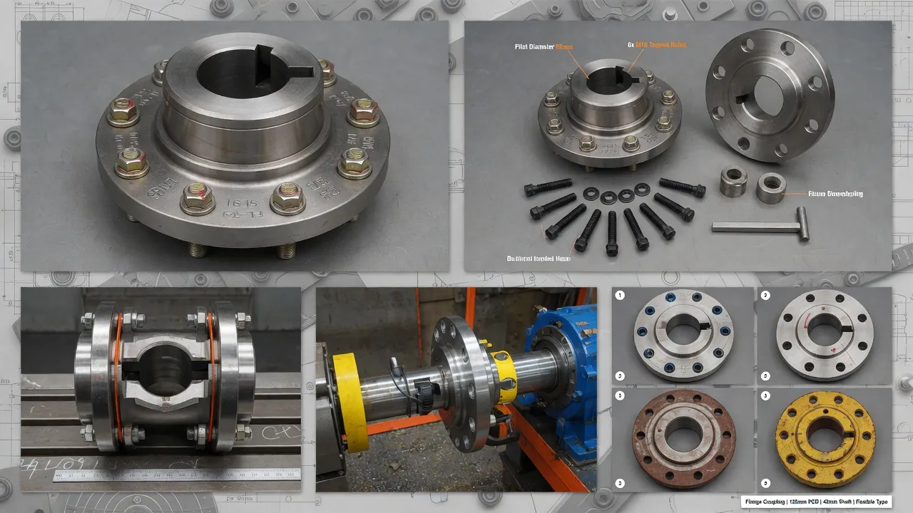
Why Coupling Vibration Is Never a Minor Issue
When a rotating drivetrain develops vibration, the coupling is not always the primary culprit — but it is always part of the transmission path. Even if the vibration originates in the motor or the driven load, the shaft coupling either absorbs it, amplifies it, or passes it through unchanged, depending on its design and condition. This is why understanding vibration in a coupling context requires looking at the entire drivetrain, not just the coupling itself.
The consequences of sustained coupling vibration are well documented in rotating machinery failure statistics. Increased radial bearing loads reduce L10 bearing life in proportion to the cube of the load increase — a doubling of radial load cuts bearing life to one-eighth. Pump mechanical seals, designed to operate with shaft deflection below 0.05 mm, fail prematurely when vibration-induced deflection exceeds that threshold. Structural fatigue in pipework connected to a vibrating pump can produce cracks and leaks within months. In short, a vibrating flange coupling that is not investigated promptly will produce a cascade of secondary failures that cost far more to rectify than the coupling replacement itself.
The Seven Root Causes of Shaft Coupling Vibration
Every vibrating coupling investigation eventually traces back to one or more of the following root causes. Understanding the mechanical signature of each makes field diagnosis far more reliable than guesswork.
How to Diagnose Coupling Vibration: A Practical Field Approach
Vibration diagnosis does not always require sophisticated instrumentation. A systematic field approach — combining visual inspection, vibration frequency identification, and response to operating variables — will correctly identify the root cause in the majority of cases encountered in Australian industrial plant.
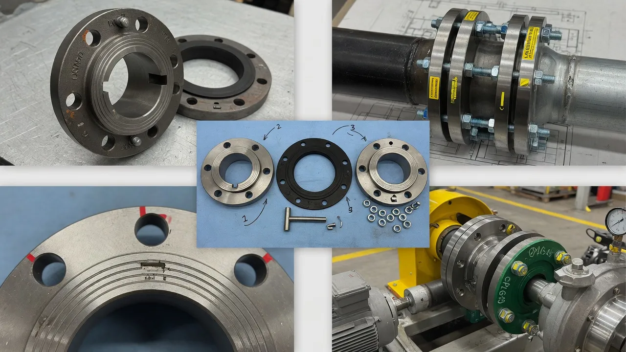
Step 1 — Visual and Tactile Inspection (Machine Stopped)
Before any measurements, shut down the machine, lock out and tag out, and inspect the coupling physically. Check for rubber debris or dust inside the coupling guard (spider wear), any axial or radial play when you attempt to rock the hubs by hand (loose hub fit or worn spider), missing or sheared coupling bolts, surface cracks on hub flanges, and evidence of fretting corrosion at the keyway. Any of these findings narrows the diagnosis significantly before instrumentation is involved.
Step 2 — Identify the Dominant Vibration Frequency
With the machine running safely, a handheld vibration meter with spectrum capability will identify the dominant frequency component. A peak at exactly 1× RPM typically points to imbalance or a loose hub. A dominant 2× RPM component points to misalignment (especially angular). Sub-synchronous frequencies suggest torsional issues. If the coupling guard prevents direct measurement at the coupling, take readings at the motor bearing housing and the driven-machine bearing housing — the pattern difference between the two measurement points helps locate the vibration source.
Step 3 — Test Response to Load and Speed Changes
Vary the operating speed if a variable speed drive is available, and note whether the vibration amplitude tracks proportionally with speed squared (imbalance behaviour), increases at specific speeds (resonance), or responds primarily to load changes (torsional or coupling stiffness issues). Coupling misalignment vibration typically increases with operating temperature as thermal growth shifts shaft positions — a vibration that is low at cold start but increases after 30 minutes of running is a strong indicator of thermally-induced misalignment.
Step 4 — Perform a Laser Shaft Alignment Check
Regardless of what the vibration spectrum suggests, a laser shaft alignment check should be standard practice in any coupling vibration investigation. It is quick, conclusive, and inexpensive relative to the cost of continued operation with misalignment. Record both cold and hot alignment readings where possible. Misalignment found at this stage resolves the vast majority of coupling vibration cases in field experience — in our estimation, misalignment is the confirmed root cause in well over half of all coupling vibration investigations handled by our New South Wales service team.
Does Coupling Type Affect Vibration Behaviour?
Coupling type has a direct and significant effect on drivetrain vibration. Selecting the right coupling for an application is not just about torque capacity and bore diameter — it is also about controlling the vibration behaviour of the entire drivetrain system throughout its service life.
(Elastomeric Spider Type)
Provides inherent vibration damping through the elastomeric element. Accommodates misalignment-induced dynamic forces before they reach the bearings. Vibration increases progressively as the spider ages — giving early warning of wear before catastrophic failure. Best overall choice for general industrial pump and compressor drives.
(No Flex Element)
Transmits all vibration without attenuation. A perfectly aligned rigid coupling is quiet; one with even minor misalignment will generate sustained bearing loads. Produces no early warning — the first sign of trouble is often a bearing failure rather than progressive vibration increase. Only suitable where alignment can be guaranteed under all operating conditions.
(Metallic Flex Element)
Low damping but high torsional stiffness. Accommodates misalignment through controlled metallic flexure rather than elastomeric deformation. Less vibration damping than a spider-type flexible coupling, but virtually maintenance-free and capable of very high speed operation. Vibration behaviour remains consistent throughout service life with no wear degradation in the flex element.
For most pump and compressor applications in Australian industry, an F-type elastomeric flexible flange coupling provides the best combination of vibration control, misalignment tolerance, and maintenance simplicity. The elastomeric tyre element absorbs both angular misalignment and parallel misalignment while providing meaningful damping of torsional and radial vibration — a combination that no metallic coupling can match without significantly more complex design.
Why Does Misalignment Cause Coupling Vibration?
Shaft misalignment is the most misunderstood vibration source in rotating machinery, largely because the connection between misalignment and vibration is mechanical rather than immediately intuitive. When two shafts are not co-linear, the coupling connecting them must continuously deform and recover as it rotates — once per revolution for angular misalignment, twice per revolution for parallel misalignment. Each deformation cycle generates a restoring force transmitted through the coupling hubs to the motor and driven-machine shafts. These cyclic forces produce the characteristic vibration frequencies, and also impose sustained radial loads on the bearings at both ends of the coupling.
The practical implication is that coupling misalignment does not just vibrate the coupling — it loads the entire bearing system continuously at running frequency, reducing bearing life dramatically. Published bearing life equations show that a 20% increase in radial bearing load reduces L10 life by approximately 49%. In practice, this means a motor bearing rated for 40,000 hours at rated load may last only 20,000 hours or less with even modest sustained misalignment-induced radial loading. This damage mechanism operates silently until the bearing fails, which is why alignment checks — not vibration measurements alone — should be the routine maintenance tool for all coupled drivetrains.
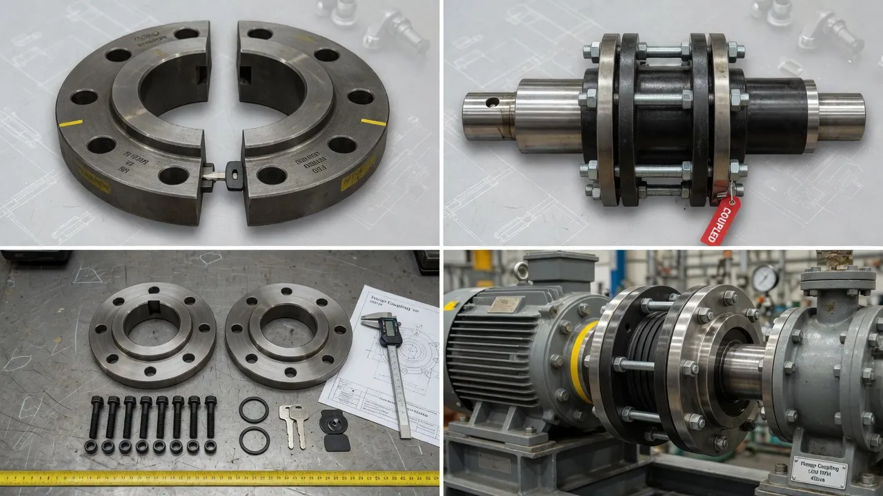
Why Does a Coupling Spider Wear Out and What Happens Next?
The elastomeric spider in a flexible coupling undergoes a predictable degradation sequence that every maintenance engineer should understand. Fresh polyurethane or rubber spider material is viscoelastic — it deforms under load and recovers elastically, dissipating energy as heat through hysteresis. This hysteretic behaviour is exactly what provides vibration damping. Over time, material fatigue, UV exposure, chemical contamination, heat cycling, and cumulative compression set progressively reduce the elastomer’s resilience. The spider becomes stiffer, less able to damp vibration, and eventually begins to fracture.
The vibration signature changes in a characteristic way as this happens. Early spider wear produces modest vibration increase at 1× RPM. As degradation accelerates, the vibration amplitude rises more steeply, and a broadband noise floor often increases. In the final degradation stage — when spider lobes begin chunking out — metal-to-metal contact between hub jaws produces high-amplitude impact vibration with frequency components across a wide spectrum. By this stage, hub jaw wear has typically begun, and the coupling itself requires replacement rather than just a spider change. The lesson is straightforward: replace spider elements on a scheduled basis before they reach the chunking stage, because the cost of a spider insert is a small fraction of the cost of a hub replacement.
How to Fix Shaft Coupling Vibration: Corrective Actions by Cause
Once the root cause has been identified, the corrective action is usually straightforward. The following table maps each cause to its correct fix and gives a realistic estimate of the improvement expected.
| Root Cause | Corrective Action | Expected Outcome |
|---|---|---|
| Shaft misalignment | Laser alignment — correct angular and parallel offset to within half the coupling’s rated tolerance | Immediate and significant vibration reduction |
| Worn spider element | Replace elastomeric spider insert with correct hardness grade for the application | Restores damping; vibration returns to baseline |
| Coupling imbalance | Clean coupling, inspect for uneven wear; rebalance assembly dynamically if necessary | 1× vibration component drops substantially |
| Loose hub or bolts | Re-torque to specification; inspect keyway and set screw condition; replace if worn | Eliminates knock and impact vibration |
| Wrong coupling type | Replace with correctly specified coupling; recalculate torque rating, misalignment tolerance, and torsional stiffness | Sustained vibration reduction throughout service life |
| Torsional resonance | Torsional analysis to identify the natural frequency; change coupling torsional stiffness or adjust drive speed to detune | Dramatic reduction in vibratory torque amplitude |
| External vibration source | Investigate and repair the source component (motor, pump, gearbox); coupling may need no action | Vibration eliminated at source; coupling undamaged |
Preventing Coupling Vibration: A Maintenance Programme That Works
The most effective approach to coupling vibration is a structured preventive maintenance programme that eliminates the conditions that allow vibration to develop in the first place. Based on the failure patterns we see most frequently across our Australian customer base, the following programme elements provide the highest return on maintenance investment for coupled drivetrains.
Even drivetrains with stable baseplates drift alignment over 12 months through thermal cycling, minor foundation movement, and equipment interchange. An annual laser alignment check — ideally performed during a planned shutdown — costs less than two hours of technician time and catches drift before it reaches the threshold that affects bearing life. Record all readings; a trend of increasing misalignment between annual checks is a leading indicator of baseplate or foundation problems that need structural attention.
Remove the coupling guard annually and inspect the elastomeric spider visually and manually. Feel for surface cracking and loss of resilience; look for rubber dust or debris. A spider showing early-stage cracking can often run safely until the next planned maintenance window — an advanced-stage spider should be replaced immediately. Keep one spare spider insert per coupling on the site shelf; the cost is trivial and it avoids the unplanned shutdown that a failed spider can cause if no spare is available.
Take and record a simple overall vibration reading (mm/s RMS) at the motor and driven-machine bearing housings every three months. Trending this value over time — rather than comparing it to an absolute alarm level — gives the earliest possible warning of developing problems. A 25% increase above baseline triggers an investigation; it does not necessarily trigger a shutdown. This simple quarterly check has consistently proved more effective than annual inspection alone in preventing unplanned machine failures in our customers’ plants.
Loose motor hold-down bolts allow the motor to shift under starting torque, progressively worsening shaft alignment and introducing vibration that compounds with every start-stop cycle. Check and re-torque hold-down bolts at each annual shutdown. Apply thread-locking compound to bolts where vibration-induced loosening is a recurring problem. Ensure that soft-foot — where one motor foot is slightly elevated from the baseplate — has been corrected before any final alignment tightening.
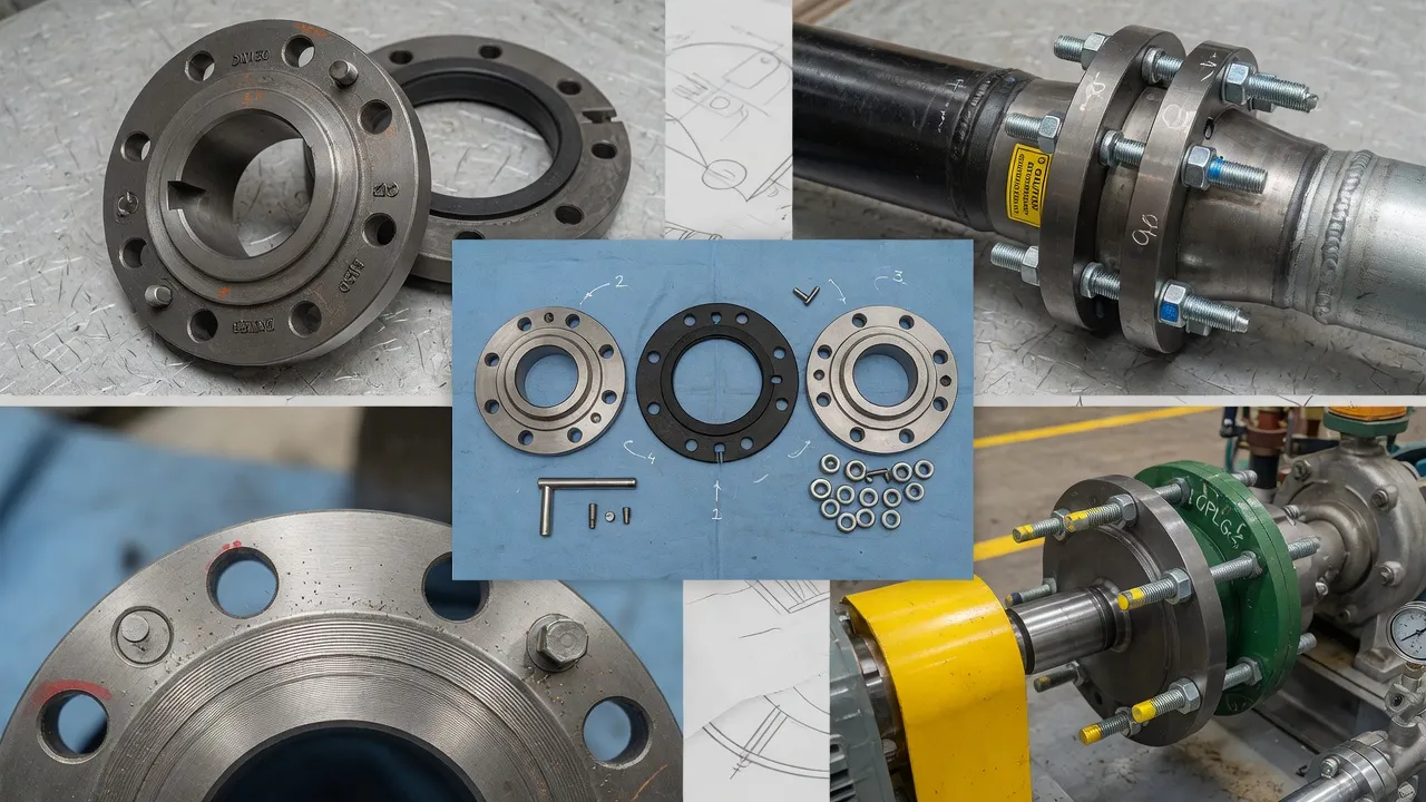
When to Replace the Coupling Entirely vs. Just the Spider
A common practical question from plant maintenance teams is whether a coupling showing vibration problems needs complete replacement, or whether a spider element change is sufficient. The decision depends on the condition of the hubs and the root cause of the vibration.
Replace the spider only — and retain the existing hubs — when: the spider is worn but the hub jaws show no scoring, cracking, or deformation; the hub bores show no signs of fretting corrosion or shaft slip; the coupling bolts and bolt holes show no wear or elongation; and the root cause of vibration was spider degradation alone with no misalignment contribution. In this scenario, a spider replacement restores the coupling to original performance at a fraction of the cost of full replacement.
Replace the complete coupling when: hub jaws show wear, scoring, or deformation from metal-to-metal contact with a failed spider; hub bores show fretting corrosion or enlargement indicating shaft slip; coupling bolts are sheared or bolt holes are worn; the coupling has been subjected to a confirmed overload event such as a shock load or hydraulic surge; or the root cause investigation has concluded that the original coupling was incorrectly specified for the application. For applications where rigid flange coupling hubs are concerned, a replacement cast iron and steel rigid shaft coupling provides the re-machined bore accuracy and dimensional precision that a worn-hub replacement cannot match.
Experiencing Coupling Vibration? Our Team Can Help.
Send us your vibration data and installation details — we’ll advise on root cause and the correct coupling solution, at no charge.
Frequently Asked Questions
27 Harley Crescent, Condell Park NSW 2201, New South Wales, Australia
+61 29708 3322 |
[email protected] |
Contact Us