Description
The NM coupling is a jaw-style flexible coupling built around an NBR nitrile butadiene rubber elastic element captured between two cast iron hubs with interlocking jaw profiles. The NBR compound delivers excellent resistance to mineral oil, grease, fuel splash, and many industrial chemicals while maintaining elastic recovery across an operating range from -40 °C to +100 °C. The NM range covers seven core sizes from NM 50 through NM 148 and is supplied as a direct dimensional cross-reference for Tsubaki NM, Dodge jaw, Lovejoy jaw, and Mitsuboshi NM couplings.
NM Coupling Specifications and Torque Ratings
The NM range spans the light-duty through heavy-duty industrial drive torque envelope, from 4 N·m at the smallest NM 50 size up to 560 N·m at the largest NM 148 size. Each size is offered with the widest stock bore and keyway combinations in its size class — metric H7 bores with DIN 6885 keyways, imperial fractional bores with parallel imperial keyways, spline profiles, hex bores, and set-screw blanks are all available from stock. The complete dimensional and torque envelope is summarised in the specification table below.
| Model | Nominal Torque (N·m) | Max Speed (rpm) | Bore Range (mm) | Outer Diameter (mm) | Overall Length (mm) |
|---|---|---|---|---|---|
| NM 50 | 4 | 6300 | 8 – 22 | 50 | 35 |
| NM 67 | 10 | 5600 | 12 – 32 | 67 | 45 |
| NM 82 | 25 | 5000 | 18 – 40 | 82 | 54 |
| NM 97 | 56 | 4500 | 22 – 50 | 97 | 65 |
| NM 112 | 125 | 4000 | 30 – 60 | 112 | 75 |
| NM 128 | 250 | 3550 | 38 – 65 | 128 | 84 |
| NM 148 | 560 | 3150 | 45 – 75 | 148 | 96 |
Operating temperature range across the full NM range is -40 °C to +100 °C with the standard NBR compound. Higher-temperature variants — HNBR for sustained operation up to +130 °C and Hytrel polyester elastomer for intermittent exposure up to +120 °C with substantially higher torque density — are available on request for chemical, petrochemical, and elevated-temperature drive applications where the standard NBR ring would degrade prematurely.
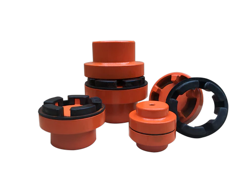
NM Coupling – jaw-style flexible coupling with NBR nitrile butadiene rubber elastic element. NM 50 through NM 148. Ever Power Flange Couplings Australia Ltd.
How the NM Coupling Transmits Torque
Two cast iron hubs face each other across a small axial gap. Each hub carries an array of solid jaws — typically six on the smaller sizes and eight on the larger sizes — projecting axially toward the opposite hub. The jaws of one hub interlock with the jaws of the opposite hub in a clocked arrangement so that each jaw on the input hub sits between two jaws on the output hub. The NBR rubber element is moulded as a single ring with axial fingers that fill every gap between the interlocking jaws.
When torque is applied to the input hub, each input-hub jaw presses against an NBR finger, which in turn presses against the adjacent output-hub jaw. The rubber finger is captured between two jaws on every flank and transmits torque through compression rather than shear. Because each finger of the elastic element is shared between adjacent jaws, the total torque is divided across all engagement faces simultaneously — six engagement points on six-jaw sizes, eight on eight-jaw sizes — and the rubber compound operates well below its compressive failure stress at the rated torque.
Misalignment Accommodation
The same NBR element that transmits torque also absorbs misalignment between the two shafts. Angular misalignment up to 1.0° is accommodated by differential compression of the rubber fingers across the face of the coupling — fingers on the high side compress more, fingers on the low side compress less. Parallel offset up to 0.4 mm and axial movement up to 1.4 mm are accommodated by the elastic envelope of the rubber compound. The same compound also provides high internal hysteresis damping, absorbing torsional vibration from the driver and reducing shock loading transmitted to the driven shaft.
Construction and NBR Material Specification
Both hubs are produced from grey cast iron grade GG-25 or ductile iron grade GGG-40 depending on the size and torque class. Hubs are precision machined on the bore, keyway, and jaw faces to dimensional tolerances appropriate to the engagement geometry — bore tolerance H7, keyway tolerance JS9, jaw face perpendicularity within 0.05 mm to the bore axis. Hub clamp screws, set screws, and shaft-end retention features are supplied to customer specification on every order.
The elastic ring is compression-moulded from NBR rubber compound with a Shore A hardness in the range of 80 to 92, depending on size and application. The NBR compound carries an oil swell index below 5 percent in IRM 902 reference oil at 70 °C for 168 hours — a key specification for any elastomeric coupling exposed to lubricant splash from gearboxes, hydraulic packs, or air compressors. Tensile strength of the cured rubber exceeds 18 MPa and elongation at break exceeds 250 percent — both substantially higher than equivalent natural rubber compounds used in lower-cost jaw couplings.
Engineering Features at a Glance
🛡️ Oil and Chemical Resistance
NBR rubber compound resists mineral oil, grease, fuel, and many industrial chemicals — suitable for use adjacent to lubricated gearboxes, hydraulic packs, and air compressors without degradation.
🌡️ Wide Temperature Range
Standard NBR compound rated -40 °C to +100 °C continuous service. HNBR upgrade extends continuous operation to +130 °C for elevated-temperature drive lines.
⚙️ Widest Stock Bore Range
Metric H7, imperial fractional, spline, hex, and set-screw blank bore configurations all kept in stock — typically the broadest stock bore matrix in the jaw coupling category.
🔇 Low-Noise Operation
Compressive jaw engagement through the rubber element produces measurably lower running noise than metal-to-metal jaw couplings, particularly at high speed.
🧰 No Lubrication Required
The NBR element is the working component — no grease, oil, or service lubricant is required for the life of the coupling. Service intervals are inspection-only.
🔁 Drop-In OEM Replacement
Dimensionally and torque-rated as a direct cross-reference for Tsubaki NM, Dodge jaw, Lovejoy L and AL series, and Mitsuboshi NM jaw couplings.
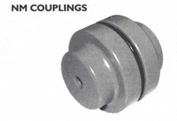
NM Coupling assembly showing interlocking cast iron jaw hubs and the NBR rubber element captured between them.
Application Fields and Drive Configurations
The NM range is specified across light, medium, and heavy-duty motor drive applications in process plant, manufacturing, and infrastructure equipment. The combination of compact envelope, low inertia, oil and chemical resistance, and broad bore range makes the NM an appropriate motor coupling selection for the majority of electric-motor-driven pump, fan, compressor, gearbox, and conveyor packages produced for the Australian and regional industrial market.
Typical Drive Packages
Centrifugal pumps and gear pumps driven by IEC and NEMA frame motors — particularly chemical transfer, dosing, lubrication, and coolant pumps where mineral oil or hydrocarbon splash from leakage or piping joints is normal. Gearbox input shafts on close-coupled motor-gearbox packages, where the NM provides torsional isolation between the motor and the gearbox bearing system. Air compressor V-belt drives and direct drives, where the NM compensates for installation misalignment between the motor and the compressor crankshaft.
Process Industry and Special Applications
Chemical process plant blowers, mixers, agitators, and conveyors exposed to occasional solvent splash or vapour environments — the NBR compound resists short-duration exposure to many polar and non-polar solvents that would attack natural rubber within hours. Food processing equipment driven by stainless steel motors, where the FDA-grade NBR variant is specified for incidental food contact zones. Agricultural equipment power take-offs and PTO drive packages exposed to dust, mud, fertiliser, and pesticide environments.
Selecting the Correct NM Size for Your Drive
Coupling selection follows the standard service-factor method. Multiply the nominal motor torque by the service factor for the driven equipment class — 1.0 for steady continuous duty, 1.5 for moderate shock loads such as centrifugal pumps and fans, 2.0 to 2.5 for shock loads such as reciprocating compressors and crushers, 2.5 to 3.5 for severe shock applications. Compare the resulting design torque to the published nominal torque for each NM size and select the smallest size whose nominal torque equals or exceeds the design torque.
Verify that both shaft diameters fall within the bore range of the selected size and that the maximum operating speed does not exceed the maximum speed for the selected size. For elevated ambient temperature above +80 °C, derate the published torque by 10 percent per 10 °C of additional temperature above the +80 °C reference. The engineering team at Ever Power Flange Couplings Australia Ltd. provides full selection support, OEM cross-reference checking, and shaft-end engineering review on every quotation — contact details are listed at the end of this page.
Request NM Coupling Quote and Selection Support
Installation Workflow
Installation of the NM coupling is straightforward and does not require specialist tools beyond a torque wrench, a feeler gauge, and a straight edge. The four steps below cover the standard fitting sequence for an NM coupling onto two shafts that have been previously aligned to within 0.5 mm parallel and 0.5° angular by laser or dial gauge.
Step 1 — Hub Fitting
Fit each hub onto its respective shaft to the published axial position. Use a soft-faced mallet on the hub face if the bore is sized for a slip fit, or use an induction heater set to 90 °C for shrink-fit configurations. Tighten the key clamp screw or set screw to the published torque after the hub has cooled to ambient.
Step 2 — Axial Gap Check
Move both shafts axially until the gap between the two hub faces matches the published assembly dimension for the size selected — typically 2 mm for NM 50 through NM 97, 3 mm for NM 112 and NM 128, 4 mm for NM 148. Verify the gap with a feeler gauge at four points around the circumference.
Step 3 — Element Installation
Slide the NBR rubber element axially into the gap between the two hub faces. The jaws of both hubs must engage all rubber fingers simultaneously — if any finger is bent or skewed, withdraw the element, realign, and re-insert. Do not force the element with a hammer or lever — damaged rubber fingers will reduce torque capacity and shorten service life.
Step 4 — Final Alignment Verification
With the rubber element installed, rotate the shafts by hand through one full revolution and verify smooth engagement at every angular position. Measure parallel and angular misalignment at four equally spaced angular positions using a dial gauge or laser tool, and confirm the readings are within the published misalignment limits for the size selected.
Maintenance and Element Replacement
The NM coupling requires no scheduled maintenance beyond visual inspection of the rubber element at the same interval as the bearings of the connected equipment — typically every six months for continuous-duty installations and every twelve months for intermittent-duty installations. Inspection involves removing one hub guard, illuminating the rubber element, and checking for surface cracks, abrasion against the hub, swelling from chemical attack, or hardening from heat exposure. Any of these conditions indicates the element should be replaced before failure.
Element replacement is a fifteen-minute task on most installations and does not require any disassembly of the connected equipment. Remove the hub guard, slide the old element axially out of the jaw engagement, slide a new element into position, and replace the guard. The cast iron hubs themselves typically operate for the life of the connected equipment without replacement — a properly sized and installed NM coupling will see five to ten rubber element changes before any hub-side service is required.
Why Choose Ever Power Australia
Ever Power Flange Couplings Australia Ltd. has supplied flexible coupling products to the Australian industrial, mining, agricultural, and process industries for more than two decades. Every NM coupling shipped from our Condell Park facility is dimensionally cross-checked against the Tsubaki, Dodge, Lovejoy, and Mitsuboshi reference catalogues, individually inspected, and supplied with a full material certificate covering both the cast iron hubs and the NBR rubber element. Bore machining, keyway cutting, and shaft-end engineering are performed in-house on every order — typical lead time on stock bore configurations is one to three business days from the Sydney warehouse, with same-day collection available for Sydney metropolitan customers.
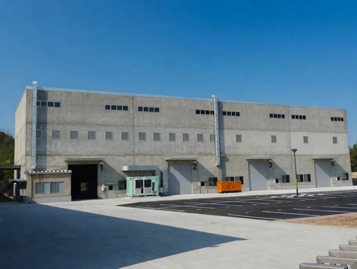
Ever Power manufacturing facility — ISO 9001 certified, 12,000 m², 108 dedicated coupling machines, 20+ years of production experience.
Every order placed with our Sydney team is backed by full material traceability, dimensional inspection certificates on request, and direct access to the engineers who specified, machined, and packed your coupling. We do not subcontract technical support — when you phone +61 2 9708 3322 during NSW business hours, you reach the people who actually know the product.
Frequently Asked Questions
Quick answers from our Sydney technical team. Contact us for application-specific guidance.
1. Is the NM coupling interchangeable with Tsubaki NM and Lovejoy jaw couplings? +
2. What is the operating temperature range of the NBR element? +
3. Can the NM coupling be used in oil-splash environments? +
4. What lead time applies to non-stock bore configurations? +
5. How often does the NBR element need to be replaced? +
Request a Quote — Sydney NSW Stock
Tell us your motor power, shaft diameter, and operating environment. Our New South Wales coupling team confirms availability and pricing within one business day, with same-day dispatch on standard sizes from Condell Park.
Ever Power Flange Couplings Australia Ltd. · 27 Harley Crescent, Condell Park NSW 2200 · [email protected]