Product Description
| Basic Info. of Our Customized CNC Machining Parts | |
| Quotation | According To Your Drawings or Samples. (Size, Material, Thickness, Processing Content And Required Technology, etc.) |
| Tolerance | +/-0.005 – 0.01mm (Customizable) |
| Surface Roughness | Ra0.2 – Ra3.2 (Customizable) |
| Materials Available | Aluminum, Copper, Brass, Stainless Steel, Titanium, Iron, Plastic, Acrylic, PE, PVC, ABS, POM, PTFE etc. |
| Surface Treatment | Polishing, Surface Chamfering, Hardening and Tempering, Nickel plating, Chrome plating, zinc plating, Laser engraving, Sandblasting, Passivating, Clear Anodized, Color Anodized, Sandblast Anodized, Chemical Film, Brushing, etc. |
| Processing | Hot/Cold forging, Heat treatment, CNC Turning, Milling, Drilling and Tapping, Surface Treatment, Laser Cutting, Stamping, Die Casting, Injection Molding, etc. |
| Testing Equipment | Coordinate Measuring Machine (CMM) / Vernier Caliper/ / Automatic Height Gauge /Hardness Tester /Surface Roughness Teste/Run-out Instrument/Optical Projector, Micrometer/ Salt spray testing machine |
| Drawing Formats | PRO/E, Auto CAD, CHINAMFG Works , UG, CAD / CAM / CAE, PDF |
| Our Advantages | 1.) 24 hours online service & quickly quote and delivery. 2.) 100% quality inspection (with Quality Inspection Report) before delivery. All our products are manufactured under ISO 9001:2015. 3.) A strong, professional and reliable technical team with 16+ years of manufacturing experience. 4.) We have stable supply chain partners, including raw material suppliers, bearing suppliers, forging plants, surface treatment plants, etc. 5.) We can provide customized assembly services for those customers who have assembly needs. |
| Available Material | |
| Stainless Steel | SS201,SS301, SS303, SS304, SS316, SS416, etc. |
| Steel | mild steel, Carbon steel, 4140, 4340, Q235, Q345B, 20#, 45#, etc. |
| Brass | HPb63, HPb62, HPb61, HPb59, H59, H62, H68, H80, etc. |
| Copper | C11000, C12000,C12000, C36000 etc. |
| Aluminum | A380, AL2571, AL6061, Al6063, AL6082, AL7075, AL5052, etc. |
| Iron | A36, 45#, 1213, 12L14, 1215 etc. |
| Plastic | ABS, PC, PE, POM, Delrin, Nylon, PP, PEI, Peek etc. |
| Others | Various types of Titanium alloy, Rubber, Bronze, etc. |
| Available Surface Treatment | |
| Stainless Steel | Polishing, Passivating, Sandblasting, Laser engraving, etc. |
| Steel | Zinc plating, Oxide black, Nickel plating, Chrome plating, Carburized, Powder Coated, etc. |
| Aluminum parts | Clear Anodized, Color Anodized, Sandblast Anodized, Chemical Film, Brushing, Polishing, etc. |
| Plastic | Plating gold(ABS), Painting, Brushing(Acylic), Laser engraving, etc. |
FAQ:
Q1: Are you a trading company or a factory?
A1: We are a factory
Q2: How long is your delivery time?
A2: Samples are generally 3-7 days; bulk orders are 10-25 days, depending on the quantity and parts requirements.
Q3: Do you provide samples? Is it free or extra?
A3: Yes, we can provide samples, and we will charge you based on sample processing. The sample fee can be refunded after placing an order in batches.
Q4: Do you provide design drawings service?
A4: We mainly customize according to the drawings or samples provided by customers. For customers who don’t know much about drawing, we also provide design and drawing services. You need to provide samples or sketches.
Q5: What about drawing confidentiality?
A5: The processed samples and drawings are strictly confidential and will not be disclosed to anyone else.
Q6: How do you guarantee the quality of your products?
A6: We have set up multiple inspection procedures and can provide quality inspection report before delivery. And we can also provide samples for you to test before mass production.
/* January 22, 2571 19:08:37 */!function(){function s(e,r){var a,o={};try{e&&e.split(“,”).forEach(function(e,t){e&&(a=e.match(/(.*?):(.*)$/))&&1

Factors to Consider When Choosing a Flange Coupling for a Specific System
When selecting a flange coupling for a specific system, several factors need to be taken into consideration to ensure optimal performance and reliability. Here are the key factors to consider:
- 1. Load and Torque Requirements: Determine the maximum load and torque that the flange coupling will experience in the application. This includes both static and dynamic loads. Select a flange coupling that can handle these loads without exceeding its rated capacity.
- 2. Shaft Diameter: Measure the diameter of the shafts that will be connected by the flange coupling. Ensure that the coupling’s bore size matches the shaft diameter to provide a proper fit and secure connection.
- 3. Misalignment Tolerance: Consider the amount of misalignment that the system may experience during operation. Flange couplings are available in different designs, and some can accommodate higher levels of misalignment than others. Choose a coupling that can handle the expected misalignment to prevent premature wear and stress on the system.
- 4. Operating Speed: Determine the rotational speed of the connected equipment. High-speed applications may require precision balancing and careful selection of materials to prevent issues like resonance and excessive vibration.
- 5. Environmental Conditions: Consider the environmental factors the flange coupling will be exposed to, such as temperature, humidity, dust, and chemicals. Choose a material and coating that can withstand the specific environmental conditions to prevent corrosion and degradation.
- 6. Space Limitations: Evaluate the available space for installing the flange coupling. Some applications may have limited space for coupling installation, requiring compact designs or custom solutions.
- 7. Serviceability: Assess the ease of installation and maintenance of the flange coupling. A coupling that is easy to install and service can reduce downtime and maintenance costs.
- 8. Compatibility: Ensure that the flange coupling is compatible with the equipment and shafts in the system. Consider factors such as keyways, set screws, and other connection methods.
- 9. Material Selection: Choose the appropriate material for the flange coupling based on factors like load, temperature, and corrosion resistance. Common materials include steel, stainless steel, aluminum, and various alloys.
- 10. Cost: Compare the cost of different flange coupling options, considering both the initial investment and long-term maintenance expenses. Balance the cost with the desired performance and reliability.
It is essential to consult with coupling manufacturers or industry experts to ensure the flange coupling’s suitability for the specific application. Properly selecting and installing the right flange coupling can contribute to the efficiency, reliability, and longevity of the connected machinery and system.
Flange Couplings and Variable Operating Conditions
Flange couplings are designed to accommodate a wide range of operating conditions and loads, making them versatile and suitable for various applications. The key factors that enable flange couplings to handle variable operating conditions and loads include:
- Flexible Design: Some flange couplings, such as flexible flange couplings or disc couplings, are designed to have some degree of flexibility. This flexibility allows them to compensate for misalignment between shafts, which is often encountered in real-world applications.
- Material Selection: Flange couplings are available in different materials to suit specific operating conditions. For example, stainless steel flange couplings are ideal for corrosive environments, while high-strength steel couplings are suitable for heavy-duty applications.
- Customization: Many flange coupling manufacturers offer customization options to tailor the coupling’s design to meet specific requirements. This may include modifying the coupling’s size, material, or torque capacity.
- Load Distribution: Flange couplings are designed to distribute loads evenly between the connected shafts. This even distribution of load helps prevent premature wear and reduces stress on the shafts and other connected equipment.
- High Torque Capacity: Flange couplings are available in various designs, including those suitable for high torque applications. This allows them to handle varying levels of torque without compromising performance.
- Temperature and Environmental Resistance: Flange couplings made from appropriate materials can withstand a wide range of temperatures and environmental conditions, making them suitable for both indoor and outdoor applications.
It is essential to consider the specific requirements of your application and the potential variations in operating conditions and loads when selecting a flange coupling. This ensures that the chosen coupling can reliably and efficiently transmit power while accommodating any changes in the operating environment.
Limitations and Disadvantages of Flange Couplings
While flange couplings offer several advantages, they also have some limitations and disadvantages that should be considered when selecting them for a specific application:
- 1. Size and Weight: Flange couplings tend to be larger and heavier compared to some other coupling types. This can be a limitation in applications where space and weight are critical factors.
- 2. Higher Cost: Flange couplings can be more expensive to manufacture and install compared to simpler coupling designs like sleeve couplings or clamp couplings.
- 3. Complex Installation: Installing flange couplings may require more time and expertise due to their intricate design and multiple components, including bolts and gaskets.
- 4. Rigidity: Flange couplings are relatively rigid, which means they may not accommodate as much misalignment as flexible couplings. Excessive misalignment can lead to increased stress on the equipment and coupling, potentially resulting in premature failure.
- 5. Bolt Stress: Proper tightening of the bolts is crucial for the effective functioning of flange couplings. Over-tightening or under-tightening the bolts can lead to bolt fatigue or coupling slippage.
- 6. Noise and Vibration Transmission: Flange couplings, especially rigid designs, can transmit more noise and vibration compared to flexible couplings, potentially affecting the performance and longevity of connected equipment.
- 7. Maintenance: Flange couplings may require more frequent maintenance due to the presence of multiple components and the need to periodically check bolt tightness and gasket conditions.
- 8. Corrosion: Depending on the material used, flange couplings may be susceptible to corrosion in certain environments. Corrosion can compromise the integrity of the coupling and reduce its service life.
Despite these limitations, flange couplings are still widely used in various industrial applications due to their robustness, high torque capacity, and ability to handle heavy loads. Proper application, installation, and maintenance can help mitigate some of these disadvantages and ensure the reliable performance of flange couplings in a wide range of systems.


editor by CX 2024-04-13
China Professional Metal Flange Shaft Coupling Rigid Flange Coupling Motors Guide Shaft Axis Bearing flange coupling
Product Description
Metal Flange Shaft Coupling Rigid Flange Coupling Motors Xihu (West Lake) Dis. Shaft Axis Bearing
| Item Name | All kinds of screws |
| Drive | philips,phil-slot,pozi,hexsocket,six-lobe,square,triangle,slotted,torx,Y & Special security drive |
| Material |
Carbon steel/Stainless steel/Aluminum/Brass/Copper |
| Specification & Gauge | M0.8 – M36 |
| Surface Finishing | (1) Zinc- Plated (2) Nickel-plated (3) Passivated (4) Tin-plated (5) Sandblast and Anodize (6) Chromate (7) Polish (8) Black Oxide (9) Dacromet(10) Hot Deep Galvanize(H. D. G. ) etc. |
| Heat Treatment | (1)Tempering (2)Hardening (3)Spheroidizing (4)Stress Relieving. |
| Standard | ISO,GB,DIN,JIS,ANSI,BSW |
| Manufacture Process | (1)Heading (2)washer assembly (3)Threading (4)Secondary processing (5)heat treatment (6)plating (7)Anti-slipping (8)Baking (9)QA (10)Package (11)Shipping |
| After sales service | We will follow up goods for every customers and help solve problem after sales.(more details prease see our Reproduction and Refund Policy) |
| Certificates | ISO9001:2015, MSDS,SGS,COC,Form E(CO),RohS |
Applications:
1) Mechanical manufacturing.
2) Electronics
3) Furniture Products
4) Auto parts
5) Lights
6) Medical device
7) Toys
8) Digital products.
9) Buildings
10) Others
Advantages
1)Competitive price
2)Diversified rich experienced skilled workers( Over 18 years).
3)Continuance service and support.
4)Quality,reliability and long product life.
5)Mature,perfect and excellence,but simple design, OEM are available.
6)Serviced for: Foxconn Tec,Sanyo Electronics,Honeywell International,Kimball Furniture…etc
Business Conditions
| MOQ | Small quantity for testing are available |
| Terms | FOB HangZhou /CFR /CIF |
| Payment | T/T 30 % deposit, 70% balance payment before shipment |
| Lead Time | 7-25 working days,it is depand on the order quantity |
| Sample Availablity | Making sample within 7 days free of charge if we have existing tooling |
| Warranty | 3 Years |
FAQ
A. How to get the offer for products ?
Drawing or size details & Materials & Quantity info provided,then we will quote the best price for you.
B. How to Package ?
The items are placed in plastic bags,Then put into Hardened Carton box,Last is on the pallet. Or According to customers’ required.
C. When is the delivery time ?
Delivery will occur between 10-15 working days from order confirmed, Moved faster delivery time can be allowed if Urgently.
D.What is the MOQ ?
To start of our good business relationship, we will try our best to meet your demands. Welcome to small trial order for testing.
E.What is you payment method ?
Paypal, T/T,Westeern Union,Moneygram,or others.
Reproduction and Refund Policy
Potential Redund Issue
1. Products received do not match the picture or description.
a.return for exchange–Return the products and we will resend the order as soon as we receive confirmation that the products have shipped.
b. Return for Refund–We will refund the payment as soon as our company receives the products by return back.
2. Products do not meet quality expectations or have some other quality issues.
a.return for exchange–Customers do not need to send the products back, They can instead provide pictures that clearly shows the problems.
b. Return for refund- Customer do not need to send the products back,they can instead provide pictures that clearly shows the problems
/* January 22, 2571 19:08:37 */!function(){function s(e,r){var a,o={};try{e&&e.split(“,”).forEach(function(e,t){e&&(a=e.match(/(.*?):(.*)$/))&&1

How Does a Flange Coupling Handle Angular, Parallel, and Axial Misalignment?
A flange coupling is designed to accommodate various types of misalignment that may occur between two shafts. Here’s how it handles different types of misalignment:
- Angular Misalignment: Flange couplings can handle angular misalignment by allowing a slight flexing or bending of the flexible elements. The coupling’s flexible components, such as elastomeric or metallic elements, can bend and compensate for angular misalignment between the shafts. This flexibility ensures that the coupling can transmit torque smoothly even when the shafts are not perfectly aligned in a straight line.
- Parallel Misalignment: Flange couplings can also accommodate parallel misalignment between the shafts. When the two shafts are slightly offset in a parallel direction, the flexible elements in the coupling can move laterally to accommodate this misalignment. This lateral movement helps prevent excessive forces and wear on the coupling and connected equipment, ensuring efficient power transmission even in slightly misaligned conditions.
- Axial Misalignment: Axial misalignment refers to the situation when two shafts are displaced along their common axis. Flange couplings are not specifically designed to handle large axial misalignment. However, certain types of flange couplings may have limited axial movement capabilities due to the flexibility of their components. In some cases, an additional feature like an end float or sliding flange design may be incorporated to accommodate limited axial movement.
It is important to note that while flange couplings can handle a certain degree of misalignment, excessive misalignment can lead to premature wear and failure of the coupling. Regular maintenance and proper alignment of the shafts are essential to ensure the coupling’s optimal performance and longevity.

Common Installation Mistakes to Avoid When Using Flange Couplings
Proper installation is crucial for the efficient and reliable operation of flange couplings. Avoiding common installation mistakes can help ensure the longevity and optimal performance of the coupling. Here are some common installation mistakes to avoid:
1. Improper Alignment: One of the most critical aspects of flange coupling installation is ensuring proper shaft alignment. Misalignment can lead to increased wear, vibrations, and decreased power transmission efficiency. Always use precision alignment tools and techniques to achieve accurate alignment.
2. Over-Tightening: Over-tightening the coupling’s bolts can cause excessive stresses on the coupling and connected equipment. It may lead to premature failure or deformation of the coupling. Follow the manufacturer’s recommended torque values for tightening the bolts.
3. Under-Tightening: On the other hand, under-tightening the bolts may result in a loose connection, leading to misalignment and potential damage to the coupling during operation. Make sure to achieve the proper torque during installation.
4. Lack of Lubrication: Insufficient or improper lubrication of the coupling’s components can result in increased friction and wear. Follow the manufacturer’s guidelines for lubrication, and use the recommended lubricant to ensure smooth operation.
5. Contamination: Avoid introducing dirt, debris, or foreign particles into the coupling during installation. Contaminants can lead to wear and damage over time, reducing the coupling’s performance.
6. Incorrect Coupling Selection: Choosing the wrong type or size of flange coupling for the application can lead to performance issues. Consider factors like torque, speed, load, and operating environment when selecting the coupling.
7. Lack of Inspection: After installation, regularly inspect the flange coupling and its components for signs of wear, damage, or misalignment. Early detection of issues allows for timely maintenance and prevents potential system failures.
8. Ignoring Manufacturer Guidelines: Always follow the manufacturer’s installation instructions and guidelines. Each flange coupling may have specific requirements and recommendations that must be adhered to for proper functioning.
9. Incorrect Shaft Fit: Ensure that the coupling properly fits the shafts’ dimensions. A loose fit can cause slippage, while a tight fit can lead to stress concentration and premature failure.
10. Inadequate Inspection of Components: Before installation, inspect all coupling components, including flanges, bolts, and keyways, for any defects or damage. Replace any damaged parts before installation.
By avoiding these common installation mistakes, you can maximize the performance and lifespan of flange couplings in your mechanical systems.

What are the Maintenance Requirements for Flange Couplings?
Flange couplings require regular maintenance to ensure optimal performance and longevity. Proper maintenance can help prevent unexpected failures and downtime in the machinery or equipment. Here are the key maintenance requirements for flange couplings:
1. Inspection: Regularly inspect the flange coupling for signs of wear, damage, or misalignment. Check for cracks, corrosion, or any deformations in the flange and bolt holes. Ensure that the coupling is properly aligned with the shafts.2. Lubrication: Lubricate the flange coupling as per the manufacturer’s recommendations. Proper lubrication helps reduce friction and wear between the mating surfaces of the flanges, bolts, and nuts. Use the right type of lubricant that is compatible with the coupling material.3. Bolt Torque Check: Check the bolt torque regularly to ensure that the flange coupling is securely fastened. Loose bolts can lead to misalignment and coupling failure. Follow the recommended torque values provided by the manufacturer.4. Alignment: Maintain proper shaft alignment to prevent excessive forces on the flange coupling. Misalignment can cause uneven load distribution and accelerated wear on the coupling components.5. Environmental Protection: If the flange coupling is exposed to harsh or corrosive environments, take necessary measures to protect it. Consider using protective coatings or seals to prevent corrosion and damage.6. Regular Servicing: Schedule regular servicing of the machinery or equipment, including the flange coupling. This allows for a thorough inspection and timely replacement of worn-out or damaged components.7. Replacement of Worn Parts: When signs of wear or damage are detected during inspections, replace the worn or damaged parts promptly. Delaying the replacement can lead to further damage and compromise the performance of the coupling.8. Follow Manufacturer’s Guidelines: Always follow the maintenance guidelines provided by the flange coupling manufacturer. They may have specific recommendations based on the design and material of the coupling. Proper maintenance and regular checks can extend the life of the flange coupling and contribute to the overall reliability and efficiency of the connected machinery. It is essential to create a maintenance schedule and adhere to it diligently to ensure the smooth operation of the flange coupling and the entire mechanical system.
editor by CX 2024-04-08
China Professional Custom High Hardness Metal Flanged Joint Guide Support Stainless Steel Motor Guide Rigid Flange Shaft Coupling for Power Transmission flange coupling
Product Description
Custom High Hardness Metal Flanged Joint Xihu (West Lake) Dis. Support Stainless Steel Motor Xihu (West Lake) Dis. Rigid Flange Shaft Coupling for Power Transmission
| Specification | According to your requirement |
| Color | According to customer’s demand |
| Materials | Low, middle,high carbon steel / spring steel / Stainless steel 201, 301, 304, 316 / Aluminum / Brass / Bronze / Copper / Titanium / Plastic (PP, Nylon, PVC, APET) Brass or ABS,POM Ect And Customized raw material |
| Surface Treatment | Heat treatment , Polishing, Zn-plating, Ni-plating, Cr-plating, Tin-plating, copper-plating, The wreath oxygen resin spraying, Hot-dip galvanizing, Black oxide coating, Painting, Powdering, Color zinc-plated, Blue black zinc-plated, Rust preventive oil, Titanium alloy galvanized, Silver plating, Plastic, Electroplating, Electrophoresis ,Black Oxide , Hot-dip galvanizing,Powder Coating, Paint Coating, Blasting, Shot Blasting, Bead Basting, Anodizing , Phosphating, PAD Printing , Laser etching, Dacromet Coating, Enamel etc. |
| Applications | Automotive, Instrument, Electrical equipment, Household appliances, Furniture, Mechanical equipment, Daily living equipment, Electronic sports equipment, Light industry products, Sanitation machinery, Market/ Hotel equipment supplies etc. |
| Packing | Inner Packing: PE bag / EPE Foam Packing / Anti-Rust Paper Packing / Blister / SMT / Vacuum Packing / Plastic Box Packing / Color Box Packing. Outer Packing: Stretch Film Packing / Carton / Pallet / Wood Case. we can also pack products according to your requirements. |
| Payment terms | Trade Assurance TT,paypal,Western Union,alipay,L/C. |
| Delivery | 15 Day to 25 Days, If urgent 10 days are acceptable |
| Main Markets | North America, South America, Eastern Europe , West Europe , North Europe, South Europe, South Asia, Africa African |
| About us | Our company was founded in October, 2000, Provide OEM/ODM service and assembling service,specializing in the production of CNC/AUTO lathe, springs, shafts, fastener, stamping parts and other metal parts. Our main production modes are designing and proofing based on customers’ drawings or samples. |
Q1:Are you a Factory or trading company?
We are a factory which is located inTangxiaTown,HangZhou City.
Q2: When will the products be deliveried if the order has been placed?
We promise we do delivery our products in 15~30 days for the customized item.
Q3: What is your quality control process?
We are certified with ISO-9001, and strictly follow the ISO procedures. We do 100% testing for any of products before the order has been deliveried.
Q4: What Certificates do you have?
Our led flashlights have been tested by ISO9001:2008;RoHS;Heavy Element Sandards which is complied with the European Directive.
Q5: What about the payment?
We accept T/T, L/C for the large quantities order, and Western union and Paypal will be accept for the samll quantities order of shaft.
Q6: what can you buy from us?
Hardware Products (Stamping Part,Auto Lathe & CNC Turning Parts,CNC Milling Parts,Spring,Shaft,Fastener)
Q7: why should you buy from us not from other suppliers?
Our company was established in 2000, with over 18 years manufacture experience. We customize high precision metal fittings. Our specialities are: Metal/Plastic Stamping Parts CNC Machining Parts CNC Lathe Parts Springs ,nuts ,screw,bolts etc fasteners
Why should you choose us?
RICH EXPERIENCE:
We have been engaged in the fasteners for 10 years. Our company had good reputation with customers from American, Europe and Austrialia etc. We also have a good team for sale and quality control.
GOOD SERVICE:
We will respond to you within 24 hours. We can manufacture nonstandard parts according to your drawings. And we offer best after sale service.
LOW PRICE:
The price of our products is reasonable and competitive than other manufactures.
PERFECT QUALITY:
We have strict quality control from producing to delivery.Our company had strong technology support. We have cultivated a group of managers who are familiar with product quality , good at modern concept of management .
/* January 22, 2571 19:08:37 */!function(){function s(e,r){var a,o={};try{e&&e.split(“,”).forEach(function(e,t){e&&(a=e.match(/(.*?):(.*)$/))&&1
Can Flange Couplings Be Used in Both Horizontal and Vertical Shaft Arrangements?
Yes, flange couplings can be used in both horizontal and vertical shaft arrangements. Flange couplings are versatile mechanical components designed to connect two shafts together while transmitting torque. They are available in various configurations and can accommodate different shaft orientations.
Horizontal Shaft Arrangements: In horizontal shaft arrangements, the two shafts are positioned parallel to the ground or horizontal plane. Flange couplings are commonly used in applications where the driving and driven shafts are aligned horizontally. They provide a secure and rigid connection, ensuring efficient power transmission between the shafts.
Vertical Shaft Arrangements: In vertical shaft arrangements, one shaft is positioned above the other, and they are oriented vertically. Flange couplings can also be used in these applications, but additional considerations may be necessary. Proper alignment and support are crucial to prevent excessive loads on the coupling and ensure smooth operation.
When using flange couplings in vertical shaft arrangements, it is essential to consider factors such as the weight of the connected equipment and any dynamic forces that may act on the coupling due to the vertical orientation. Proper bracing and support should be provided to prevent unnecessary stress on the coupling and its components.
Overall, flange couplings are well-suited for both horizontal and vertical shaft arrangements, making them a versatile choice for various industrial applications.
Maintenance-Free Flange Couplings
Flange couplings can be designed to be maintenance-free, meaning they require minimal or no regular maintenance throughout their operational life. The key features and options that contribute to maintenance-free flange couplings include:
- Sealed and Lubricated: Some flange couplings are sealed and pre-lubricated with high-performance grease during the manufacturing process. This ensures that the coupling remains properly lubricated over an extended period, eliminating the need for routine lubrication.
- Self-Lubricating Materials: Certain flange couplings are constructed from self-lubricating materials, such as polymers or composites, that provide a low-friction interface between the mating surfaces. This reduces wear and eliminates the need for additional lubrication.
- Maintenance-Free Bearings: Flange couplings with integrated maintenance-free bearings further enhance the overall maintenance-free operation. These bearings are designed to withstand the required loads and provide long-lasting performance without the need for regular lubrication.
- Corrosion-Resistant Materials: Flange couplings made from corrosion-resistant materials, such as stainless steel or coated alloys, can resist environmental factors that might lead to corrosion and premature wear, resulting in extended maintenance intervals.
- Robust Design: A well-engineered flange coupling with a robust design can withstand harsh conditions, shock loads, and other stresses, reducing the likelihood of component failure and the need for maintenance.
It is essential to select a flange coupling that is specifically labeled as “maintenance-free” or “self-lubricating” by the manufacturer to ensure that it meets your maintenance objectives. However, it’s important to note that even maintenance-free flange couplings may still require periodic inspection to check for wear, alignment issues, or other potential problems.
What is a flange coupling and how does it work?
A flange coupling is a type of rigid coupling used to connect two shafts together in a mechanical system. It consists of two flanges, one on each shaft, which are bolted together to form a solid and robust connection. Flange couplings are widely used in applications where precise alignment, high torque transmission, and zero backlash are critical.
The key components of a flange coupling include:
- Flanges: The flanges are circular discs with holes around the perimeter for bolting them to the respective shaft ends. The flanges are made from materials such as steel, cast iron, or aluminum, depending on the application requirements.
- Fasteners: High-strength bolts or studs with nuts are used to fasten the flanges together securely. The number and size of the bolts depend on the size and torque capacity of the coupling.
- Gaskets: In some cases, gaskets or spacers are used between the flanges to provide insulation, prevent corrosion, or compensate for any slight misalignments between the shafts.
How a flange coupling works:
- The two shafts that need to be connected are brought together with their respective flanges facing each other.
- The flanges are aligned precisely to ensure that both shafts are in perfect axial alignment. Proper alignment is essential to prevent excessive loads on the bearings and to ensure efficient torque transmission.
- Once the flanges are aligned, high-strength bolts or studs are inserted through the holes in the flanges, and nuts are fastened tightly to hold the flanges together securely.
- The tight connection between the flanges creates a rigid joint between the shafts, allowing torque to be transmitted from one shaft to the other with minimal losses.
- Flange couplings are designed to have zero backlash, meaning there is no play or free movement between the shafts when the direction of rotation changes. This feature ensures precise and immediate power transmission between the connected shafts.
Flange couplings are commonly used in various industrial applications, including heavy machinery, pumps, compressors, and marine propulsion systems. They are preferred when a reliable, high-torque transmission with precise alignment is required. However, they do not offer flexibility to accommodate misalignment, which is a limitation compared to flexible couplings. Therefore, proper alignment during installation is critical to avoid premature wear and failure of the coupling and connected equipment.
editor by CX 2024-03-28
China Professional Mighty 2024 Manufacturing Cast Iron FCL Steel Flange Flexible Shaft Couplings flange coupling
Product Description
Product Description
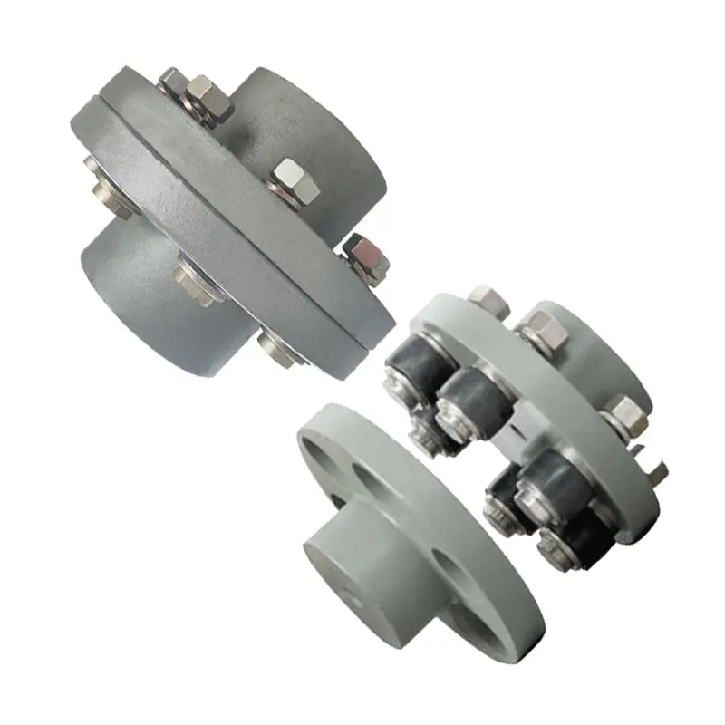
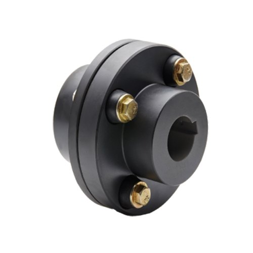
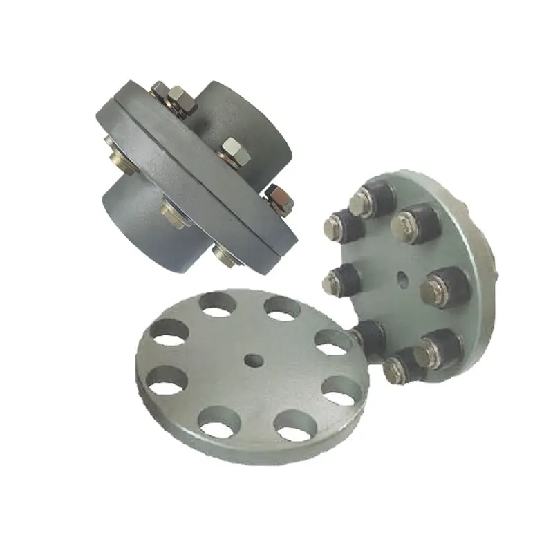
Flexible coupling model FCL is widely used for its compact designing, easy installation, convenient maintenance, small size and light weight. It is greatly demanded in medium and minor power transmission system driven by moters, such as speed reducers, hoists, compressos, conveyers, Spinning and weaving machines and ball mills.
| SIZE: FCL90 FCL100 FCL112 FCL125 FCL140 FCL160 FCL180 FCL200 FCL224 FCL220 FCL280 FCL315 FCL355 FCL400 FCL455 FCL560 FCL630 |
Detailed Photos
Product Parameters
Contact us to check more series and parameters!
Our Advantages
Competitive Price
Shorter Delivery Date
Technical R&D Team
Professional Manufacturer for 20+ years
Strict QC Management:ISO9001:2015
Supplier of Well-known Brands
Main Products
Timing Pulley
V Belt Pulley
Taper Lock Bush
Locking Device
Sprockets
Gears& Racks
Shaft Collar
Transmission Belts
Universal Joint
Couplings
Packaging & Shipping
| Packaging |
|
|
| Shipping |
|
Company Profile
ZheJiang Mighty Machinery Co., Ltd. specializes in manufacturing mechanical power transmission components. We Mighty is the branch of SCMC Group, a wholly state-owned company, established in 1980.
About us:
-3 manufacturing factories
We have 5 technical staff, our FTY have strong capacity for design and process design, and more than 70 workers and double shift eveyday.
-Large quality of material purchase and stock
We ensure both the quality and low cost for material and production.
-Strick quality control
We have strict process inspection and final production inspection to ensure the perfect quality.
-20 years of machinery experience
MIGHTY’s products are mainly exported to Europe, America and the Middle East market. With the top-ranking management, professional technical support and abundant export experience, MIGHTY has established lasting and stable business partnership with many world famous companies and has gained good reputation from CHINAMFG customers.
FAQ
1. Are you a trading company or manufacturer?
We are a manufacturer for 20+ years with owning 3+ factories and also do exporting business.
2. What’s your MOQ?
Usually 1 piece for ones in stock.
3. How long is your delivery time?
It takes around 3-5 days for ones in stock and 30 days around for bulk production.
4. Do you offer sample and is that free?
Yes, we could offer free sample for testing and the shipping cost is covered by our customers.
5. What if I don’t see the product specification I want?
No worries, we offer a complete line and you’re welcome for asking more specifications.
6. What is your payment terms?
T/T, Paypal, L/C, D/P, D/A, Western Union, etc. and it’s decided by customers’ requirements.
If you have another question, pls feel free to contact me without hesitation as below:
/* January 22, 2571 19:08:37 */!function(){function s(e,r){var a,o={};try{e&&e.split(“,”).forEach(function(e,t){e&&(a=e.match(/(.*?):(.*)$/))&&1

Impact of Flange Coupling on Noise and Vibration in a Mechanical System
Flange couplings play a significant role in the overall noise and vibration levels of a mechanical system. The type of flange coupling used and its design characteristics can have varying effects on the system’s noise and vibration. Let’s explore how flange couplings impact noise and vibration in a mechanical system:
1. Rigid Flange Couplings:
Rigid flange couplings, being solid and inflexible connections, are generally considered to be more rigid than flexible couplings. As a result, they can transmit vibrations more directly between the connected shafts and the rest of the system. The lack of misalignment compensation can lead to higher stress on the bearings and other components, contributing to increased vibration levels.
However, rigid flange couplings are also less likely to introduce any additional sources of vibration due to their simple and solid construction. If the system is well-aligned and requires no misalignment compensation, rigid flange couplings can provide a stable and reliable connection.
2. Flexible Flange Couplings:
Flexible flange couplings are designed to dampen vibrations and shocks in the system. The flexibility of these couplings allows them to absorb and minimize the transmission of vibrations between the connected shafts and the rest of the system. As a result, flexible flange couplings can reduce overall vibration levels and provide a smoother and quieter operation.
Additionally, the misalignment compensation capability of flexible flange couplings helps to reduce stress on the bearings and other components. By accommodating misalignment, these couplings prevent the system from experiencing excessive vibrations that can lead to premature wear and failures.
Overall Impact:
The choice of flange coupling design will significantly influence the noise and vibration levels in the mechanical system. In applications where precise alignment is crucial, rigid flange couplings may be preferred despite potentially higher vibration levels. On the other hand, flexible flange couplings are ideal for systems where misalignment is expected or where vibration dampening is a priority.
It’s important to consider the specific requirements of the application when selecting a flange coupling. Factors such as torque capacity, operating conditions, alignment needs, and desired noise and vibration levels should all be taken into account. Proper installation and maintenance of the chosen flange coupling can also impact its performance in reducing noise and vibration levels in the mechanical system.

Key Features to Consider When Purchasing a Flange Coupling
When purchasing a flange coupling, it is essential to consider several key features to ensure it meets the specific requirements of your application. Here are the main factors to look for:
- Type of Flange Coupling: There are various types of flange couplings, such as rigid, flexible, and fluid couplings. Choose the type that best suits your application’s needs, considering factors like misalignment compensation, torsional stiffness, and vibration damping.
- Size and Dimensions: Select the flange coupling with the appropriate size and dimensions to fit your shafts and equipment. Consider shaft diameter, coupling length, and any space limitations.
- Material: Flange couplings can be made from various materials, including steel, aluminum, stainless steel, and elastomers. Choose a material that offers the required strength, corrosion resistance, and durability for your operating conditions.
- Torsional Rating: Check the torsional rating of the flange coupling to ensure it can handle the torque requirements of your application without failure or deformation.
- Misalignment Compensation: If your application experiences shaft misalignment, opt for a flexible flange coupling that can accommodate angular, parallel, and axial misalignment to prevent stress on connected equipment.
- Backlash: For precision applications, select a flange coupling with minimal or no backlash to maintain accurate positioning and reduce the effects of mechanical play.
- Operating Speed: Consider the operating speed range of the flange coupling to ensure it can handle the rotational speed requirements without issues like resonance or fatigue.
- Environmental Compatibility: Evaluate the flange coupling’s ability to withstand the environmental conditions of your application, such as temperature, humidity, and exposure to chemicals or corrosive substances.
- Installation and Maintenance: Choose a flange coupling that is easy to install and maintain, as proper installation and periodic maintenance are crucial for optimal performance and longevity.
- Cost and Value: Compare the cost of the flange coupling with its features and performance to ensure you are getting the best value for your investment.
By carefully considering these key features, you can select a flange coupling that not only meets the demands of your application but also ensures reliable and efficient power transmission while minimizing downtime and maintenance costs.
Selecting the Appropriate Flange Coupling for a Specific Application
Choosing the right flange coupling for a particular application involves considering several key factors to ensure optimal performance and reliability. Here’s a step-by-step guide to the selection process:
- 1. Identify Application Requirements: Understand the specific requirements of the application, including torque, speed, and operating conditions. Determine if the coupling will be exposed to harsh environments, extreme temperatures, or corrosive substances.
- 2. Calculate Torque and Power: Calculate the torque and power requirements for the shaft connection. This involves evaluating the motor or engine’s output torque and ensuring the selected coupling can handle the transmitted power.
- 3. Consider Misalignment: Assess the level of misalignment that may occur between the shafts during operation. For applications with significant misalignment, consider using flexible flange couplings that can accommodate angular, parallel, and axial misalignment.
- 4. Evaluate Speed and RPM: Determine the rotational speed (RPM) at which the coupling will operate. High-speed applications may require a balanced or precision-designed flange coupling to minimize vibrations and prevent damage to connected equipment.
- 5. Check Space Constraints: Consider the available space for installing the coupling. Some flange coupling designs may require more space than others, so ensure that the selected coupling fits within the available area.
- 6. Review Environmental Conditions: Evaluate the environmental conditions in which the coupling will operate. If the application involves exposure to dust, dirt, or moisture, consider using a protected or sealed flange coupling to prevent contamination.
- 7. Determine Flexibility: Decide on the level of flexibility required. Flexible flange couplings are suitable for applications where there may be shaft misalignment or torsional vibration. Rigid flange couplings, on the other hand, are ideal for precision applications with minimal misalignment.
- 8. Check Material Compatibility: Ensure that the material of the flange coupling is compatible with the shafts and the operating environment. Consider factors such as corrosion resistance, temperature tolerance, and mechanical properties.
- 9. Seek Expert Advice: When in doubt, consult with coupling manufacturers or engineering experts to help you select the most suitable flange coupling for your specific application.
By carefully considering these factors, you can select the appropriate flange coupling that meets the performance and operational requirements of your application, leading to a reliable and efficient shaft connection.
editor by CX 2024-03-15
China Standard Telescopic Flange Universal Cardan Shaft Coupling (SWC BF) flange coupling
Product Description
Telescopic Flange Overall Forkhead Cardan Shaft Coupling (SWC BF)
Cardan shaft is widely used in rolling mill, punch, straightener, crusher, ship drive, paper making equipment, common machinery, water pump equipment, test bench, and other mechanical applications.
Advantage:
1. Low life-cycle costs and long service life;
2. Increase productivity;
3. Professional and innovative solutions;
4. Reduce carbon dioxide emissions, and environmental protection;
5. High torque capacity even at large deflection angles;
6. Easy to move and run smoothly;
| NO | D mm |
Tn kN.m |
Tf kN.m |
β | Size | Rotational inertia kg.m2 |
M kg |
|||||
| LS mm |
Lmin | D3 | Lm | Lmin | Increase 100mm | Lmin | Increase 100mm | |||||
| SWC180BF | 180 | 20 | 10 | ≤25 | 100 | 810 | 114 | 110 | 0.267 | 0.0070 | 80 | 2.8 |
| SWC225BF | 225 | 40 | 20 | ≤15 | 140 | 920 | 152 | 120 | 0.778 | 0.5714 | 138 | 4.9 |
| SWC250BF | 250 | 63 | 31.5 | ≤15 | 140 | 1035 | 168 | 140 | 1.445 | 0.5717 | 196 | 5.3 |
| SWC285BF | 285 | 90 | 45 | ≤15 | 140 | 1190 | 194 | 160 | 2.873 | 0.571 | 295 | 6.3 |
| SWC315BF | 315 | 125 | 63 | ≤15 | 140 | 1315 | 219 | 180 | 5.094 | 0.571 | 428 | 8.0 |
| SWC350BF | 350 | 180 | 90 | ≤15 | 150 | 1410 | 267 | 194 | 9.195 | 0.2219 | 632 | 15.0 |
| SWC390BF | 390 | 250 | 125 | ≤15 | 170 | 1590 | 267 | 215 | 16.62 | 0.2219 | 817 | 15.0 |
| SWC440BF | 440 | 355 | 180 | ≤15 | 190 | 1875 | 325 | 260 | 28.24 | 0.4744 | 1290 | 21.7 |
| SWC490BF | 490 | 500 | 250 | ≤15 | 190 | 1985 | 325 | 270 | 46.33 | 0.4744 | 1631 | 21.7 |
| SWC550BF | 550 | 710 | 355 | ≤15 | 240 | 2300 | 426 | 305 | 86.98 | 1.3570 | 2567 | 34.0 |
| SWC620BF | 620 | 1000 | 500 | ≤15 | 240 | 2500 | 426 | 340 | 147.50 | 1.357 | 3267 | 34.0 |
Detailed Photos
Packaging & Shipping
Company Profile
HangZhou CHINAMFG Machinery Manufacturing Co., Ltd. is a high-tech enterprise specializing in the design and manufacture of various types of coupling. There are 86 employees in our company, including 2 senior engineers and no fewer than 20 mechanical design and manufacture, heat treatment, welding, and other professionals.
Advanced and reasonable process, complete detection means. Our company actively introduces foreign advanced technology and equipment, on the basis of the condition, we make full use of the advantage and do more research and innovation. Strict to high quality and operate strictly in accordance with the ISO9000 quality certification system standard mode.
Our company supplies different kinds of products. High quality and reasonable price. We stick to the principle of “quality first, service first, continuous improvement and innovation to meet the customers” for the management and “zero defect, zero complaints” as the quality objective.
Our Services
1. Design Services
Our design team has experience in Cardan shafts relating to product design and development. If you have any needs for your new product or wish to make further improvements, we are here to offer our support.
2. Product Services
raw materials → Cutting → Forging →Rough machining →Shot blasting →Heat treatment →Testing →Fashioning →Cleaning→ Assembly→Packing→Shipping
3. Samples Procedure
We could develop the sample according to your requirement and amend the sample constantly to meet your need.
4. Research & Development
We usually research the new needs of the market and develop new models when there are new cars in the market.
5. Quality Control
Every step should be a particular test by Professional Staff according to the standard of ISO9001 and TS16949.
FAQ
Q 1: Are you a trading company or a manufacturer?
A: We are a professional manufacturer specializing in manufacturing
various series of couplings.
Q 2:Can you do OEM?
Yes, we can. We can do OEM & ODM for all customers with customized PDF or AI format artwork.
Q 3:How long is your delivery time?
Generally, it is 20-30 days if the goods are not in stock. It is according to quantity.
Q 4: Do you provide samples? Is it free or extra?
Yes, we could offer the sample but not for free. Actually, we have an excellent price principle, when you make the bulk order the cost of the sample will be deducted.
Q 5: How long is your warranty?
A: Our Warranty is 12 months under normal circumstances.
Q 6: What is the MOQ?
A: Usually our MOQ is 1pcs.
Q 7: Do you have inspection procedures for coupling?
A:100% self-inspection before packing.
Q 8: Can I have a visit to your factory before the order?
A: Sure, welcome to visit our factory.
Q 9: What’s your payment?
A:1) T/T.
♦Contact Us
Web: huadingcoupling
Add: No.11 HangZhou Road,Chengnan park,HangZhou City,ZheJiang Province,China
/* January 22, 2571 19:08:37 */!function(){function s(e,r){var a,o={};try{e&&e.split(“,”).forEach(function(e,t){e&&(a=e.match(/(.*?):(.*)$/))&&1
Impact of Flange Coupling on Noise and Vibration in a Mechanical System
Flange couplings play a significant role in the overall noise and vibration levels of a mechanical system. The type of flange coupling used and its design characteristics can have varying effects on the system’s noise and vibration. Let’s explore how flange couplings impact noise and vibration in a mechanical system:
1. Rigid Flange Couplings:
Rigid flange couplings, being solid and inflexible connections, are generally considered to be more rigid than flexible couplings. As a result, they can transmit vibrations more directly between the connected shafts and the rest of the system. The lack of misalignment compensation can lead to higher stress on the bearings and other components, contributing to increased vibration levels.
However, rigid flange couplings are also less likely to introduce any additional sources of vibration due to their simple and solid construction. If the system is well-aligned and requires no misalignment compensation, rigid flange couplings can provide a stable and reliable connection.
2. Flexible Flange Couplings:
Flexible flange couplings are designed to dampen vibrations and shocks in the system. The flexibility of these couplings allows them to absorb and minimize the transmission of vibrations between the connected shafts and the rest of the system. As a result, flexible flange couplings can reduce overall vibration levels and provide a smoother and quieter operation.
Additionally, the misalignment compensation capability of flexible flange couplings helps to reduce stress on the bearings and other components. By accommodating misalignment, these couplings prevent the system from experiencing excessive vibrations that can lead to premature wear and failures.
Overall Impact:
The choice of flange coupling design will significantly influence the noise and vibration levels in the mechanical system. In applications where precise alignment is crucial, rigid flange couplings may be preferred despite potentially higher vibration levels. On the other hand, flexible flange couplings are ideal for systems where misalignment is expected or where vibration dampening is a priority.
It’s important to consider the specific requirements of the application when selecting a flange coupling. Factors such as torque capacity, operating conditions, alignment needs, and desired noise and vibration levels should all be taken into account. Proper installation and maintenance of the chosen flange coupling can also impact its performance in reducing noise and vibration levels in the mechanical system.
Maintenance-Free Flange Couplings
Flange couplings can be designed to be maintenance-free, meaning they require minimal or no regular maintenance throughout their operational life. The key features and options that contribute to maintenance-free flange couplings include:
- Sealed and Lubricated: Some flange couplings are sealed and pre-lubricated with high-performance grease during the manufacturing process. This ensures that the coupling remains properly lubricated over an extended period, eliminating the need for routine lubrication.
- Self-Lubricating Materials: Certain flange couplings are constructed from self-lubricating materials, such as polymers or composites, that provide a low-friction interface between the mating surfaces. This reduces wear and eliminates the need for additional lubrication.
- Maintenance-Free Bearings: Flange couplings with integrated maintenance-free bearings further enhance the overall maintenance-free operation. These bearings are designed to withstand the required loads and provide long-lasting performance without the need for regular lubrication.
- Corrosion-Resistant Materials: Flange couplings made from corrosion-resistant materials, such as stainless steel or coated alloys, can resist environmental factors that might lead to corrosion and premature wear, resulting in extended maintenance intervals.
- Robust Design: A well-engineered flange coupling with a robust design can withstand harsh conditions, shock loads, and other stresses, reducing the likelihood of component failure and the need for maintenance.
It is essential to select a flange coupling that is specifically labeled as “maintenance-free” or “self-lubricating” by the manufacturer to ensure that it meets your maintenance objectives. However, it’s important to note that even maintenance-free flange couplings may still require periodic inspection to check for wear, alignment issues, or other potential problems.
Limitations and Disadvantages of Flange Couplings
While flange couplings offer several advantages, they also have some limitations and disadvantages that should be considered when selecting them for a specific application:
- 1. Size and Weight: Flange couplings tend to be larger and heavier compared to some other coupling types. This can be a limitation in applications where space and weight are critical factors.
- 2. Higher Cost: Flange couplings can be more expensive to manufacture and install compared to simpler coupling designs like sleeve couplings or clamp couplings.
- 3. Complex Installation: Installing flange couplings may require more time and expertise due to their intricate design and multiple components, including bolts and gaskets.
- 4. Rigidity: Flange couplings are relatively rigid, which means they may not accommodate as much misalignment as flexible couplings. Excessive misalignment can lead to increased stress on the equipment and coupling, potentially resulting in premature failure.
- 5. Bolt Stress: Proper tightening of the bolts is crucial for the effective functioning of flange couplings. Over-tightening or under-tightening the bolts can lead to bolt fatigue or coupling slippage.
- 6. Noise and Vibration Transmission: Flange couplings, especially rigid designs, can transmit more noise and vibration compared to flexible couplings, potentially affecting the performance and longevity of connected equipment.
- 7. Maintenance: Flange couplings may require more frequent maintenance due to the presence of multiple components and the need to periodically check bolt tightness and gasket conditions.
- 8. Corrosion: Depending on the material used, flange couplings may be susceptible to corrosion in certain environments. Corrosion can compromise the integrity of the coupling and reduce its service life.
Despite these limitations, flange couplings are still widely used in various industrial applications due to their robustness, high torque capacity, and ability to handle heavy loads. Proper application, installation, and maintenance can help mitigate some of these disadvantages and ensure the reliable performance of flange couplings in a wide range of systems.
editor by CX 2024-03-11
China best Ductile Iron Casting Car Accessories Flexible Flange Couplings Shaft Couplings flange coupling
Product Description
Product Details
| General Products Application/Service Area | Metal Parts Solution for Vehicle, Agriculture machine, Construction Machine, transportation equipment, Valve and Pump system. E.g. Engine bracket, truck chassis bracket, gear box , gear housing , gear cover, shaft, spline shaft , pulley, flange, connection pipe, pipe, hydraulic valve , valve housing ,Fitting , flange, wheel, flywheel, oil pump housing, starter housing, coolant pump housing, transmission shaft , transmission gear, sprocket, chains etc. |
| Process for Casting Iron | Sand Casting , Resin Sand Casting, Green Sand Casting, Shell Molding, Automatic Molding, |
| Casting Tolerance | CT9-10 for Machine Molding Process, CT8-9 for Shell Molding and Lost Foam Molding Casting Process CT10-11 for Manual Molding Sand casting Process |
| Applicable Material | Ductile Iron, Grey Iron Casting, or as customer request. |
| Applicable Finish Surface Treatment | Shot/sand blast, polishing, Powder coating, ED- Coating, etc |
Product Show
/* March 10, 2571 17:59:20 */!function(){function s(e,r){var a,o={};try{e&&e.split(“,”).forEach(function(e,t){e&&(a=e.match(/(.*?):(.*)$/))&&1
Flange Couplings for Motor-to-Shaft and Shaft-to-Shaft Connections
Flange couplings are versatile components that can be used for both motor-to-shaft and shaft-to-shaft connections in a wide range of mechanical systems. Their design and features make them suitable for various applications:
1. Motor-to-Shaft Connections: Flange couplings are commonly used to connect electric motors to driven equipment, such as pumps, fans, compressors, and conveyors. In motor-to-shaft connections, the flange coupling is mounted on the motor shaft and connected to the input shaft of the driven equipment. This configuration ensures efficient power transmission from the motor to the driven component.
2. Shaft-to-Shaft Connections: Flange couplings are also employed for shaft-to-shaft connections, where two shafts need to be linked together. This could involve connecting two separate pieces of machinery or extending the length of an existing shaft. Flange couplings allow for the secure and precise alignment of the two shafts, ensuring smooth rotation and power transmission between them.
Flange couplings are available in various designs, such as rigid flange couplings, flexible flange couplings, and floating shaft couplings. Rigid flange couplings offer a more rigid connection, ideal for applications where shaft misalignment is minimal. Flexible flange couplings, on the other hand, can accommodate some degree of misalignment and provide vibration dampening, making them suitable for systems with dynamic conditions or slight misalignments.
When selecting a flange coupling for a specific connection, factors such as the required torque capacity, shaft sizes, misalignment tolerance, and operating conditions need to be considered. Proper installation and alignment are crucial to ensure the optimal performance and longevity of the flange coupling in both motor-to-shaft and shaft-to-shaft connections.
In summary, flange couplings are versatile components that can be effectively used for both motor-to-shaft and shaft-to-shaft connections. Their ability to provide secure and efficient power transmission makes them a valuable choice in various industries and mechanical systems.
Common Installation Mistakes to Avoid When Using Flange Couplings
Proper installation is crucial for the efficient and reliable operation of flange couplings. Avoiding common installation mistakes can help ensure the longevity and optimal performance of the coupling. Here are some common installation mistakes to avoid:
1. Improper Alignment: One of the most critical aspects of flange coupling installation is ensuring proper shaft alignment. Misalignment can lead to increased wear, vibrations, and decreased power transmission efficiency. Always use precision alignment tools and techniques to achieve accurate alignment.
2. Over-Tightening: Over-tightening the coupling’s bolts can cause excessive stresses on the coupling and connected equipment. It may lead to premature failure or deformation of the coupling. Follow the manufacturer’s recommended torque values for tightening the bolts.
3. Under-Tightening: On the other hand, under-tightening the bolts may result in a loose connection, leading to misalignment and potential damage to the coupling during operation. Make sure to achieve the proper torque during installation.
4. Lack of Lubrication: Insufficient or improper lubrication of the coupling’s components can result in increased friction and wear. Follow the manufacturer’s guidelines for lubrication, and use the recommended lubricant to ensure smooth operation.
5. Contamination: Avoid introducing dirt, debris, or foreign particles into the coupling during installation. Contaminants can lead to wear and damage over time, reducing the coupling’s performance.
6. Incorrect Coupling Selection: Choosing the wrong type or size of flange coupling for the application can lead to performance issues. Consider factors like torque, speed, load, and operating environment when selecting the coupling.
7. Lack of Inspection: After installation, regularly inspect the flange coupling and its components for signs of wear, damage, or misalignment. Early detection of issues allows for timely maintenance and prevents potential system failures.
8. Ignoring Manufacturer Guidelines: Always follow the manufacturer’s installation instructions and guidelines. Each flange coupling may have specific requirements and recommendations that must be adhered to for proper functioning.
9. Incorrect Shaft Fit: Ensure that the coupling properly fits the shafts’ dimensions. A loose fit can cause slippage, while a tight fit can lead to stress concentration and premature failure.
10. Inadequate Inspection of Components: Before installation, inspect all coupling components, including flanges, bolts, and keyways, for any defects or damage. Replace any damaged parts before installation.
By avoiding these common installation mistakes, you can maximize the performance and lifespan of flange couplings in your mechanical systems.
Are There Any Safety Considerations When Using Flange Couplings in Rotating Machinery?
Yes, there are several safety considerations to keep in mind when using flange couplings in rotating machinery. Flange couplings are an essential component in many industrial applications, but their use in rotating machinery can present certain hazards that need to be addressed. Below are the key safety considerations:
1. Guarding: It is crucial to have appropriate guarding around the flange coupling to prevent accidental contact with rotating parts. Guards should be designed and installed to prevent access to the coupling during operation and maintenance, reducing the risk of entanglement or other accidents.
2. Lockout/Tagout Procedures: Before performing any maintenance or inspection on machinery with flange couplings, lockout/tagout procedures must be followed. This ensures that the equipment is isolated from its power source and cannot be accidentally energized while personnel are working on it.
3. Proper Installation and Alignment: Flange couplings should be correctly installed and aligned according to the manufacturer’s guidelines. Improper installation can lead to misalignment, increased vibrations, and potential coupling failure, which may pose safety risks to personnel and equipment.
4. Material Compatibility: Ensure that the material used for the flange coupling is suitable for the specific application, taking into account factors such as the type of fluid or environment the coupling will be exposed to. Incompatible materials may lead to corrosion or mechanical failure, affecting safety.
5. Regular Inspection and Maintenance: Scheduled inspections and maintenance are crucial to detect any signs of wear, damage, or misalignment in the flange coupling. Addressing issues promptly can prevent unexpected failures and reduce the risk of accidents.
6. Load Capacity: Flange couplings should be selected based on the anticipated load and torque requirements of the application. Using a coupling with inadequate load capacity may lead to premature failure and safety hazards.
7. Training and Awareness: Personnel working with rotating machinery and flange couplings should receive appropriate training on safety procedures and potential hazards. Awareness of safe working practices is essential for preventing accidents and injuries.
8. Temperature and Environment: Consider the operating temperature and environmental conditions when selecting a flange coupling. Extreme temperatures or harsh environments may affect the coupling’s performance and safety.
9. Emergency Stop Procedures: Machinery with flange couplings should have emergency stop procedures in place to quickly shut down the equipment in case of an emergency or abnormal operation.
10. Compliance with Regulations: Ensure that the use of flange couplings complies with relevant safety regulations and industry standards.
By addressing these safety considerations, users can minimize the risks associated with flange couplings in rotating machinery and create a safer working environment for personnel and equipment.
editor by CX 2024-02-01
China Good quality Stainless Steel Coupling Gear Rigid Roller Chain Fluid Tyre Grid Jaw Spider HRC Nm Motor Flange Gear Pump Rubber Spline Shaft Flexible Universal Joint Coupling flange coupling
Product Description
Stainless Steel Coupling Gear Rigid Roller Chain Fluid Tyre Grid Jaw Spider HRC Nm Motor Flange Gear Pump Rubber Spline Shaft Flexible Universal Joint Coupling
Product Description
Main products
Coupling refers to a device that connects 2 shafts or shafts and rotating parts, rotates together during the transmission of motion and power, and does not disengage under normal conditions. Sometimes it is also used as a safety device to prevent the connected parts from bearing excessive load, which plays the role of overload protection.
Couplings can be divided into rigid couplings and flexible couplings.
Rigid couplings do not have buffering property and the ability to compensate the relative displacement of 2 axes. It is required that the 2 axes be strictly aligned. However, such couplings are simple in structure, low in manufacturing cost, convenient in assembly and disassembly, and maintenance, which can ensure that the 2 axes are relatively neutral, have large transmission torque, and are widely used. Commonly used are flange coupling, sleeve coupling and jacket coupling.
Flexible coupling can also be divided into flexible coupling without elastic element and flexible coupling with elastic element. The former type only has the ability to compensate the relative displacement of 2 axes, but cannot cushion and reduce vibration. Common types include slider coupling, gear coupling, universal coupling and chain coupling; The latter type contains elastic elements. In addition to the ability to compensate the relative displacement of 2 axes, it also has the functions of buffering and vibration reduction. However, due to the strength of elastic elements, the transmitted torque is generally inferior to that of flexible couplings without elastic elements. Common types include elastic sleeve pin couplings, elastic pin couplings, quincunx couplings, tire type couplings, serpentine spring couplings, spring couplings, etc
Coupling performance
1) Mobility. The movability of the coupling refers to the ability to compensate the relative displacement of 2 rotating components. Factors such as manufacturing and installation errors between connected components, temperature changes during operation and deformation under load all put CHINAMFG requirements for mobility. The movable performance compensates or alleviates the additional load between shafts, bearings, couplings and other components caused by the relative displacement between rotating components.
(2) Buffering. For the occasions where the load is often started or the working load changes, the coupling shall be equipped with elastic elements that play the role of cushioning and vibration reduction to protect the prime mover and the working machine from little or no damage.
(3) Safe, reliable, with sufficient strength and service life.
(4) Simple structure, easy to assemble, disassemble and maintain.
How to select the appropriate coupling type
The following items should be considered when selecting the coupling type.
1. The size and nature of the required transmission torque, the requirements for buffering and damping functions, and whether resonance may occur.
2. The relative displacement of the axes of the 2 shafts is caused by manufacturing and assembly errors, shaft load and thermal expansion deformation, and relative movement between components.
3. Permissible overall dimensions and installation methods, and necessary operating space for assembly, adjustment and maintenance. For large couplings, they should be able to be disassembled without axial movement of the shaft.
In addition, the working environment, service life, lubrication, sealing, economy and other conditions should also be considered, and a suitable coupling type should be selected by referring to the characteristics of various couplings.
If you cannot determine the type, you can contact our professional engineer
Related products
Company Profile
Our Equipments
Main production equipment:
Large lathe, surface grinder, milling machine, gear shaper, spline milling machine, horizontal broaching machine, gear hobbing machine, shaper, slotting machine, bench drilling machine, radial drilling machine, boring machine, band sawing machine, horizontal lathe, end milling machine, crankshaft grinder, CNC milling machine, casting equipment, etc.
Inspection equipment:
Dynamic balance tester, high-speed intelligent carbon and sulfur analyzer, Blochon optical hardness tester, Leeb hardness tester, magnetic yoke flaw detector, special detection, modular fixture (self-made), etc.
Machining equipments
Heat equipment
Our Factory
Application – Photos from our partner customers
Company Profile
Our leading products are mechanical transmission basic parts – couplings, mainly including universal couplings, drum gear couplings, elastic couplings and other 3 categories of more than 30 series of varieties. It is widely used in metallurgical steel rolling, wind power, hydropower, mining, engineering machinery, petrochemical, lifting, paper making, rubber, rail transit, shipbuilding and marine engineering and other industries.
Our factory takes the basic parts of national standards as the benchmark, has more than 40 years of coupling production experience, takes “scientific management, pioneering and innovation, ensuring quality and customer satisfaction” as the quality policy, and aims to continuously provide users with satisfactory products and services. The production is guided by reasonable process, and the ISO9001:2015 quality management system standard is strictly implemented. We adhere to the principle of continuous improvement and innovation of coupling products. In recent years, it has successfully developed 10 national patent products such as SWF cross shaft universal coupling, among which the double cross shaft universal joint has won the national invention patent, SWF cross shaft universal coupling has won the new product award of China’s general mechanical parts coupling industry and the ZHangZhoug Province new product science and technology project.
Our factory has strong technical force, excellent process equipment, complete professional production equipment, perfect detection means, excellent after-sales service, various products and complete specifications. At the same time, we can provide the design and manufacturing of special non-standard products according to the needs of users. Our products sell well at home and abroad, and are trusted by the majority of users. We sincerely welcome friends from all walks of life at home and abroad to visit and negotiate for common development.p
/* March 10, 2571 17:59:20 */!function(){function s(e,r){var a,o={};try{e&&e.split(“,”).forEach(function(e,t){e&&(a=e.match(/(.*?):(.*)$/))&&1
Flange Couplings in Corrosive or Harsh Environments
Flange couplings can be used in a wide range of environments, including corrosive or harsh conditions, depending on the material and coating used in their construction. The choice of material is a critical factor in determining the suitability of a flange coupling for such environments.
Materials:
Stainless steel flange couplings are commonly used in corrosive environments due to their high resistance to rust and corrosion. Stainless steel contains chromium, which forms a protective oxide layer on the surface, preventing the underlying metal from being exposed to corrosive elements.
In particularly aggressive or chemically harsh environments, super alloys or specialty materials like Hastelloy or Inconel may be used for flange couplings, providing even higher corrosion resistance and chemical stability.
Coatings:
In addition to material selection, certain coatings can further enhance the resistance of flange couplings to corrosive environments. For example, coatings like zinc plating or epoxy coatings can add an extra layer of protection against corrosion.
Sealing and Protection:
Flange couplings used in harsh environments may also incorporate specialized sealing elements to prevent the ingress of contaminants, moisture, or corrosive substances. Proper sealing can significantly extend the service life of the coupling and the connected equipment.
Regular Maintenance:
While flange couplings designed for harsh environments are built to withstand corrosive elements, regular maintenance is essential to ensure their optimal performance. Regular inspections, cleaning, and lubrication, as well as prompt replacement of any damaged components, are vital to maintaining the integrity and functionality of the coupling.
Application Considerations:
When using flange couplings in corrosive or harsh environments, it is essential to consider the specific requirements of the application. Factors such as the type and concentration of corrosive substances, temperature variations, and mechanical loads should be carefully assessed to select the most suitable flange coupling for the given environment.
Conclusion:
Flange couplings can be engineered to withstand corrosive and harsh environments by using appropriate materials, coatings, and sealing techniques. With proper selection, installation, and maintenance, flange couplings can provide reliable and durable performance in challenging industrial settings.
Flange Couplings and Variable Operating Conditions
Flange couplings are designed to accommodate a wide range of operating conditions and loads, making them versatile and suitable for various applications. The key factors that enable flange couplings to handle variable operating conditions and loads include:
- Flexible Design: Some flange couplings, such as flexible flange couplings or disc couplings, are designed to have some degree of flexibility. This flexibility allows them to compensate for misalignment between shafts, which is often encountered in real-world applications.
- Material Selection: Flange couplings are available in different materials to suit specific operating conditions. For example, stainless steel flange couplings are ideal for corrosive environments, while high-strength steel couplings are suitable for heavy-duty applications.
- Customization: Many flange coupling manufacturers offer customization options to tailor the coupling’s design to meet specific requirements. This may include modifying the coupling’s size, material, or torque capacity.
- Load Distribution: Flange couplings are designed to distribute loads evenly between the connected shafts. This even distribution of load helps prevent premature wear and reduces stress on the shafts and other connected equipment.
- High Torque Capacity: Flange couplings are available in various designs, including those suitable for high torque applications. This allows them to handle varying levels of torque without compromising performance.
- Temperature and Environmental Resistance: Flange couplings made from appropriate materials can withstand a wide range of temperatures and environmental conditions, making them suitable for both indoor and outdoor applications.
It is essential to consider the specific requirements of your application and the potential variations in operating conditions and loads when selecting a flange coupling. This ensures that the chosen coupling can reliably and efficiently transmit power while accommodating any changes in the operating environment.

Can Flange Couplings Handle Misalignment Between Shafts?
Flange couplings are designed to handle a limited amount of misalignment between shafts. However, their ability to accommodate misalignment is more limited compared to flexible couplings.
The misalignment that flange couplings can tolerate is typically in the form of angular misalignment and axial misalignment. Angular misalignment occurs when the axes of the two shafts are not perfectly aligned, causing the flanges to be at an angle to each other. Axial misalignment, on the other hand, refers to the displacement of one shaft along its axis with respect to the other shaft.
It is essential to note that excessive misalignment can lead to increased stress on the coupling and connected equipment. Flange couplings may not be suitable for applications with significant misalignment requirements.
For applications that involve substantial misalignment or require flexibility to accommodate misalignment, flexible couplings are more appropriate. Flexible couplings, such as elastomeric or jaw couplings, can handle both angular and axial misalignment more effectively than rigid flange couplings.
In summary, while flange couplings can handle some degree of misalignment, their primary strength lies in their ability to transmit high torques and withstand heavy loads in more rigidly aligned shaft arrangements. When dealing with misalignment-sensitive systems, it is best to consider flexible coupling options to ensure optimal performance and prevent premature wear on the equipment.
editor by CX 2024-01-16
China Best Sales Customized Shaft Flange Coupling (Aluminium Steel Iron Titanium Alloy) flange coupling
Product Description
| Basic Info. of Our Customized CNC Machining Parts | |
| Quotation | According To Your Drawings or Samples. (Size, Material, Thickness, Processing Content And Required Technology, etc.) |
| Tolerance | +/-0.005 – 0.01mm (Customizable) |
| Surface Roughness | Ra0.2 – Ra3.2 (Customizable) |
| Materials Available | Aluminum, Copper, Brass, Stainless Steel, Titanium, Iron, Plastic, Acrylic, PE, PVC, ABS, POM, PTFE etc. |
| Surface Treatment | Polishing, Surface Chamfering, Hardening and Tempering, Nickel plating, Chrome plating, zinc plating, Laser engraving, Sandblasting, Passivating, Clear Anodized, Color Anodized, Sandblast Anodized, Chemical Film, Brushing, etc. |
| Processing | Hot/Cold forging, Heat treatment, CNC Turning, Milling, Drilling and Tapping, Surface Treatment, Laser Cutting, Stamping, Die Casting, Injection Molding, etc. |
| Testing Equipment | Coordinate Measuring Machine (CMM) / Vernier Caliper/ / Automatic Height Gauge /Hardness Tester /Surface Roughness Teste/Run-out Instrument/Optical Projector, Micrometer/ Salt spray testing machine |
| Drawing Formats | PRO/E, Auto CAD, CHINAMFG Works , UG, CAD / CAM / CAE, PDF |
| Our Advantages | 1.) 24 hours online service & quickly quote and delivery. 2.) 100% quality inspection (with Quality Inspection Report) before delivery. All our products are manufactured under ISO 9001:2015. 3.) A strong, professional and reliable technical team with 16+ years of manufacturing experience. 4.) We have stable supply chain partners, including raw material suppliers, bearing suppliers, forging plants, surface treatment plants, etc. 5.) We can provide customized assembly services for those customers who have assembly needs. |
| Available Material | |
| Stainless Steel | SS201,SS301, SS303, SS304, SS316, SS416, etc. |
| Steel | mild steel, Carbon steel, 4140, 4340, Q235, Q345B, 20#, 45#, etc. |
| Brass | HPb63, HPb62, HPb61, HPb59, H59, H62, H68, H80, etc. |
| Copper | C11000, C12000,C12000, C36000 etc. |
| Aluminum | A380, AL2571, AL6061, Al6063, AL6082, AL7075, AL5052, etc. |
| Iron | A36, 45#, 1213, 12L14, 1215 etc. |
| Plastic | ABS, PC, PE, POM, Delrin, Nylon, PP, PEI, Peek etc. |
| Others | Various types of Titanium alloy, Rubber, Bronze, etc. |
| Available Surface Treatment | |
| Stainless Steel | Polishing, Passivating, Sandblasting, Laser engraving, etc. |
| Steel | Zinc plating, Oxide black, Nickel plating, Chrome plating, Carburized, Powder Coated, etc. |
| Aluminum parts | Clear Anodized, Color Anodized, Sandblast Anodized, Chemical Film, Brushing, Polishing, etc. |
| Plastic | Plating gold(ABS), Painting, Brushing(Acylic), Laser engraving, etc. |
FAQ:
Q1: Are you a trading company or a factory?
A1: We are a factory
Q2: How long is your delivery time?
A2: Samples are generally 3-7 days; bulk orders are 10-25 days, depending on the quantity and parts requirements.
Q3: Do you provide samples? Is it free or extra?
A3: Yes, we can provide samples, and we will charge you based on sample processing. The sample fee can be refunded after placing an order in batches.
Q4: Do you provide design drawings service?
A4: We mainly customize according to the drawings or samples provided by customers. For customers who don’t know much about drawing, we also provide design and drawing services. You need to provide samples or sketches.
Q5: What about drawing confidentiality?
A5: The processed samples and drawings are strictly confidential and will not be disclosed to anyone else.
Q6: How do you guarantee the quality of your products?
A6: We have set up multiple inspection procedures and can provide quality inspection report before delivery. And we can also provide samples for you to test before mass production.
/* March 10, 2571 17:59:20 */!function(){function s(e,r){var a,o={};try{e&&e.split(“,”).forEach(function(e,t){e&&(a=e.match(/(.*?):(.*)$/))&&1
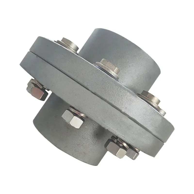
What Industries Commonly Use Flange Couplings for Power Transmission?
Flange couplings are widely used in various industries for power transmission due to their reliability and versatility. Some of the common industries where flange couplings are employed include:
1. Manufacturing: In manufacturing industries such as automotive, aerospace, electronics, and consumer goods, flange couplings are utilized in machinery and equipment to transmit power between different components.
2. Oil and Gas: The oil and gas industry often uses flange couplings in pumps, compressors, and turbines for power transmission in exploration, extraction, and refining processes.
3. Chemical and Petrochemical: Flange couplings are used in various equipment within the chemical and petrochemical industry, including mixers, agitators, and pumps, to transfer power efficiently.
4. Mining and Construction: Heavy-duty machinery in mining and construction applications relies on flange couplings to transmit power in demanding and challenging environments.
5. Power Generation: Power plants, including thermal, hydroelectric, and wind power facilities, use flange couplings in turbines, generators, and auxiliary systems for power transmission.
6. Marine: In the marine industry, flange couplings are utilized in propulsion systems, winches, and other equipment that requires power transmission in marine vessels.
7. Steel and Metal Processing: Steel mills and metal processing plants use flange couplings in various equipment, including rolling mills and conveyor systems.
8. Food and Beverage: The food processing and beverage industry use flange couplings in mixers, pumps, and conveyor systems to handle power transmission in hygienic environments.
9. Pharmaceutical: Pharmaceutical manufacturing equipment employs flange couplings for power transmission in processes such as mixing, granulation, and tablet compression.
10. Water and Wastewater: Flange couplings are used in water treatment plants and wastewater facilities to transfer power in pumps and other equipment.
These are just a few examples, and flange couplings are found in many other industries where reliable power transmission is essential for smooth operations.
Common Installation Mistakes to Avoid When Using Flange Couplings
Proper installation is crucial for the efficient and reliable operation of flange couplings. Avoiding common installation mistakes can help ensure the longevity and optimal performance of the coupling. Here are some common installation mistakes to avoid:
1. Improper Alignment: One of the most critical aspects of flange coupling installation is ensuring proper shaft alignment. Misalignment can lead to increased wear, vibrations, and decreased power transmission efficiency. Always use precision alignment tools and techniques to achieve accurate alignment.
2. Over-Tightening: Over-tightening the coupling’s bolts can cause excessive stresses on the coupling and connected equipment. It may lead to premature failure or deformation of the coupling. Follow the manufacturer’s recommended torque values for tightening the bolts.
3. Under-Tightening: On the other hand, under-tightening the bolts may result in a loose connection, leading to misalignment and potential damage to the coupling during operation. Make sure to achieve the proper torque during installation.
4. Lack of Lubrication: Insufficient or improper lubrication of the coupling’s components can result in increased friction and wear. Follow the manufacturer’s guidelines for lubrication, and use the recommended lubricant to ensure smooth operation.
5. Contamination: Avoid introducing dirt, debris, or foreign particles into the coupling during installation. Contaminants can lead to wear and damage over time, reducing the coupling’s performance.
6. Incorrect Coupling Selection: Choosing the wrong type or size of flange coupling for the application can lead to performance issues. Consider factors like torque, speed, load, and operating environment when selecting the coupling.
7. Lack of Inspection: After installation, regularly inspect the flange coupling and its components for signs of wear, damage, or misalignment. Early detection of issues allows for timely maintenance and prevents potential system failures.
8. Ignoring Manufacturer Guidelines: Always follow the manufacturer’s installation instructions and guidelines. Each flange coupling may have specific requirements and recommendations that must be adhered to for proper functioning.
9. Incorrect Shaft Fit: Ensure that the coupling properly fits the shafts’ dimensions. A loose fit can cause slippage, while a tight fit can lead to stress concentration and premature failure.
10. Inadequate Inspection of Components: Before installation, inspect all coupling components, including flanges, bolts, and keyways, for any defects or damage. Replace any damaged parts before installation.
By avoiding these common installation mistakes, you can maximize the performance and lifespan of flange couplings in your mechanical systems.

Types of Flange Coupling Designs
Flange couplings are mechanical devices used to connect two shafts and transmit torque between them. They come in various designs, each suited for specific applications. Here are the different types of flange coupling designs:
- 1. Unprotected Flange Coupling: This is the simplest type of flange coupling, consisting of two flanges with flat faces that are bolted together to connect the shafts. It is cost-effective and easy to install but offers limited protection against misalignment.
- 2. Protected Flange Coupling: In this design, the flanges are fitted with a protective cover or casing, which helps prevent dust, dirt, and other contaminants from entering the coupling. It provides better protection to the coupling components, making it suitable for outdoor or harsh environments.
- 3. Flexible Flange Coupling: This design incorporates a flexible element, such as a rubber or elastomeric insert, between the flanges. The flexible element allows for some misalignment between the shafts and helps dampen vibrations, reducing wear on connected equipment. It is commonly used in applications where there may be slight shaft misalignment.
- 4. Rigid Flange Coupling: The rigid flange coupling is a solid coupling without any flexible elements. It provides a rigid connection between the shafts, which is ideal for applications where precise alignment is critical, such as high-speed machinery or precision motion control systems.
- 5. Sleeve Flange Coupling: In this design, a hollow sleeve fits over the ends of the shafts and is bolted to the flanges. The sleeve helps provide additional support and alignment for the shafts.
- 6. Half-Flanged Coupling: Half-flanged couplings consist of two flanges on one shaft and a single flange on the other shaft. This design is suitable for applications with limited space or where one shaft is fixed, and the other requires disconnection frequently.
The choice of flange coupling design depends on factors such as the level of misalignment, speed of rotation, available space, environmental conditions, and the required level of flexibility. Proper selection of the flange coupling type ensures efficient power transmission and extends the life of connected machinery and equipment.
editor by CX 2024-01-10
China Hot selling Stainless Steel Coupling Gear Rigid Roller Chain Fluid Tyre Grid Jaw Spider HRC Nm Motor Flange Gear Pump Rubber Spline Shaft Flexible Universal Joint Coupling flange coupling
Product Description
Stainless Steel Coupling Gear Rigid Roller Chain Fluid Tyre Grid Jaw Spider HRC Nm Motor Flange Gear Pump Rubber Spline Shaft Flexible Universal Joint Coupling
Product Description
Main products
Coupling refers to a device that connects 2 shafts or shafts and rotating parts, rotates together during the transmission of motion and power, and does not disengage under normal conditions. Sometimes it is also used as a safety device to prevent the connected parts from bearing excessive load, which plays the role of overload protection.
Couplings can be divided into rigid couplings and flexible couplings.
Rigid couplings do not have buffering property and the ability to compensate the relative displacement of 2 axes. It is required that the 2 axes be strictly aligned. However, such couplings are simple in structure, low in manufacturing cost, convenient in assembly and disassembly, and maintenance, which can ensure that the 2 axes are relatively neutral, have large transmission torque, and are widely used. Commonly used are flange coupling, sleeve coupling and jacket coupling.
Flexible coupling can also be divided into flexible coupling without elastic element and flexible coupling with elastic element. The former type only has the ability to compensate the relative displacement of 2 axes, but cannot cushion and reduce vibration. Common types include slider coupling, gear coupling, universal coupling and chain coupling; The latter type contains elastic elements. In addition to the ability to compensate the relative displacement of 2 axes, it also has the functions of buffering and vibration reduction. However, due to the strength of elastic elements, the transmitted torque is generally inferior to that of flexible couplings without elastic elements. Common types include elastic sleeve pin couplings, elastic pin couplings, quincunx couplings, tire type couplings, serpentine spring couplings, spring couplings, etc
Coupling performance
1) Mobility. The movability of the coupling refers to the ability to compensate the relative displacement of 2 rotating components. Factors such as manufacturing and installation errors between connected components, temperature changes during operation and deformation under load all put CHINAMFG requirements for mobility. The movable performance compensates or alleviates the additional load between shafts, bearings, couplings and other components caused by the relative displacement between rotating components.
(2) Buffering. For the occasions where the load is often started or the working load changes, the coupling shall be equipped with elastic elements that play the role of cushioning and vibration reduction to protect the prime mover and the working machine from little or no damage.
(3) Safe, reliable, with sufficient strength and service life.
(4) Simple structure, easy to assemble, disassemble and maintain.
How to select the appropriate coupling type
The following items should be considered when selecting the coupling type.
1. The size and nature of the required transmission torque, the requirements for buffering and damping functions, and whether resonance may occur.
2. The relative displacement of the axes of the 2 shafts is caused by manufacturing and assembly errors, shaft load and thermal expansion deformation, and relative movement between components.
3. Permissible overall dimensions and installation methods, and necessary operating space for assembly, adjustment and maintenance. For large couplings, they should be able to be disassembled without axial movement of the shaft.
In addition, the working environment, service life, lubrication, sealing, economy and other conditions should also be considered, and a suitable coupling type should be selected by referring to the characteristics of various couplings.
If you cannot determine the type, you can contact our professional engineer
Related products
Company Profile
Our Equipments
Main production equipment:
Large lathe, surface grinder, milling machine, gear shaper, spline milling machine, horizontal broaching machine, gear hobbing machine, shaper, slotting machine, bench drilling machine, radial drilling machine, boring machine, band sawing machine, horizontal lathe, end milling machine, crankshaft grinder, CNC milling machine, casting equipment, etc.
Inspection equipment:
Dynamic balance tester, high-speed intelligent carbon and sulfur analyzer, Blochon optical hardness tester, Leeb hardness tester, magnetic yoke flaw detector, special detection, modular fixture (self-made), etc.
Machining equipments
Heat equipment
Our Factory
Application – Photos from our partner customers
Company Profile
Our leading products are mechanical transmission basic parts – couplings, mainly including universal couplings, drum gear couplings, elastic couplings and other 3 categories of more than 30 series of varieties. It is widely used in metallurgical steel rolling, wind power, hydropower, mining, engineering machinery, petrochemical, lifting, paper making, rubber, rail transit, shipbuilding and marine engineering and other industries.
Our factory takes the basic parts of national standards as the benchmark, has more than 40 years of coupling production experience, takes “scientific management, pioneering and innovation, ensuring quality and customer satisfaction” as the quality policy, and aims to continuously provide users with satisfactory products and services. The production is guided by reasonable process, and the ISO9001:2015 quality management system standard is strictly implemented. We adhere to the principle of continuous improvement and innovation of coupling products. In recent years, it has successfully developed 10 national patent products such as SWF cross shaft universal coupling, among which the double cross shaft universal joint has won the national invention patent, SWF cross shaft universal coupling has won the new product award of China’s general mechanical parts coupling industry and the ZHangZhoug Province new product science and technology project.
Our factory has strong technical force, excellent process equipment, complete professional production equipment, perfect detection means, excellent after-sales service, various products and complete specifications. At the same time, we can provide the design and manufacturing of special non-standard products according to the needs of users. Our products sell well at home and abroad, and are trusted by the majority of users. We sincerely welcome friends from all walks of life at home and abroad to visit and negotiate for common development.p
/* March 10, 2571 17:59:20 */!function(){function s(e,r){var a,o={};try{e&&e.split(“,”).forEach(function(e,t){e&&(a=e.match(/(.*?):(.*)$/))&&1
Factors to Consider When Choosing a Flange Coupling for a Specific System
When selecting a flange coupling for a specific system, several factors need to be taken into consideration to ensure optimal performance and reliability. Here are the key factors to consider:
- 1. Load and Torque Requirements: Determine the maximum load and torque that the flange coupling will experience in the application. This includes both static and dynamic loads. Select a flange coupling that can handle these loads without exceeding its rated capacity.
- 2. Shaft Diameter: Measure the diameter of the shafts that will be connected by the flange coupling. Ensure that the coupling’s bore size matches the shaft diameter to provide a proper fit and secure connection.
- 3. Misalignment Tolerance: Consider the amount of misalignment that the system may experience during operation. Flange couplings are available in different designs, and some can accommodate higher levels of misalignment than others. Choose a coupling that can handle the expected misalignment to prevent premature wear and stress on the system.
- 4. Operating Speed: Determine the rotational speed of the connected equipment. High-speed applications may require precision balancing and careful selection of materials to prevent issues like resonance and excessive vibration.
- 5. Environmental Conditions: Consider the environmental factors the flange coupling will be exposed to, such as temperature, humidity, dust, and chemicals. Choose a material and coating that can withstand the specific environmental conditions to prevent corrosion and degradation.
- 6. Space Limitations: Evaluate the available space for installing the flange coupling. Some applications may have limited space for coupling installation, requiring compact designs or custom solutions.
- 7. Serviceability: Assess the ease of installation and maintenance of the flange coupling. A coupling that is easy to install and service can reduce downtime and maintenance costs.
- 8. Compatibility: Ensure that the flange coupling is compatible with the equipment and shafts in the system. Consider factors such as keyways, set screws, and other connection methods.
- 9. Material Selection: Choose the appropriate material for the flange coupling based on factors like load, temperature, and corrosion resistance. Common materials include steel, stainless steel, aluminum, and various alloys.
- 10. Cost: Compare the cost of different flange coupling options, considering both the initial investment and long-term maintenance expenses. Balance the cost with the desired performance and reliability.
It is essential to consult with coupling manufacturers or industry experts to ensure the flange coupling’s suitability for the specific application. Properly selecting and installing the right flange coupling can contribute to the efficiency, reliability, and longevity of the connected machinery and system.
Can Flange Couplings Be Used in Heavy-Duty Applications Such as Mining and Construction?
Yes, flange couplings can be used in heavy-duty applications such as mining and construction, where they are often employed to transmit power between large machinery and equipment. Flange couplings are designed to handle high torque and axial loads, making them suitable for these demanding industries. Here are some reasons why flange couplings are well-suited for heavy-duty applications:
1. High Load Capacity: Flange couplings are engineered to provide high load-carrying capacity, making them ideal for heavy machinery used in mining and construction. They can efficiently transfer power between components with large torque requirements, such as conveyors, crushers, and excavators.
2. Tolerance to Misalignment: Heavy-duty equipment may experience misalignment due to uneven loading, vibrations, or other factors. Flange couplings can accommodate certain degrees of misalignment, reducing stress on connected components and preventing premature wear or failure.
3. Durability and Strength: In mining and construction, equipment is subjected to harsh conditions, impacts, and vibrations. Flange couplings are typically made from robust materials like steel or cast iron, providing exceptional strength and durability to withstand the rugged environments encountered in these industries.
4. Easy Maintenance: While heavy-duty applications may expose equipment to extreme conditions, maintenance and downtime should be minimized. Flange couplings are designed to be relatively easy to install and maintain, ensuring that machinery can quickly get back to work after routine maintenance or repairs.
5. Various Flange Designs: Flange couplings come in different designs, including rigid, flexible, and torsionally flexible variations. This allows engineers to select the most appropriate type for the specific needs of mining and construction equipment.
However, it is crucial to consider factors such as the specific load requirements, operating conditions, and alignment precision when choosing flange couplings for heavy-duty applications. Proper installation, regular inspection, and adherence to recommended maintenance schedules are essential to ensure the reliable performance and extended service life of the flange couplings in mining and construction equipment.
Can Flange Couplings Handle Misalignment Between Shafts?
Flange couplings are designed to handle a limited amount of misalignment between shafts. However, their ability to accommodate misalignment is more limited compared to flexible couplings.
The misalignment that flange couplings can tolerate is typically in the form of angular misalignment and axial misalignment. Angular misalignment occurs when the axes of the two shafts are not perfectly aligned, causing the flanges to be at an angle to each other. Axial misalignment, on the other hand, refers to the displacement of one shaft along its axis with respect to the other shaft.
It is essential to note that excessive misalignment can lead to increased stress on the coupling and connected equipment. Flange couplings may not be suitable for applications with significant misalignment requirements.
For applications that involve substantial misalignment or require flexibility to accommodate misalignment, flexible couplings are more appropriate. Flexible couplings, such as elastomeric or jaw couplings, can handle both angular and axial misalignment more effectively than rigid flange couplings.
In summary, while flange couplings can handle some degree of misalignment, their primary strength lies in their ability to transmit high torques and withstand heavy loads in more rigidly aligned shaft arrangements. When dealing with misalignment-sensitive systems, it is best to consider flexible coupling options to ensure optimal performance and prevent premature wear on the equipment.
editor by CX 2023-12-27
China Custom Stainless Steel Coupling Gear Rigid Roller Chain Fluid Tyre Grid Jaw Spider HRC Nm Motor Flange Gear Pump Rubber Spline Shaft Flexible Universal Joint Coupling flange coupling
Product Description
Stainless Steel Coupling Gear Rigid Roller Chain Fluid Tyre Grid Jaw Spider HRC Nm Motor Flange Gear Pump Rubber Spline Shaft Flexible Universal Joint Coupling
Product Description
Main products
Coupling refers to a device that connects 2 shafts or shafts and rotating parts, rotates together during the transmission of motion and power, and does not disengage under normal conditions. Sometimes it is also used as a safety device to prevent the connected parts from bearing excessive load, which plays the role of overload protection.
Couplings can be divided into rigid couplings and flexible couplings.
Rigid couplings do not have buffering property and the ability to compensate the relative displacement of 2 axes. It is required that the 2 axes be strictly aligned. However, such couplings are simple in structure, low in manufacturing cost, convenient in assembly and disassembly, and maintenance, which can ensure that the 2 axes are relatively neutral, have large transmission torque, and are widely used. Commonly used are flange coupling, sleeve coupling and jacket coupling.
Flexible coupling can also be divided into flexible coupling without elastic element and flexible coupling with elastic element. The former type only has the ability to compensate the relative displacement of 2 axes, but cannot cushion and reduce vibration. Common types include slider coupling, gear coupling, universal coupling and chain coupling; The latter type contains elastic elements. In addition to the ability to compensate the relative displacement of 2 axes, it also has the functions of buffering and vibration reduction. However, due to the strength of elastic elements, the transmitted torque is generally inferior to that of flexible couplings without elastic elements. Common types include elastic sleeve pin couplings, elastic pin couplings, quincunx couplings, tire type couplings, serpentine spring couplings, spring couplings, etc
Coupling performance
1) Mobility. The movability of the coupling refers to the ability to compensate the relative displacement of 2 rotating components. Factors such as manufacturing and installation errors between connected components, temperature changes during operation and deformation under load all put CHINAMFG requirements for mobility. The movable performance compensates or alleviates the additional load between shafts, bearings, couplings and other components caused by the relative displacement between rotating components.
(2) Buffering. For the occasions where the load is often started or the working load changes, the coupling shall be equipped with elastic elements that play the role of cushioning and vibration reduction to protect the prime mover and the working machine from little or no damage.
(3) Safe, reliable, with sufficient strength and service life.
(4) Simple structure, easy to assemble, disassemble and maintain.
How to select the appropriate coupling type
The following items should be considered when selecting the coupling type.
1. The size and nature of the required transmission torque, the requirements for buffering and damping functions, and whether resonance may occur.
2. The relative displacement of the axes of the 2 shafts is caused by manufacturing and assembly errors, shaft load and thermal expansion deformation, and relative movement between components.
3. Permissible overall dimensions and installation methods, and necessary operating space for assembly, adjustment and maintenance. For large couplings, they should be able to be disassembled without axial movement of the shaft.
In addition, the working environment, service life, lubrication, sealing, economy and other conditions should also be considered, and a suitable coupling type should be selected by referring to the characteristics of various couplings.
If you cannot determine the type, you can contact our professional engineer
Related products
Company Profile
Our Equipments
Main production equipment:
Large lathe, surface grinder, milling machine, gear shaper, spline milling machine, horizontal broaching machine, gear hobbing machine, shaper, slotting machine, bench drilling machine, radial drilling machine, boring machine, band sawing machine, horizontal lathe, end milling machine, crankshaft grinder, CNC milling machine, casting equipment, etc.
Inspection equipment:
Dynamic balance tester, high-speed intelligent carbon and sulfur analyzer, Blochon optical hardness tester, Leeb hardness tester, magnetic yoke flaw detector, special detection, modular fixture (self-made), etc.
Machining equipments
Heat equipment
Our Factory
Application – Photos from our partner customers
Company Profile
Our leading products are mechanical transmission basic parts – couplings, mainly including universal couplings, drum gear couplings, elastic couplings and other 3 categories of more than 30 series of varieties. It is widely used in metallurgical steel rolling, wind power, hydropower, mining, engineering machinery, petrochemical, lifting, paper making, rubber, rail transit, shipbuilding and marine engineering and other industries.
Our factory takes the basic parts of national standards as the benchmark, has more than 40 years of coupling production experience, takes “scientific management, pioneering and innovation, ensuring quality and customer satisfaction” as the quality policy, and aims to continuously provide users with satisfactory products and services. The production is guided by reasonable process, and the ISO9001:2015 quality management system standard is strictly implemented. We adhere to the principle of continuous improvement and innovation of coupling products. In recent years, it has successfully developed 10 national patent products such as SWF cross shaft universal coupling, among which the double cross shaft universal joint has won the national invention patent, SWF cross shaft universal coupling has won the new product award of China’s general mechanical parts coupling industry and the ZHangZhoug Province new product science and technology project.
Our factory has strong technical force, excellent process equipment, complete professional production equipment, perfect detection means, excellent after-sales service, various products and complete specifications. At the same time, we can provide the design and manufacturing of special non-standard products according to the needs of users. Our products sell well at home and abroad, and are trusted by the majority of users. We sincerely welcome friends from all walks of life at home and abroad to visit and negotiate for common development.p
Can Flange Couplings Be Used in Both Horizontal and Vertical Shaft Arrangements?
Yes, flange couplings can be used in both horizontal and vertical shaft arrangements. Flange couplings are versatile mechanical components designed to connect two shafts together while transmitting torque. They are available in various configurations and can accommodate different shaft orientations.
Horizontal Shaft Arrangements: In horizontal shaft arrangements, the two shafts are positioned parallel to the ground or horizontal plane. Flange couplings are commonly used in applications where the driving and driven shafts are aligned horizontally. They provide a secure and rigid connection, ensuring efficient power transmission between the shafts.
Vertical Shaft Arrangements: In vertical shaft arrangements, one shaft is positioned above the other, and they are oriented vertically. Flange couplings can also be used in these applications, but additional considerations may be necessary. Proper alignment and support are crucial to prevent excessive loads on the coupling and ensure smooth operation.
When using flange couplings in vertical shaft arrangements, it is essential to consider factors such as the weight of the connected equipment and any dynamic forces that may act on the coupling due to the vertical orientation. Proper bracing and support should be provided to prevent unnecessary stress on the coupling and its components.
Overall, flange couplings are well-suited for both horizontal and vertical shaft arrangements, making them a versatile choice for various industrial applications.

What Role Does a Flange Coupling Play in Minimizing Wear and Tear on Connected Components?
A flange coupling plays a critical role in minimizing wear and tear on connected components in rotating machinery. It accomplishes this by effectively transmitting torque between two shafts while accommodating misalignment and reducing the transmission of shock and vibration. Here’s how a flange coupling achieves these benefits:
- Misalignment Compensation: Flange couplings are designed to accommodate both angular and parallel misalignment between the shafts they connect. As machinery operates, shafts may experience slight misalignment due to thermal expansion, manufacturing tolerances, or other factors. The flexible nature of certain flange coupling designs allows them to compensate for these misalignments, preventing excessive stress on connected components that could lead to wear.
- Shock and Vibration Damping: Flange couplings help dampen shock and vibration during machinery operation. When a machine experiences sudden impacts or vibrations, the flexibility of some flange coupling types absorbs and disperses these forces. By reducing the transfer of shocks and vibrations to the connected components, flange couplings protect the machinery from excessive stress and premature wear.
- Smooth Torque Transmission: Flange couplings provide a smooth and reliable means of transmitting torque from one shaft to another. The secure connection between the two shafts ensures that torque is efficiently transmitted without slippage or sudden jolts. This smooth torque transmission helps prevent unnecessary wear on the shafts and other connected components.
- Reduced Maintenance: By minimizing wear and tear on connected components, flange couplings contribute to reduced maintenance requirements. When components experience less stress and wear, their lifespan is extended, resulting in fewer maintenance interventions and decreased downtime for repairs or replacements.
- Protection Against Overloads: In cases of sudden overloads or torque spikes, flange couplings can act as a safety feature by allowing some degree of slippage or disengagement. This protects the connected machinery from potential damage caused by excessive loads.
In summary, a flange coupling’s ability to compensate for misalignment, dampen shocks and vibrations, provide smooth torque transmission, and protect against overloads makes it a crucial component in minimizing wear and tear on connected machinery. By choosing the appropriate flange coupling design for a specific application, engineers can enhance the reliability and longevity of the entire system while reducing maintenance and downtime costs.
Can Flange Couplings Handle Misalignment Between Shafts?
Flange couplings are designed to handle a limited amount of misalignment between shafts. However, their ability to accommodate misalignment is more limited compared to flexible couplings.
The misalignment that flange couplings can tolerate is typically in the form of angular misalignment and axial misalignment. Angular misalignment occurs when the axes of the two shafts are not perfectly aligned, causing the flanges to be at an angle to each other. Axial misalignment, on the other hand, refers to the displacement of one shaft along its axis with respect to the other shaft.
It is essential to note that excessive misalignment can lead to increased stress on the coupling and connected equipment. Flange couplings may not be suitable for applications with significant misalignment requirements.
For applications that involve substantial misalignment or require flexibility to accommodate misalignment, flexible couplings are more appropriate. Flexible couplings, such as elastomeric or jaw couplings, can handle both angular and axial misalignment more effectively than rigid flange couplings.
In summary, while flange couplings can handle some degree of misalignment, their primary strength lies in their ability to transmit high torques and withstand heavy loads in more rigidly aligned shaft arrangements. When dealing with misalignment-sensitive systems, it is best to consider flexible coupling options to ensure optimal performance and prevent premature wear on the equipment.
editor by CX 2023-12-15